DATSUN B110 1969 Service Manual PDF
Manufacturer: DATSUN, Model Year: 1969, Model line: B110, Model: DATSUN B110 1969Pages: 136, PDF Size: 5.64 MB
Page 61 of 136
GooliDI
Sptem
mechamsm
IS
adopted
to
prevent
the
water
leakage
and
nOIse
completely
Note
The
water
pump
must
not
be
disassembled
since
the
bearings
are
shrmkage
fitted
to
their
bores
If
any
part
of
water
pump
is
found
defective
replace
pump
assembly
Removal
Dram
coolmg
water
completely
Take
the
fan
belt
ofT
the
pulley
Remove
fan
and
pulley
Remove
the
water
pump
Installation
InstallatIOn
IS
the
reverse
of
removal
THERMOSTAT
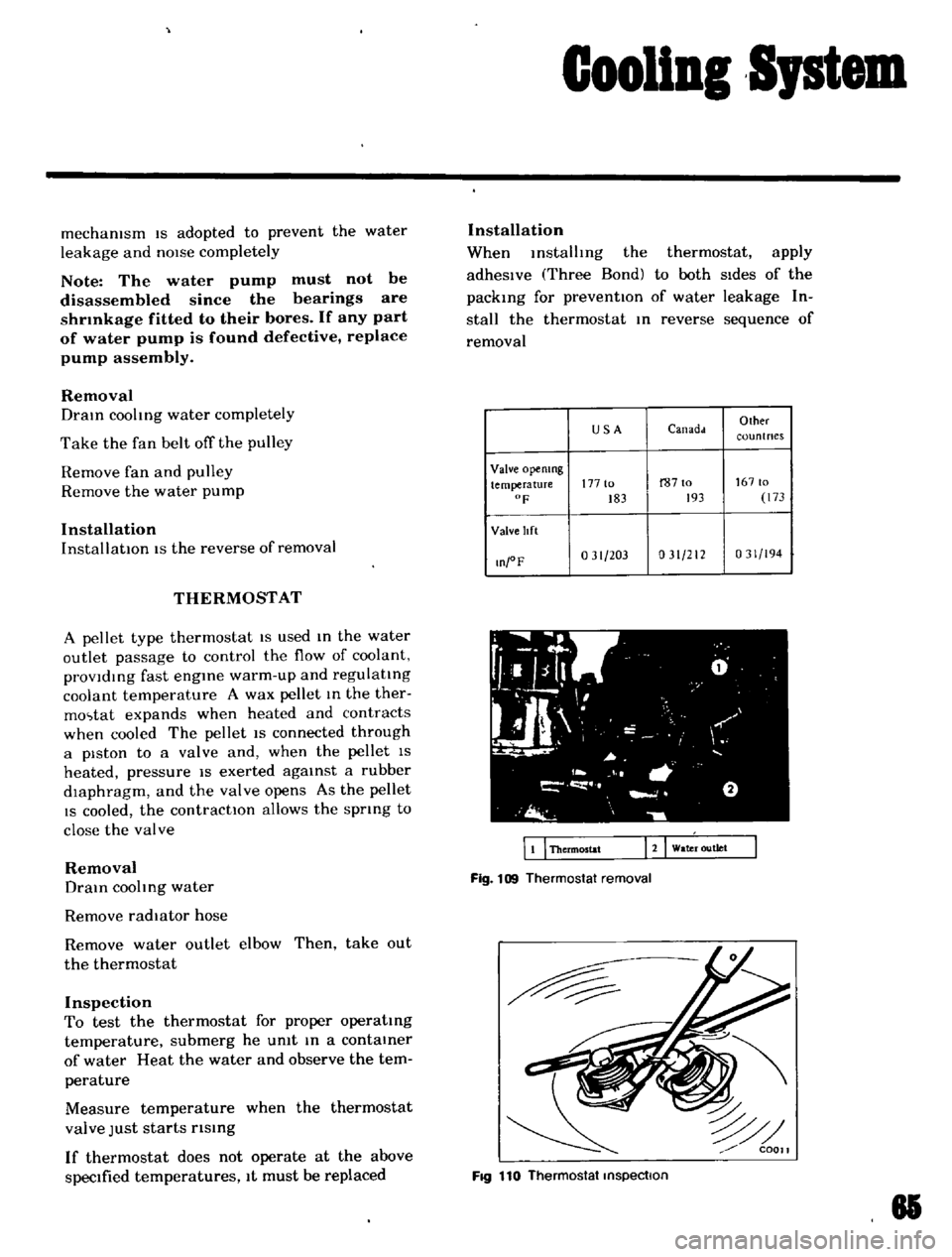
A
pellet
type
thermostat
IS
used
m
the
water
outlet
passage
to
control
the
flow
of
coolant
provldmg
fast
engme
warm
up
and
regulatmg
coolant
temperature
A
wax
pellet
m
the
ther
mo
tat
expands
when
heated
and
contracts
when
cooled
The
pellet
IS
connected
through
a
piston
to
a
valve
and
when
the
pellet
IS
heated
pressure
IS
exerted
agamst
a
rubber
dIaphragm
and
the
valve
opens
As
the
pellet
IS
cooled
the
contractIOn
allows
the
sprmg
to
close
the
valve
Removal
Dram
coohng
water
Remove
radiator
hose
Remove
water
outlet
elbow
Then
take
out
the
thermostat
Inspection
To
test
the
thermostat
for
proper
operatmg
temperature
submerg
he
umt
m
a
contamer
of
water
Heat
the
water
and
observe
the
tem
perature
Measure
temperature
when
the
thermostat
valve
Just
starts
rlsmg
If
thermostat
does
not
operate
at
the
above
specIfied
temperatures
It
must
be
replaced
Installation
When
mstalhng
the
thermostat
apply
adheSIve
Three
Bond
to
both
SIdes
of
the
packmg
for
preventIOn
of
water
leakage
In
stall
the
thermostat
m
reverse
sequence
of
removal
USA
Canadd
Olher
coun
t
nes
Valve
opemng
temperature
177
to
r8710
16710
F
183
193
173
Valve
lIft
O
oF
031
203
031
212
031
194
WI
fL
g
0
I
l
1
L
JI
I
I
I
I
a
J
i
o
wa
r
outlet
EI
Thermostat
Fig
109
Thermostat
removal
FIQ
110
Thermostat
inspection
81
Page 62 of 136
Gooliol
SJstem
RADIATOR
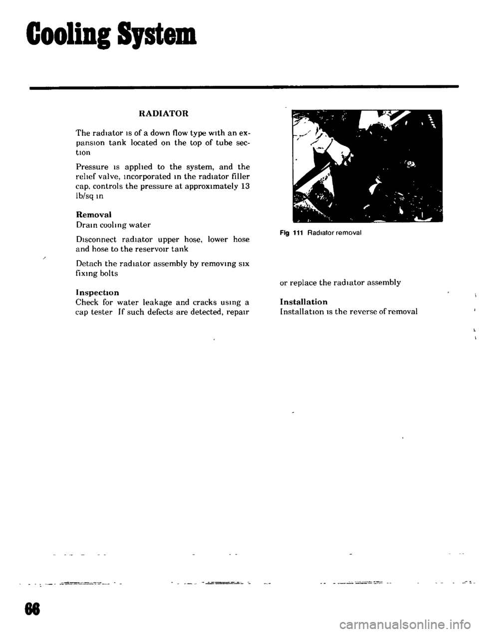
The
radiator
IS
of
a
down
flow
type
w1th
an
ex
panslOn
tank
located
on
the
top
of
tube
sec
tlOn
Pressure
IS
applted
to
the
system
and
the
I
eltef
valve
Incorporated
In
the
radiator
filler
cap
controls
the
pressure
at
approximately
13
Ib
sq
In
Removal
DraIn
cooltng
water
DIsconnect
radiator
upper
hose
lower
hose
and
hose
to
the
reservOir
tank
Detach
the
radiator
assembly
by
removmg
SIX
fiXIng
bolts
Inspection
Check
for
water
leakage
and
cracks
USIng
a
cap
tester
If
such
defects
are
detected
repair
88
Fig
111
Radiator
removal
or
replace
the
radIator
assembly
Installation
InstallatIOn
IS
the
reverse
of
removal
Page 63 of 136
Brakes
Jl
r7
I
J
I
lip
b
Ih
ih
p
lIJ
11
yhndu
blolk
2
Spnn
7
Air
hlu
k
r
12
PI
lon
3
LVI
pm
H
Rl
t
llmll
nn
13
lh
L
prm
hlm
8001
I
YOkl
pnn
5
lIJ
n
ll
prill
111
1
lon
Ii
15
Yoh
Fig
112
Front
diSC
brake
components
Movement
exceeding
the
elastic
dISplacement
IS
released
with
slipping
on
the
seal
surf
a
Returns
elastIC
displacement
of
the
seal
CYLINDER
SIDE
DECOMPRESSION
Fig
113
PIston
seal
automatic
adjusting
operation
FRONT
DISC
BRAKE
I
Brake
pad
2
Retalnl
pin
I
Clip
FIg
114
RemOVing
retaining
pm
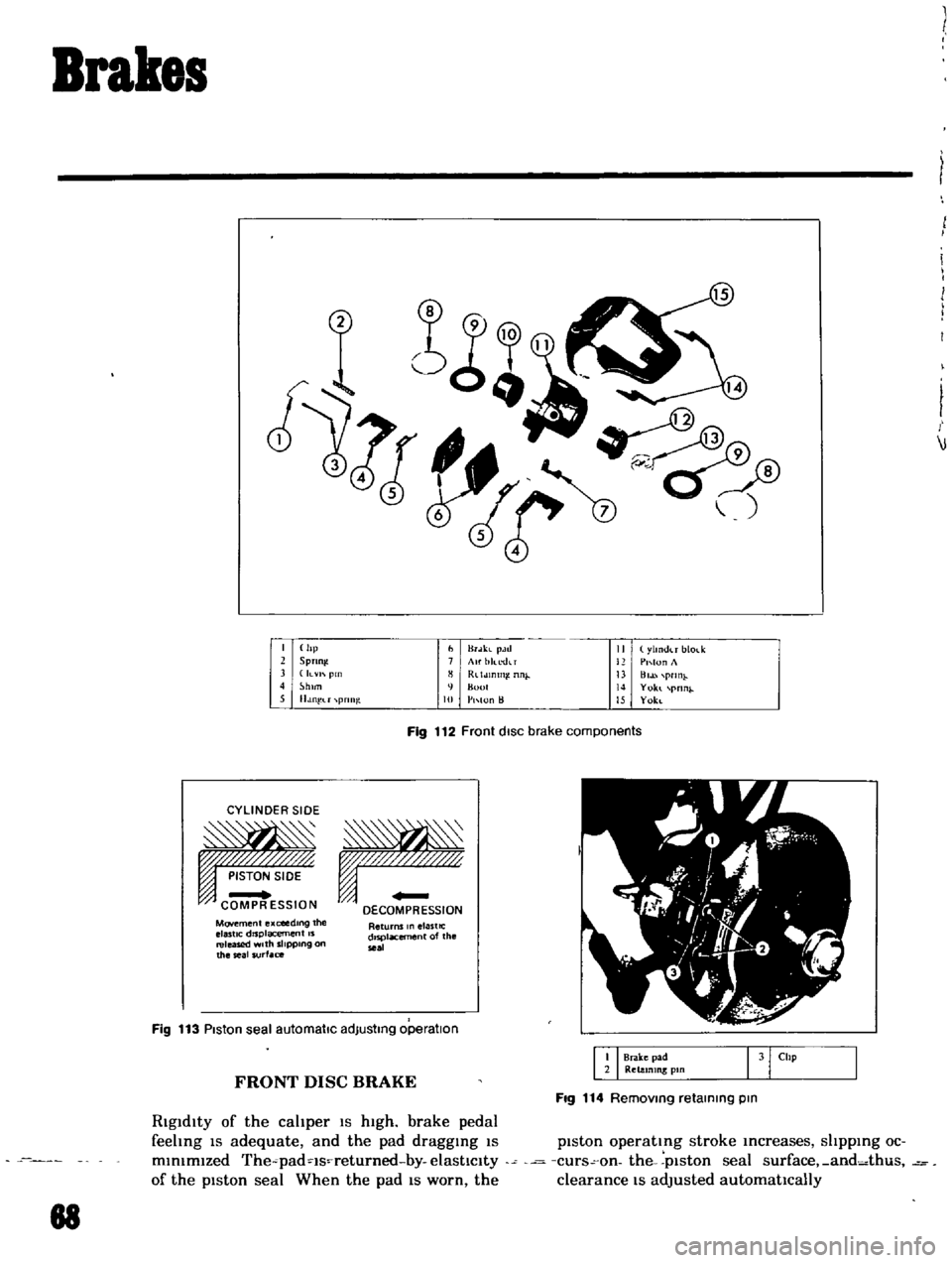
Rigidity
of
the
cahper
IS
high
brake
pedal
feehng
IS
adequate
and
the
pad
draggIng
IS
piston
operating
stroke
Increases
shpplng
oc
mlmmlzed
The
padqs
returned
by
elastIcity
curs
on
the
plston
seal
surface
and
thus
of
the
piston
seal
When
the
pad
IS
worn
the
clearance
IS
adjusted
automatIcally
88
Page 64 of 136
r
Brakes
Moreover
In
order
to
prevent
brake
squeahng
a
shIm
IS
Inserted
behind
the
pad
BRAKE
PAD
Replacement
Jack
up
front
UnIt
of
the
vehicle
and
remove
the
front
wheel
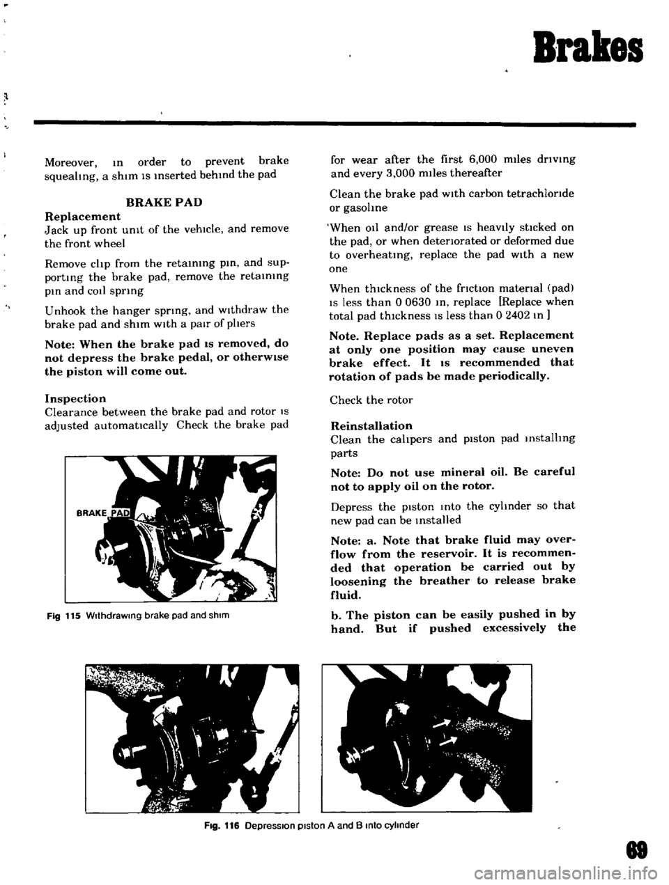
Remove
clip
from
the
retaining
pin
and
sup
porting
the
brake
pad
remove
the
retaining
pin
and
COil
spring
Unhook
the
hanger
spring
and
Withdraw
the
brake
pad
and
shim
With
a
pair
of
phers
Note
When
the
brake
pad
IS
removed
do
not
depress
the
brake
pedal
or
otherWise
the
piston
will
come
out
Inspection
Clearance
between
the
brake
pad
and
rotor
IS
adjusted
automatically
Check
the
brake
pad
Fig
115
WIthdraWing
brake
pad
and
shIm
for
wear
after
the
first
6
000
miles
driVing
and
every
3
000
miles
thereafter
Clean
the
brake
pad
With
carbon
tetrachloride
or
gasohne
When
011
and
or
grease
IS
heavIly
stlcked
on
the
pad
or
when
deteriorated
or
deformed
due
to
overheating
replace
the
pad
With
a
new
one
When
thickness
of
the
friction
material
pad
IS
less
than
0
0630
In
replace
Replace
when
total
pad
thIckness
IS
less
than
0
2402
In
Note
Replace
pads
as
a
set
Replacement
at
only
one
position
may
cause
uneven
brake
effect
It
IS
recommended
that
rotation
of
pads
be
made
periodically
Check
the
rotor
Reinstallation
Clean
the
calipers
and
piston
pad
installing
parts
Note
Do
not
use
mineral
oil
Be
careful
not
to
apply
oil
on
the
rotor
Depress
the
pIston
Into
the
cyhnder
so
that
new
pad
can
be
Installed
Note
a
Note
that
brake
fluid
may
over
flow
from
the
reservoir
It
is
recommen
ded
that
operation
be
carried
out
by
loosening
the
breather
to
release
brake
fluid
b
The
piston
can
be
easily
pushed
in
by
hand
But
if
pushed
excessively
the
Fig
116
DepreSSion
piston
A
and
B
Into
cylinder
88
Page 65 of 136
Brakes
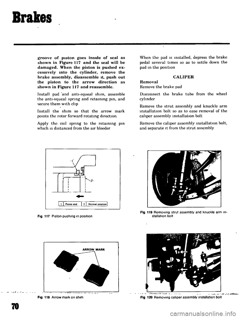
groove
of
pIston
goes
insIde
of
seal
as
shown
in
Figure
117
and
the
seal
will
be
damaged
When
the
piston
is
pushed
ex
cesslvely
mto
the
cylinder
remove
the
brake
assembly
disassemble
It
push
out
the
piston
to
the
arrow
direction
as
shown
in
Figure
117
and
reassemble
Install
pad
and
antt
squeal
shim
assemble
the
anti
squeal
spring
and
retaining
pin
and
ecure
them
with
cltp
Install
the
shim
so
that
the
arrow
mark
pOints
the
rotor
forward
rotating
directIOn
Apply
the
COIl
spring
to
the
retaining
pin
which
IS
distanced
from
the
atr
bleeder
111
PlSton
seal
I
2
I
Normal
position
I
Fig
117
Piston
pushIng
In
posllIon
FIg
118
Arrow
mark
on
shim
78
When
the
pad
IS
Installed
depress
the
brake
pedal
several
tl
mes
so
as
to
settle
down
the
pad
In
the
posltton
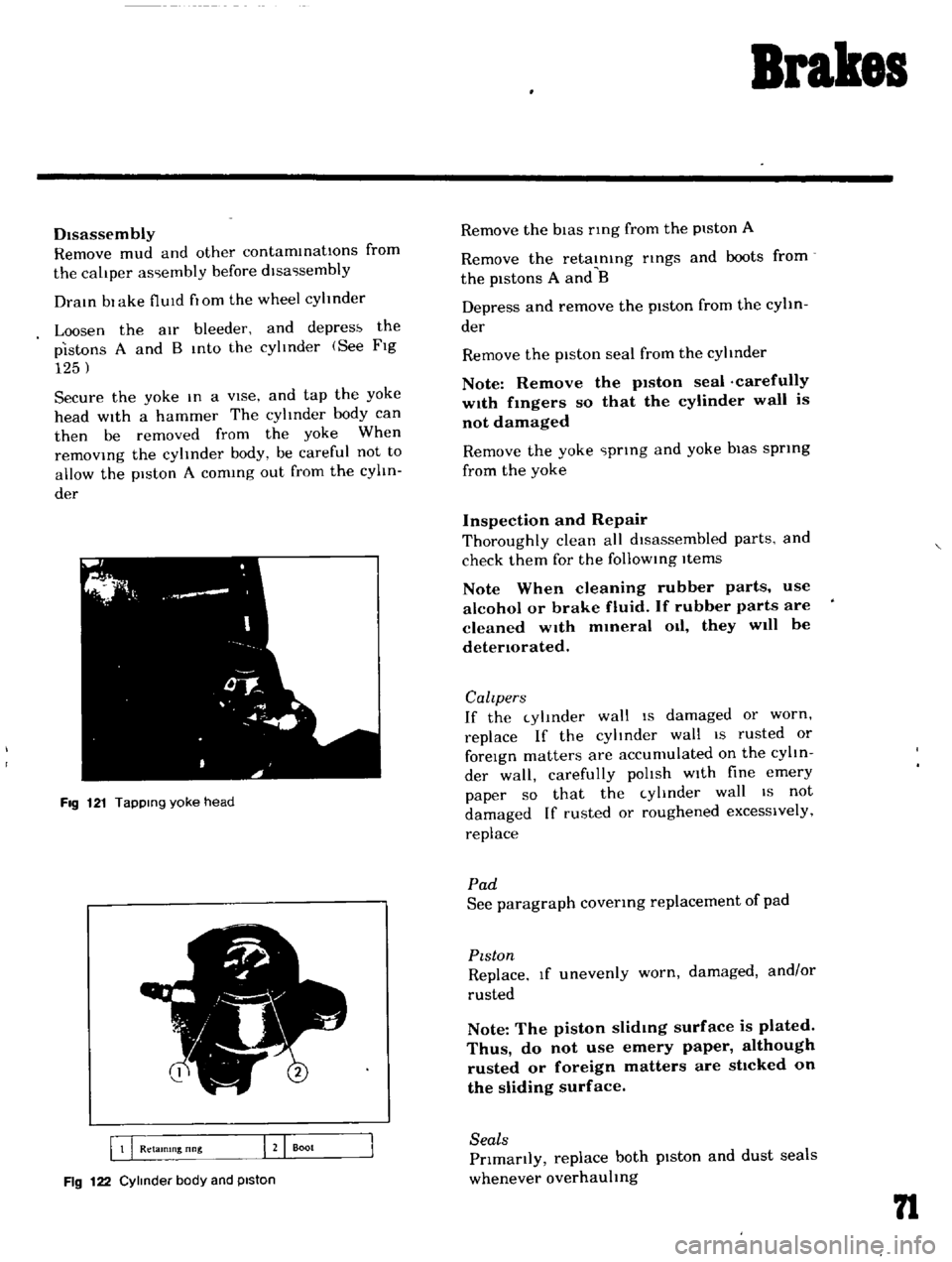
CALIPER
Removal
Remove
the
brake
pad
DIsconnect
the
brake
tube
from
the
wheel
cyltnder
Remove
the
strut
assembly
and
knuckle
arm
installatIOn
bolt
so
as
to
ease
removal
of
the
cahper
assembly
installatIOn
bolt
Remove
the
cahper
assembly
installatIOn
bolt
and
separate
It
from
the
strut
assembly
Fig
119
RemOVing
strut
assembly
and
knuckle
arm
in
stallatIon
bolt
Fig
120
RemOVing
caliper
assembly
Installallon
bolt
Page 66 of 136
Brakes
DIsassembly
Remove
mud
and
other
contamInations
from
the
caLiper
as
embly
before
dlsa
sembly
DraIn
bl
ake
fluId
flOm
the
wheel
cylinder
Loosen
the
aIr
bleeder
and
depres
the
pistons
A
and
B
Into
the
cylInder
See
FIg
125
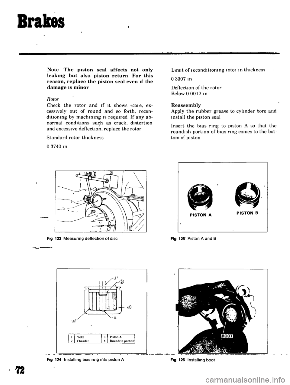
Secure
the
yoke
In
a
vIse
and
tap
the
yoke
head
with
a
hammer
The
cylinder
body
can
then
be
removed
from
the
yoke
When
remOVIng
the
cylinder
body
be
careful
not
to
allow
the
piston
A
comIng
out
from
the
cylIn
der
FIg
121
TapPing
yoke
head
5
I
B
Q
Retamlng
nng
J
Boot
Fig
122
Cylinder
body
and
piston
Remove
the
bIas
nng
from
the
piston
A
Remove
the
retaInIng
nngs
and
boots
from
the
pistons
A
and
B
Depress
and
remove
the
piston
from
the
cylin
der
Remove
the
piston
seal
from
the
cylinder
Note
Remove
the
p1ston
seal
carefully
w1th
fmgers
so
that
the
cylinder
wall
is
not
damaged
Remove
the
yoke
prIng
and
yoke
bias
sprIng
from
the
yoke
Inspection
and
Repair
Thoroughly
clean
all
dIsassembled
parts
and
check
them
for
the
follOWIng
Items
Note
When
cleaning
rubber
parts
use
alcohol
or
brake
fluid
If
rubber
parts
are
cleaned
wIth
mmeral
Oil
they
will
be
detenorated
Calzpers
If
the
cylInder
wall
IS
damaged
or
worn
replace
If
the
cylinder
wall
IS
rusted
or
foreIgn
matters
are
accumulated
on
the
cylIn
der
wall
carefully
polIsh
wIth
fine
emery
paper
so
that
the
cylInder
wall
IS
not
damaged
If
rusted
or
roughened
excessively
replace
Pad
See
paragraph
covenng
replacement
of
pad
PIston
Replace
If
unevenly
worn
damaged
and
or
rusted
Note
The
piston
slidmg
surface
is
plated
Thus
do
not
use
emery
paper
although
rusted
or
foreign
matters
are
sttcked
on
the
sliding
surface
Seals
Prlmanly
replace
both
pIston
and
dust
seals
whenever
overhauling
n
Page 67 of 136
Brakes
Note
The
piston
seal
affects
not
only
Ieakmg
but
also
piston
return
For
this
reason
replace
the
piston
seal
even
If
the
damage
IS
minor
Rotor
Check
the
rotor
and
If
It
shows
cOl
e
ex
cesslvely
out
of
round
and
so
forth
recon
ditIOnIng
by
machInIng
l
l
requIred
If
any
ab
normal
condItIOns
such
as
crack
dl
ltortlOn
and
excessIve
deflectIOn
replace
the
rotor
Standard
rotor
thlckne
ls
03740
In
Fig
123
MeaSUring
deflectoon
of
diSC
Fig
124
Installing
bias
ring
mto
piston
A
72
LImIt
of
I
econdltlOntng
lotOl
In
thlcknes
l
o
3307
In
DeflectIOn
of
the
rotor
Below
0
0012
In
Reassembly
Apply
the
rubber
grea
le
to
cylinder
bore
and
Install
the
pIston
seal
Insert
the
bIas
rIng
to
pIston
A
so
that
the
roundl
lh
portIon
of
bIas
ring
comes
to
the
bot
tom
of
pIston
A
PISTON
B
PISTON
A
Fig
125
Piston
A
and
B
Fig
126
Installing
boot
Page 68 of 136
Brakes
Note
Be
careful
not
to
confuse
the
piston
A
with
B
Apply
rubber
grease
hghtly
to
the
shdlng
par
tlon
of
p1ston
and
Insert
the
piston
Into
the
cyhnder
Note
When
insertmg
the
piston
be
careful
not
to
insert
too
far
Install
the
boot
and
retaining
nng
Install
so
that
the
yoke
groove
of
bIas
nng
of
piston
A
COinCide
wIth
the
yoke
groove
of
cyhnder
YOKE
SPRING
Fig
127
Installation
of
yoke
spnng
1
Fig
128
InstallatIOn
of
yoke
spnng
2
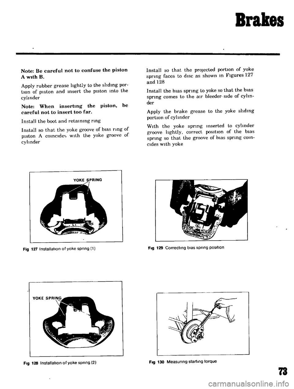
Install
so
that
the
projected
portIOn
of
yoke
spnng
faces
to
diSC
as
shown
In
Figures
127
and
128
Install
the
bias
spring
to
yoke
so
that
the
bias
spring
comes
to
the
aIr
bleeder
Side
of
cyhn
der
Apply
the
brake
grease
to
the
yoke
shdlng
portIOn
of
cylinder
With
the
yoke
spring
Inserted
to
cylinder
groove
hghtly
correct
poSitIOn
of
the
bias
spnng
so
that
the
groove
of
biaS
spring
COin
Cides
With
yoke
Fig
129
Correctmg
bias
spnng
POSItion
Fig
130
Measunng
startmg
torque
73
Page 69 of 136
Brakes
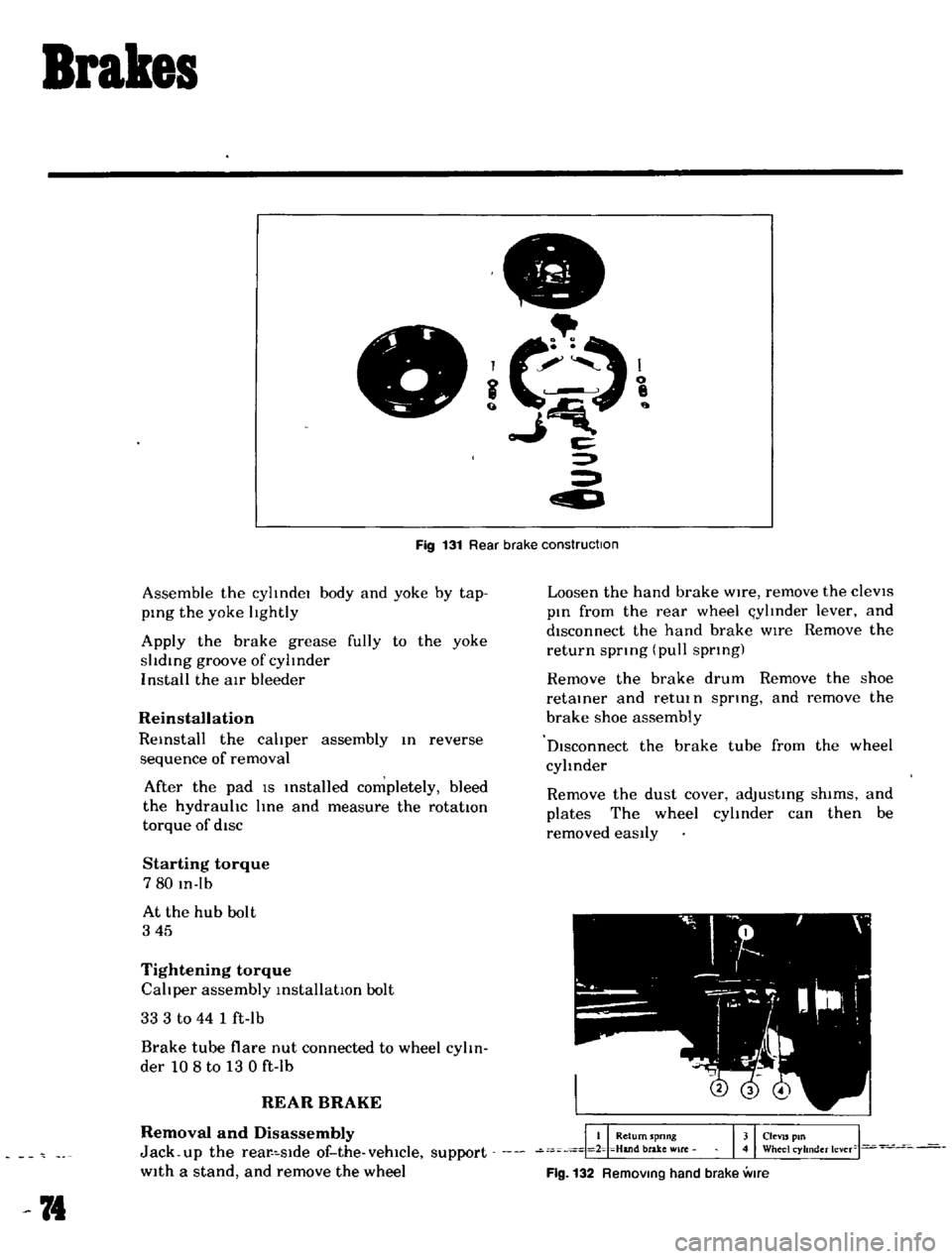
c
Fig
131
Rear
brake
construction
Assemble
the
cylIndel
body
and
yoke
by
tap
ping
the
yoke
lIghtly
Apply
the
brake
grease
fully
to
the
yoke
slIding
groove
of
cylInder
I
nstall
the
air
bleeder
Reinstallation
Reinstall
the
calIper
assembly
In
reverse
sequence
of
removal
After
the
pad
IS
Installed
completely
bleed
the
hydraulIc
line
and
measure
the
rotatton
torque
of
diSC
Starting
torque
780
In
Ib
At
the
hub
bolt
345
Tightening
torque
CalIper
assembly
installatIOn
bolt
33
3
to
44
1
ft
lb
Brake
tube
flare
nut
connected
to
wheel
cylIn
der
108
to
13
0
ft
lb
REAR
BRAKE
Removal
and
Disassembly
Jack
up
the
rear
slde
of
the
vehicle
support
With
a
stand
and
remove
the
wheel
74
Loosen
the
hand
brake
Wire
remove
the
cleVIS
pin
from
the
rear
wheel
l
ylInder
lever
and
disconnect
the
hand
brake
wIre
Remove
the
return
spnng
pull
spnng
Remove
the
brake
drum
Remove
the
shoe
retainer
and
retUl
n
spnng
and
remove
the
brake
shoe
assembly
DIsconnect
the
brake
tube
from
the
wheel
cylinder
Remove
the
dust
cover
adjusting
shims
and
plates
The
wheel
cylInder
can
then
be
removed
eaSily
Flg
132
RemOVing
hand
brake
vme
Page 70 of 136
Brakes
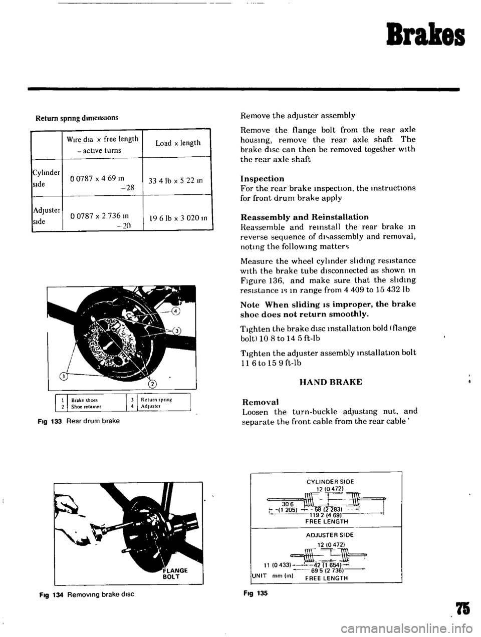
Return
spnng
dimensIOns
Wire
dla
x
free
length
Load
x
length
actIve
turns
Cylmder
o
0787
x
4
69
III
sIde
33
4lb
x
5
22
m
28
Adjuster
00787
x
2
736
m
sIde
19
6
lb
x
3
020
III
20
1
Brake
moes
2
Shoe
retamer
Fig
133
Rear
drum
brake
Fig
134
Removmg
brake
disc
Remove
the
adjuster
assembly
Remove
the
flange
bolt
from
the
rear
axle
housing
remove
the
rear
axle
shaft
The
brake
disc
can
then
be
removed
together
wIth
the
rear
axle
shaft
Inspection
For
the
rear
brake
inspectIOn
the
instructIOns
for
front
drum
brake
apply
Reassembly
and
Reinstallation
Rea
semble
and
reinstall
the
rear
brake
In
reverse
sequence
of
dl
assembly
and
removal
noting
the
follOWing
matter
Measure
the
wheel
cylinder
shdlng
resistance
With
the
brake
tube
dIsconnected
as
shown
In
Figure
136
and
make
sure
that
the
slIding
resIstance
1
In
range
from
4
409
to
15432
Ib
Note
When
sliding
IS
improper
the
brake
shoe
does
not
return
smoothly
Tighten
the
brake
diSC
installatIOn
bold
flange
bolt
10
8
to
14
5
ft
Ib
T1ghten
the
adjuster
assembly
installatIOn
bolt
116to
159ft
Ib
HAND
BRAKE
Removal
Loosen
the
turn
buckle
adjusting
nut
and
separate
the
front
cable
from
the
rear
cable
CYLINDER
SIDE
306
j
E
i
1
205
58
2
283
J
1192
469
FREE
LENGTH
ADJUSTE
R
51
DE
12
0472
2
11
0433
42
1654
69
5
2
736
UNIT
mm
0
FREE
LENGTH
Fig
135
75