DATSUN B110 1973 Service Repair Manual
Manufacturer: DATSUN, Model Year: 1973, Model line: B110, Model: DATSUN B110 1973Pages: 513, PDF Size: 28.74 MB
Page 411 of 513
ENGINE
Y
Q
0
Fig
EF
34
Disassembling
accelerator
pump
and
hi
metal
cover
1
EC013
Fig
EF
35
Removing
throttle
chamber
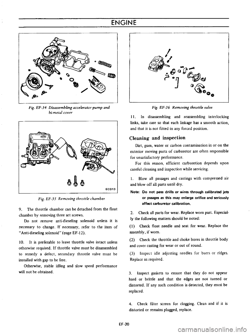
9
The
throttle
chamber
can
be
detached
from
the
float
chamber
by
removing
three
set
screws
Do
not
remove
anti
dieseling
solenoid
unless
it
is
necessary
to
change
If
necessary
refer
to
the
item
of
Anti
dieseling
solenoid
page
EF
12
10
It
is
preferable
to
leave
throttle
valve
intact
unless
otherwise
required
If
throttle
valve
must
be
disassembled
to
remedy
a
defect
secondary
throttle
valve
must
be
installed
with
gap
to
be
free
Otherwise
stable
idling
and
slow
speed
performance
will
not
be
obtained
I
o
rJ
01
o
o
Fig
EF
36
Removing
throttle
valve
II
In
disassembling
and
reassembling
interlocking
links
take
care
so
that
each
linkage
has
a
smooth
action
and
that
it
is
not
fitted
in
any
forced
position
Cleaning
and
inspection
Dirt
gum
water
or
carbon
contamination
in
or
on
the
exterior
moving
parts
of
carburetor
are
often
responsible
for
unsatisfactory
performance
For
this
reason
efficient
carburetion
depends
upon
careful
cleaning
and
inspection
while
servicing
1
Blow
aU
passages
and
castings
with
compressed
air
and
blow
off
all
parts
until
dry
Note
Do
not
pass
drills
or
wires
through
calibrated
jets
or
pssages
as
this
may
enlarge
orifice
and
seriously
affect
carburetor
calibration
2
Check
all
parts
for
wear
Replace
worn
part
Especial
ly
the
following
matters
should
be
noted
I
Check
float
needle
and
seat
for
wear
Replace
the
assembly
if
worn
2
Check
the
throttle
and
choke
bores
in
throttle
body
and
cover
casting
for
wear
or
out
of
round
3
Inspect
idle
adjusting
needles
fur
burrs
or
ridges
Replace
as
required
3
Inspect
gaskets
to
ensure
that
they
do
not
appear
hard
or
brittle
and
that
the
edges
are
not
turned
or
distorted
If
any
such
condition
is
detected
they
must
be
replaced
4
Check
fIlter
screen
for
clogging
Clean
and
if
it
is
distorted
or
remains
plugged
replace
EF
20
Page 412 of 513
FUEL
SYSTEM
5
Check
venturi
clusters
for
loose
or
worn
parts
If
damage
or
looseness
exists
replace
cluster
assembly
6
Check
the
linkage
for
operating
condition
7
Inspect
the
operation
of
accelerating
pump
Pour
gasoline
into
the
float
chamber
and
operate
the
throttle
lever
Check
condition
of
gasoline
injection
from
the
accelerating
nozzle
Assembly
and
instalIetion
Assemble
and
install
the
carburetor
in
reverse
sequence
of
disassembly
and
removal
Replace
the
gaskets
if
necessary
When
disassembling
and
reassembling
the
interlock
link
and
related
components
be
careful
not
to
bend
or
deform
SPECIFICATIONS
AND
SERVICE
DATA
Carburetor
model
Applied
engine
Type
Outlet
diameter
mm
in
rom
in
Venturi
diameter
Main
jet
Main
air
bleed
Slow
jet
Slow
air
bleed
Power
jet
Float
level
H
rom
in
Interlock
opening
of
primary
and
secondary
throttle
valve
G
I
Throttle
valve
opening
480
mm
in
Auto
choke
Fast
idle
setting
clearance
A
mm
in
Manual
transmission
Automatic
transmission
Vacuum
break
gap
between
choke
valve
and
carburetor
body
8
mm
in
Manual
transmission
Automatic
transmission
EF
21
the
components
Reassembly
carefully
and
correctly
so
that
all
interlock
links
operate
smoothly
JETS
The
carburetor
performance
depends
on
jets
and
air
bleeds
and
the
vehicle
emissions
largely
depends
on
the
carburetor
performance
That
is
why
these
components
are
manufactured
with
utmost
care
To
clean
them
use
gasoline
and
blow
air
on
them
Changing
jet
or
air
bleed
size
may
cause
ill
vehicle
emission
So
they
should
not
be
changed
their
numbers
DCH3064
for
Manual
transmission
DCH306
5
for
Automatic
transmission
Downdraft
Primary
Secondary
26
1
024
30
1
181
20
0
787
26
1
024
1
95
1
140
1
80
1
80
1
43
1
50
1
215
1
100
1
60
18
to
20
0
709
to
0
748
5
8
0
2283
0
80
to
0
88
0
0315
to
0
0346
1
07
to
1
17
0
0421
to
0
0461
1
140
to
1
260
0
0449
to
0
0496
1
205
to
1
335
0
0474
to
0
0526
Page 413 of 513
ENGINE
Choke
unloader
clearance
carburetor
body
C
between
choke
valve
and
mm
in
Bi
metal
resistance
ohms
2
01
0
07911
8
6t09
0
Accelerator
pump
Injector
hole
Return
spring
Fuel
pressure
mm
in
g
mm
Ib
in
kg
cm
2
psi
kg
lb
0
5
0
0197
78
I
I
0
18
2
6
Manual
transmission
Automatic
transmission
Weight
2
8
6
2
2
9
6
39
Example
1
215
represents
215
100
2
15
mm
0
0846
in
diameter
TROUBLE
DIAGNOSES
AND
CORRECTIONS
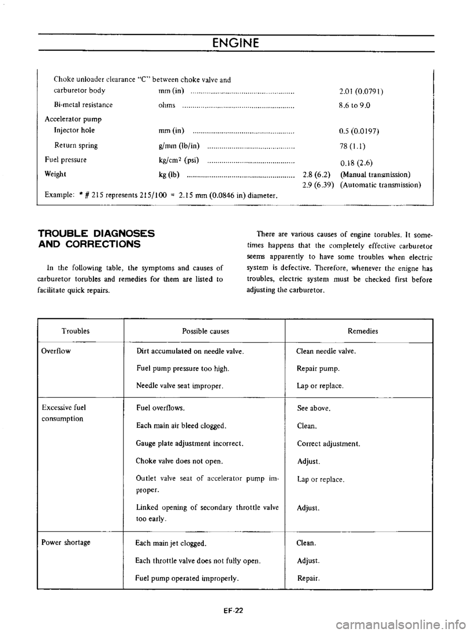
There
are
various
causes
of
engine
tarubles
It
some
times
happens
that
the
completely
effective
carburetor
seems
apparently
to
have
some
troubles
when
electric
system
is
defective
Therefore
whenever
the
enigne
has
troubles
electric
system
must
be
checked
first
before
adjusting
the
carburetor
In
the
following
table
the
symptoms
and
causes
of
carburetor
tarubles
and
remedies
for
them
are
listed
to
facilitate
quick
repairs
Troubles
Possible
causes
Remedies
Overflow
Dirt
accumulated
on
needle
valve
Clean
needle
valve
Fuel
pump
pressure
too
high
Repair
pump
Needle
valve
seat
improper
Lap
or
replace
Excessive
fuel
consumption
Fuel
overflows
See
above
Each
main
air
bleed
clogged
Clean
Gauge
plate
adjustment
incorrect
Correct
adjustment
Choke
valve
does
not
open
Adjust
Outlet
valve
seat
of
accelerator
pump
im
proper
Lap
or
replace
Linked
opening
of
secondary
throttle
valve
too
early
Adjust
Power
shortage
Each
main
jet
clogged
Clean
Each
throttle
valve
does
not
fully
open
Adjust
Fuel
pump
operated
improperly
Repair
EF
22
Page 414 of 513
Troubles
Improper
idling
Rough
engine
idle
or
engine
stop
Engine
idle
too
fast
Engine
hesitation
FUEl
SYSTEM
Possible
causes
ruel
strainer
clogged
Vacuum
jet
clogged
Power
valve
operated
improperly
Slow
jet
clogged
Each
throttle
valve
does
not
close
Secondary
throttle
valve
operated
im
properly
Each
throttle
valve
shaft
wear
Packing
between
manifold
and
carburetor
defective
Fuel
overflows
Incorrect
carburetor
adjustment
idle
speed
idle
mixture
choke
setting
Incorrect
basic
ignition
timing
Incorrect
automatic
temperature
control
air
cleaner
Defect
or
malfunction
of
ignition
system
spark
plug
high
tension
cable
breaker
point
ignition
coil
etc
Trouble
in
throttle
link
and
cable
Incorrect
throttle
opener
adjustment
Trouble
in
PCV
valve
Trouble
in
automatic
choke
Defect
or
malfunction
of
ignition
system
spark
plug
high
tension
cable
breaker
point
ignition
coil
etc
Each
main
jet
slow
jet
clogged
By
pass
hole
idle
passage
clogged
Emulsion
tube
clogged
EF
23
Remedies
Clean
Clean
Adjust
Clean
Adjust
Overhaul
and
clean
Replace
Replace
tightening
See
the
first
item
Adjust
idle
speed
mixture
and
timing
Adjust
ignition
timing
Adjust
automatic
temperature
control
air
cleaner
Adjust
or
replace
ignition
system
Check
throttle
link
and
cable
Adjust
throttle
opener
Replace
PCV
valve
Adjust
auotmatic
choke
Adjust
or
replace
ignition
system
Clean
Clean
tube
Clean
Page 415 of 513
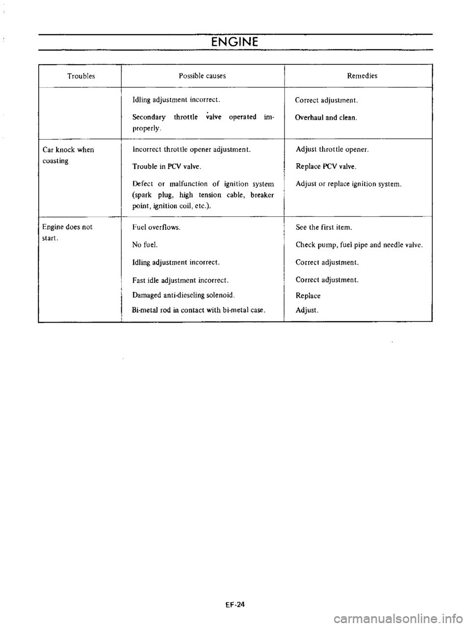
Troubles
Car
knock
when
coasting
Engine
does
not
start
ENGINE
Possible
causes
Idling
adjustment
incorrect
Secondary
throttle
valve
operated
im
properly
Incorrect
throttle
opener
adjustment
Trouble
in
PCV
valve
Defect
or
malfunction
of
ignition
system
spark
plug
high
tension
cable
breaker
point
ignition
coil
etc
Fuel
overflows
No
fu
el
Idling
adjustment
incorrect
Fast
idle
adjustment
incorrect
Damaged
anti
dieseling
solenoid
Bi
metal
rod
in
contact
with
hi
metal
case
EF
24
Remedies
Correct
adjustment
Overhaul
and
clean
Adjust
throttle
opener
Replace
PCV
valve
Adjust
or
replace
ignition
system
See
the
first
item
Check
pump
fuel
pipe
and
needle
valve
Correct
adjustment
Correct
adjustment
Replace
Adjust
Page 416 of 513
FUEl
SYSTEM
EVAPORATIVE
EMISSION
CONTROL
SYSTEM
CONTENTS
OESCRI
PTION
Flow
guide
valve
MAINTENANCE
AND
TESTING
Checking
fuel
tank
vapor
liquid
separator
and
vapor
vent
I
ins
EF
25
EF
26
EF
26
EF
26
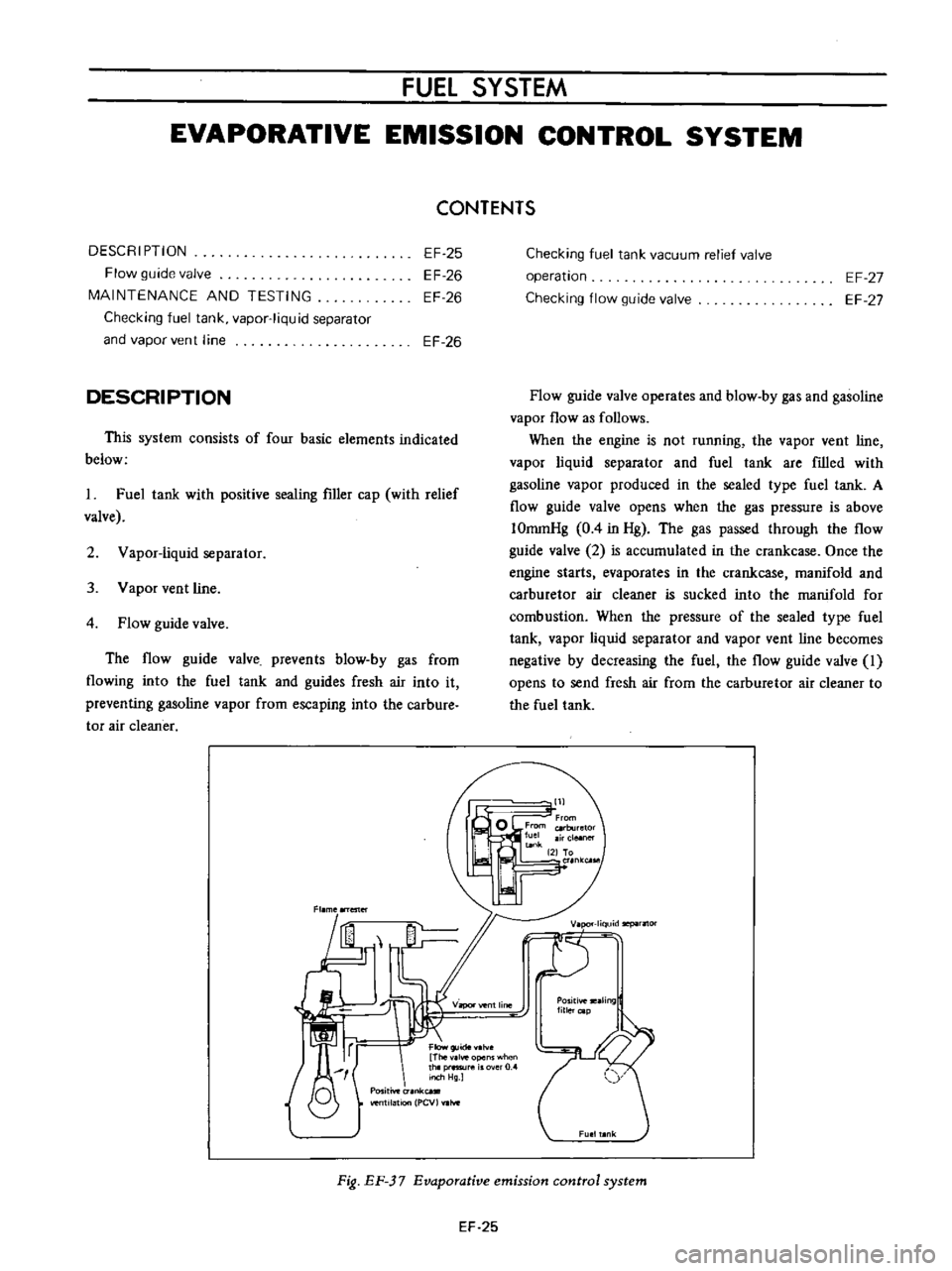
DESCRIPTION
This
system
consists
of
four
basic
elements
indicated
below
I
Fuel
tank
with
positive
sealing
filler
cap
with
relief
valve
2
Vapor
liquid
separator
3
Vapor
vent
line
4
Flow
guide
valve
The
flow
guide
valve
prevents
blow
by
gas
from
flowing
into
the
fuel
tank
and
guides
fresh
air
into
it
preventing
gasoline
vapor
from
escaping
into
the
carbure
tor
air
cleaner
Fl
me
ester
I
f
Flow
Thev
lve
opens
when
thlp
1l
rO
Inch
Hg
O
Positive
unk
venlI1atlon
PCV
hoe
Checking
fuel
tank
vacuum
relief
valve
operation
Checking
flow
guide
valve
EF
27
EF
27
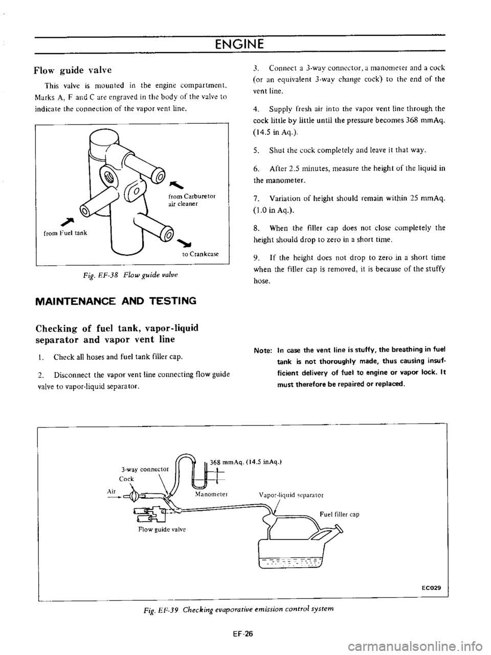
Flow
guide
valve
operates
and
blow
by
gas
and
gasoline
vapor
flow
as
follows
When
the
engine
is
not
running
the
vapor
vent
line
vapor
liquid
separator
and
fuel
tank
are
filled
with
gasoline
vapor
produced
in
the
sealed
type
fuel
tank
A
flow
guide
valve
opens
when
the
gas
pressure
is
above
IOromHg
0
4
in
Hg
The
gas
passed
through
the
flow
guide
valve
2
is
accumulated
in
the
crankcase
Once
the
engine
starts
evaporates
in
the
crankcase
manifold
and
carburetor
air
cleaner
is
sucked
into
the
manifold
for
combustion
When
the
pressure
of
the
sealed
type
fuel
tank
vapor
liquid
separator
and
vapor
vent
line
becomes
negative
by
decreasing
the
fuel
the
flow
guide
valve
I
opens
to
send
fresh
air
from
the
carburetor
air
cleaner
to
the
fuel
tank
lill
K
riquidllepilrflOr
T
VilPOl
vent
line
Positiveteilling
lillercap
Fig
EF
37
Evaporative
emission
control
system
EF
25
Page 417 of 513
ENGINE
ffi68
mmAq
14
5
mAq
3
way
connector
Cock
II
M
nam
e
Flow
guide
valve
This
valve
is
mounted
in
the
engine
compartment
f
tHks
A
F
and
C
are
engraved
in
the
body
of
the
valve
to
indicate
the
connection
of
the
vapor
vent
line
l
l
1
from
Fuel
tank
to
Crankcase
Fig
EF
3B
Flow
guide
valve
MAINTENANCE
AND
TESTING
Checking
of
fuel
tank
vapor
liquid
separator
and
vapor
vent
line
Check
all
hoses
and
fuel
tank
filler
cap
2
Disconnect
the
vapor
vent
line
connecting
flow
guide
valve
to
vapor
liquid
separator
Flow
guide
valve
3
Connect
a
J
way
connector
a
manometer
and
a
l
ul
k
or
an
equivalent
3
wav
change
cock
to
the
end
of
the
vent
line
4
Supply
fresh
air
into
the
vapor
vent
line
through
the
cock
little
by
little
until
the
pressure
becomes
368
romAq
14
5
in
Aq
5
Shut
the
cock
completely
and
leave
it
that
way
6
After
2
5
minutes
measure
the
height
uf
the
liquid
in
the
manometer
7
Variation
of
height
should
remain
within
25
mmAq
1
0
in
Aq
8
When
the
filler
cap
does
not
close
completely
the
height
should
drop
to
zero
in
a
short
time
9
I
f
the
height
docs
not
drop
to
zero
in
a
short
time
when
the
filler
cap
is
removed
it
is
because
of
the
stuffy
hose
Note
In
case
the
vent
line
is
stuffy
the
breathing
in
fuel
tank
is
not
thoroughly
made
thus
causing
insuf
ficient
delivery
of
fuel
to
engine
or
vapor
lock
It
must
therefore
be
repaired
or
replaced
1
m
eparator
1
Fuel
filler
cap
Y
XI
EC029
Fig
EF
39
Checking
evaporative
emission
control
system
EF
26
Page 418 of 513
FUEL
SYSTEM
Checking
fuel
tank
vacuum
relief
valve
operation
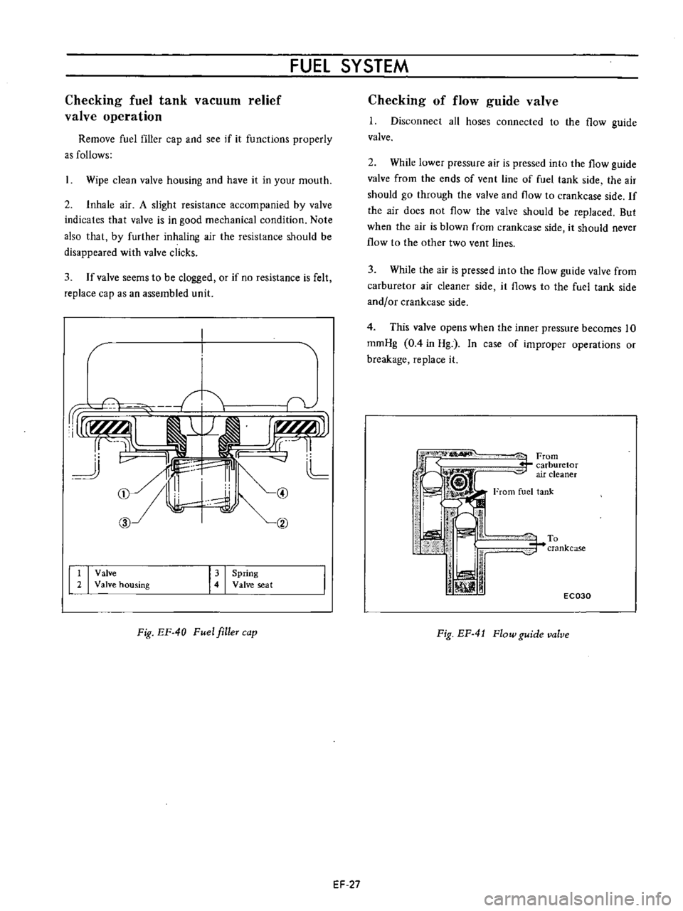
Remove
fuel
filler
cap
and
see
if
it
functions
properly
as
follows
Wipe
clean
valve
housing
and
have
it
in
your
mouth
2
Inhale
air
A
slight
resistance
accompanied
by
valve
indicates
that
valve
is
in
good
mechanical
condition
Note
also
that
by
further
inhaling
air
the
resistance
should
be
disappeared
with
valve
clicks
3
If
valve
seems
to
be
clogged
or
if
no
resistance
is
felt
replace
cap
as
an
assembled
unit
1
1
1I
L
CD
hl
cv
CID
t
I
Valve
2
Valve
housing
I
I
Spring
Valve
seat
Fig
EF
40
Fuel
filleT
cap
EF
27
Checking
of
flow
guide
valve
1
Disconnect
all
hoses
connected
to
the
flow
guide
valve
2
While
lower
pressure
air
is
pressed
into
the
flow
guide
valve
from
the
ends
of
vent
line
of
fuel
tank
side
the
air
should
go
through
the
valve
and
flow
to
crankcase
side
If
the
air
does
not
flow
the
valve
should
be
replaced
But
when
the
air
is
blown
from
crankcase
side
it
should
never
flow
to
the
other
two
vent
lines
3
While
the
air
is
pressed
into
the
flow
guide
valve
from
carburetor
air
cleaner
side
it
flows
to
the
fuel
tank
side
and
or
crankcase
side
4
This
valve
opens
when
the
inner
pressure
becomes
10
romHg
0
4
in
Hg
In
case
of
improper
operations
or
breakage
replace
it
iFrom
r
carburetor
air
cleaner
From
fuel
tank
To
r
crankcase
j
iJ
i
ill
1
1
EC030
Fig
EF
4
J
Flow
guide
valve
Page 419 of 513
DATE
ENGINE
SERVICE
JOURNAL
OR
BULLETIN
REFERENCE
JOURNAL
or
BULLETIN
No
PAGE
No
SUBJECT
EF
28
Page 420 of 513
DATSUN
1200
MODEL
B
11
0
SERIES
L
NISSAN
I
NISSAN
MOTOR
CO
LTD
TOKYO
JAPAN
SECTION
EE
ENGINE
ELECTRICAL
SYSTEM
BATTERY
STARTING
MOTOR
CHARGING
CIRCUIT
ALTERNATOR
REGULATOR
IGNITIO
N
CIRCUIT
DISTRIBUTOR
IGNITION
COIL
SPARK
PLUG
EEl
EE
3
EE
15
EE
16
EE
23
EE
29
EE
29
EE
36
EE
37