charging DATSUN PICK-UP 1977 Service Manual
[x] Cancel search | Manufacturer: DATSUN, Model Year: 1977, Model line: PICK-UP, Model: DATSUN PICK-UP 1977Pages: 537, PDF Size: 35.48 MB
Page 146 of 537
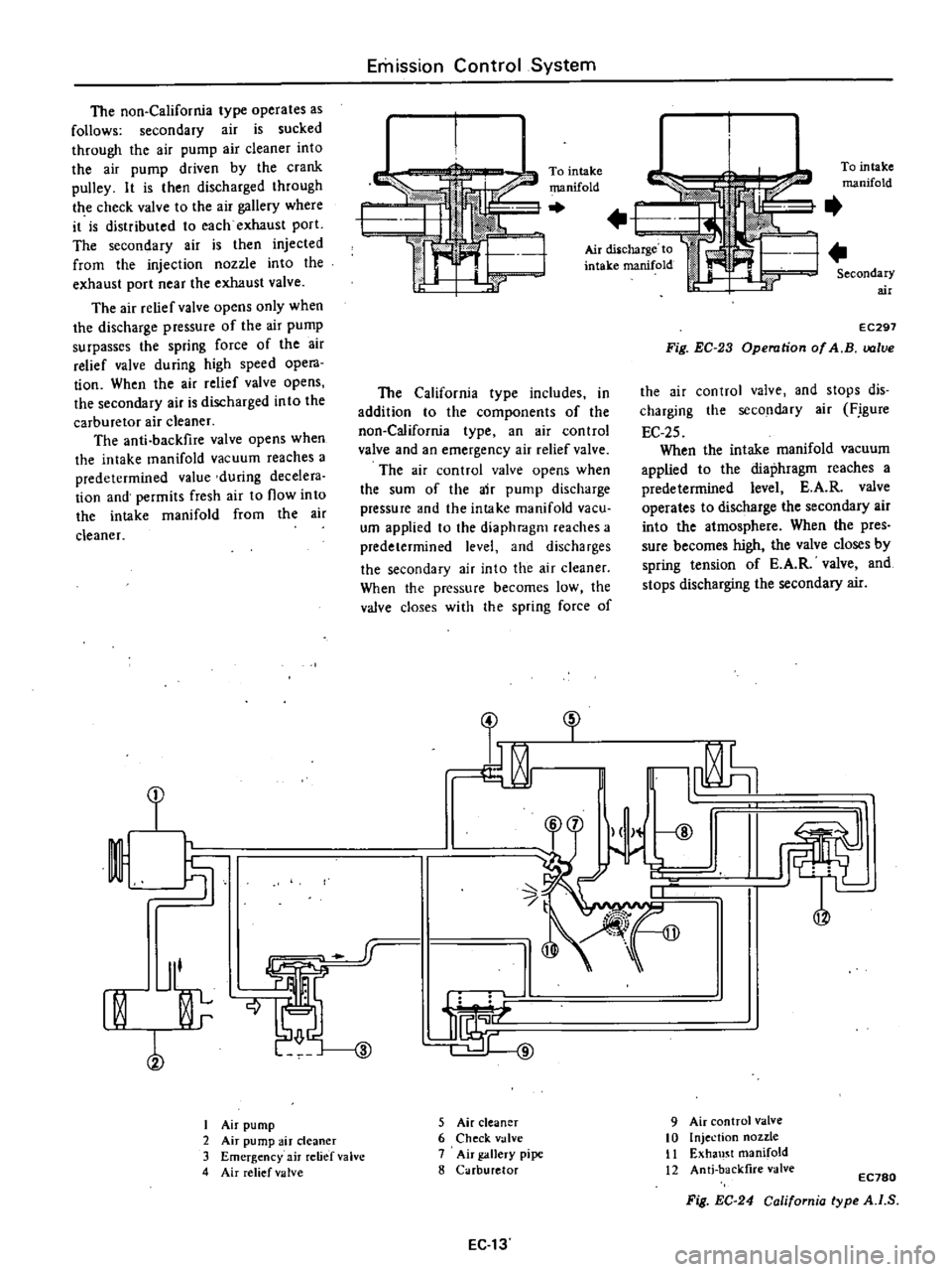
The
non
California
type
operates
as
follows
secondary
air
is
sucked
through
the
air
pump
air
cleaner
into
the
air
pump
driven
by
the
crank
pulley
It
is
then
discharged
through
the
check
valve
to
the
air
gallety
where
it
is
distributed
to
each
exhaust
porL
The
secondary
air
is
then
injected
from
the
injection
nozzle
into
the
exhaust
port
near
the
exhaust
valve
The
air
relief
valve
opens
only
when
the
discharge
pressure
of
the
air
pump
surpasses
the
spring
force
of
the
air
relief
valve
during
high
speed
opera
tion
When
the
air
relief
valve
opens
the
secondary
air
is
discharged
in
to
the
carburetor
air
c1eaner
The
anti
backfire
valve
opens
when
the
intake
manifold
vacuum
reaches
a
predetermined
value
during
decelera
tion
and
permits
fresh
air
to
now
into
the
intake
manifold
from
the
air
cleaner
f
I
Jl
rn
l
I
Air
pump
2
Air
pump
air
cleaner
3
Emergency
air
relief
valve
4
Air
relief
valve
riu
Qj
j
I
@
Emission
Control
System
To
intake
manifold
The
California
type
includes
in
addition
to
the
components
of
the
non
California
type
an
air
control
valve
and
an
emergency
air
relief
valve
The
air
control
valve
opens
when
the
sum
of
the
air
pump
discharge
pressure
and
the
intake
manifold
vacu
um
applied
to
the
diaphmgm
reaches
a
predetermined
level
and
discharges
the
secondary
air
into
the
air
cleaner
When
the
pressure
becomes
low
the
valve
doses
with
the
spring
force
of
3
5
Air
cleaner
6
Check
valve
7
Air
gallery
pipe
8
Carburetor
EC
13
To
intake
manifold
Air
diSlcharge
to
intake
manifold
Secondary
air
EC297
Fig
EC
23
Operation
of
A
B
lve
the
air
control
valve
and
stops
dis
charging
the
secondary
air
F
igure
EC
25
When
the
intake
manifold
vacuum
applied
to
the
diaphragm
reaches
a
predetermined
level
E
A
R
valve
operates
to
discharge
the
secondary
air
into
the
atmosphere
When
the
pres
sure
becomes
high
the
valve
closes
by
spring
tension
of
E
A
R
valve
and
stops
discharging
the
secondary
air
fl
t
9
Air
control
valve
10
Injection
nozzle
II
Exha
l
t
manifold
12
Anti
backfire
valve
EC780
Fig
EC
24
California
type
A
I
S
Page 168 of 537
DATSUN
PICK
UP
MODEL
620
SERIES
I
NISSAN
I
NISSAN
MOTOR
CO
LTD
TOKYO
JAPAN
SECTION
EE
ENGINE
ELECTRICAL
SYSTEM
BATTERY
EE
2
STARTING
MOTOR
EE
4
CHARGING
CIRCUIT
EE
12
ALTERNATOR
EE
15
REGULATOR
EE
20
IGNITION
CIRCUIT
EE
26
DISTRIBUTOR
EE
30
Non
California
models
DISTRIBUTOR
California
models
EE
33
TRANSISTOR
IGNITION
UNIT
California
models
IGNITION
COIL
SPARK
PLUG
EE
36
EE
46
EE
47
Page 169 of 537

REMOVAL
CHECKING
ELECTROLYTE
LEVEL
CHECKING
SPECIFIC
GRAVITY
REMOVAL
I
Disconnect
negative
and
positive
cables
2
Remove
nuts
from
battery
clamps
take
off
clamps
3
Remove
battery
CHECKING
ELECTROLYTE
LEVEL
Remove
six
vent
plugs
and
check
for
electrolyte
level
in
each
cell
If
nccessaJ
pour
distilled
water
CHECKING
SPECIFIC
GRAVITY
Specific
gravity
of
battery
electro
lyte
is
tested
by
a
hydrometer
If
the
srate
of
charge
of
battery
is
60
or
specific
gravity
reading
is
below
1
20
as
corrected
at
200e
680F
bat
tery
must
be
recharged
or
battery
electrolyte
concentration
adjusted
Add
or
subtract
gravity
points
according
to
whether
the
electrolyte
temperature
is
above
or
below
200e
680F
standard
The
gravity
of
electrolyte
chlll
ges
0
0007
for
every
Ioe
1
80F
tem
petature
A
correction
can
then
be
made
by
using
the
following
formula
Engine
Electrical
System
BATTERY
CONTENTS
EE
2
EE
2
EE
2
BATTERY
FREEZING
CHARGING
INST
ALLA
TION
S
20
St
0
0007
t
20
Where
St
Specific
gravity
of
electrolyte
at
tOe
520
Specific
gravity
of
electrolyte
corrected
at
200e
680F
t
Electrolyte
temperature
For
example
A
hydrometer
reading
of
1
260
at
300e
860F
would
be
1
267
corrected
to
200e
6goF
indicating
fully
charged
battery
On
the
other
hand
a
hydro
meter
reading
of
1
220
at
lOoe
140
F
would
be
1
199
corrected
to
200e
680F
indicating
a
partially
charged
battery
The
state
of
charge
of
battery
can
be
determined
by
the
following
table
if
the
specific
gravity
of
electrolyte
is
known
BefOIe
checking
be
sure
that
cells
are
filled
to
correct
level
G
U
o
N
b
t
E
u
ol
1
lilt
I
i
I
m
J
I
I
I
I
J
1
I
J
Sf
to
7
1
II
It
100
0wJIztI
COJJditioD
EE002
Fig
EE
2
ChaJ
ffing
condition
EE
2
1
28
@
126
S
Sow
E
l
l
u
o
o
l
e
u
0
U21
1
101
EE
3
EE
3
EE
3
Read
top
level
with
scale
1
Thermal
gauge
2
Hydrometer
feOOl
Fig
EE
l
Checking
pccme
gravity
Converted
specific
gavity
20
1
Je
I
dOldlOiJ
OSQ
Electrolyte
temperature
oC
EEOO3
Fig
EE
3
Specific
lNWity
at
eiectroly
te
temperature
Page 170 of 537

BATTERY
FREEZING
Battery
electrolyte
freezing
point
varies
with
acid
concentration
or
its
specific
gravity
A
battery
with
an
insufficient
charge
will
freeze
at
lower
temperatures
If
specific
gravity
of
a
battery
falls
below
1
1
this
is
an
0
10
20
30
g
40
I
u
il
SO
I
0
e
60
0
E
70
Engine
Electrical
System
indication
that
battery
is
completely
discharged
and
will
freeze
readily
when
temperatures
fall
below
freezing
Note
Use
extreme
caution
to
avoid
freezing
battery
since
freezing
will
generally
ruin
the
battery
1
80
1
00
1
04
1
08
t
l2
1
16
t
20
1
24
1
28
Specific
gravity
of
electrolyte
CHARGING
I
f
electrolyte
level
is
satisfactory
battery
must
be
charged
when
electro
lyte
gravity
reading
falls
below
1
20
If
battery
on
car
is
quick
charged
to
1
32
EEOQ4
Fig
EE
4
Froezing
point
of
electrolyte
bring
it
up
to
full
charge
the
opera
tion
should
be
carried
out
with
nega
tive
cable
removed
Prior
to
charging
corroded
termi
EE
3
nals
should
be
cleaned
with
a
brush
and
common
baking
soda
solution
In
addition
the
following
items
should
be
observed
while
battery
is
being
charged
I
Be
sure
that
electrolyte
level
is
above
top
of
each
plate
2
Keep
removed
plugs
in
a
safe
place
3
Do
not
allow
electrolyte
tempera
ture
to
go
over
450C
I130F
4
After
charging
check
to
be
cer
tain
that
specific
gravity
does
not
exceed
1
260
at
200C
680P
Cor
rection
can
be
made
by
adding
dis
tilled
water
into
cells
as
necessary
5
Keep
battery
away
from
open
flame
while
it
is
being
charged
6
After
all
vent
plugs
have
been
tightened
clean
all
sprayed
electrolyte
off
upper
face
of
battery
INSTALLATION
1
Install
and
tighten
clamps
secure
Iy
2
After
clamps
have
been
tightened
clean
battery
cable
terminals
and
apply
grease
to
retard
formation
of
corrosion
Page 179 of 537
Condition
Engine
Electrical
System
Probable
cause
Starting
motor
cranks
slowly
Dirty
or
worn
commutator
Armature
rubs
field
coil
Damaged
solenoid
switch
Starting
motor
operates
but
does
not
crank
engine
Worn
pinion
Locked
pinion
guide
Worn
ring
gear
Starting
motor
will
not
disengage
even
if
ignition
switch
is
turned
off
Damaged
solenoid
switch
Damaged
gear
teeth
The
charging
circuit
consists
of
the
battery
alternator
regulator
and
necessary
wiring
to
connect
these
parts
The
purpose
of
this
system
is
to
convert
mechanical
energy
from
the
engine
into
electrical
energy
which
is
used
to
operate
all
electrically
operat
ed
units
and
to
keep
the
battery
fully
charged
When
the
ignition
switch
is
set
to
ON
current
flows
from
the
battery
to
ground
through
the
ignition
switch
voltage
regulator
IG
terminal
primary
side
contact
point
PI
movable
contact
point
P2
voltage
regulator
IF
terminal
alternator
IF
terminal
rotor
field
coil
and
alternator
E
terminal
as
shown
in
Figure
EE
23
by
full
line
arrow
marks
Then
the
rotor
in
the
alternator
is
excited
On
the
other
hand
current
flows
from
the
battery
to
ground
through
the
ignition
switch
warning
lamp
voltage
regula
tor
L
terminal
lamp
side
contact
point
P4
movable
contact
point
P5
and
voltage
regulator
E
termi
nal
as
shown
by
dotted
line
arrow
CHARGING
CIRCUIT
marks
Then
the
warning
lamp
lights
When
the
alternator
begins
to
op
erate
three
phase
alternating
current
is
induced
in
the
stator
armature
coil
This
alternating
current
is
rectified
by
the
positive
and
negative
silicon
diodes
The
rectified
direct
current
output
reaches
the
alternator
A
and
E
terminals
On
the
other
hand
the
neutral
point
voltage
reaches
N
and
E
terminals
nearly
a
half
of
the
output
voltage
and
current
flows
from
voltage
regulator
N
terminal
to
E
terminal
or
ground
through
the
coil
VCI
as
shown
in
Figure
EE
24
by
the
dotted
line
arrow
marks
Then
the
coil
VCI
is
excited
and
the
movable
contact
point
IPS
comes
into
contact
with
voltage
winding
side
contact
point
P6
This
action
causes
to
turn
off
the
warning
lamp
and
complete
the
voltage
winding
circuit
as
shown
by
the
full
line
arrow
marks
When
the
alternator
speed
is
in
creased
or
the
voltage
starts
to
rise
excessively
the
movable
contact
point
EE
12
Corrective
action
Clean
and
repair
Replace
assembly
Repair
or
replace
Replace
Repair
Replace
Repair
or
replace
Replace
damaged
gear
P2
is
separated
from
the
primary
side
contact
PI
by
the
magnetic
force
of
coil
VC2
Therefore
registor
RI
is
applied
into
the
rotor
circuit
and
output
voltage
is
decreased
AJ
the
output
voltage
is
decreased
the
movable
contact
point
P2
and
primary
side
contact
Pin
comes
into
contact
once
again
and
the
alternator
voltage
increases
Thus
the
rapid
vibration
of
the
movable
contact
point
IPl
maintains
an
alternator
output
voltage
constant
When
the
alternator
speed
is
further
increased
or
the
voltage
starts
to
rise
excessively
the
movable
contact
point
P2
comes
into
contact
with
secondllJ
side
contact
point
P3
Then
the
rotor
current
is
shut
off
and
alternator
output
voltage
is
decreased
immediately
This
action
causes
movable
contact
n
to
separate
from
secondary
contact
P3
Thus
the
rapid
vibration
of
the
movable
contact
point
P2
or
breaking
and
completing
the
rotor
circuit
maintains
an
alternator
output
voltage
constant
Page 180 of 537
Engine
Electrical
System
r
l
I
I
I
i
r
Ye
Ff
p
Stator
ma
ture
coiJ
FF
vw
I
I
RI
L
Rot
r
field
C
oil
e
R
I
I
I
I
I
J
1
J
Alternator
Voltage
regulator
11
t
c
I
Fusible
link
t
8
c
J
5
9
i
c
c
0
Battery
t
u
J
EE029
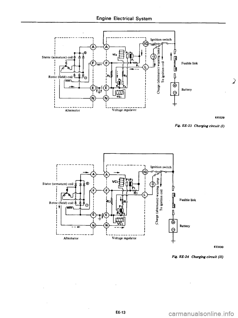
Fig
EE
23
Charging
circuit
II
p
ns
1
Slator
ar
ature
coil
teJ
U
2iI
I
r
R
l
I
I
A3
R2
0
Fusible
link
Roto
field
coil
e
I
I
t
I
I
PS
M
g
j
t
i
H
U
Battery
Lh
A
l
a
o
J
L
V
It
g
t
f
EE030
Fig
EE
24
Charging
circuit
II
EE
13
Page 181 of 537
Engine
Electrical
System
B
v
W
WR
WL
L2
VOLTAGE
REGULATOR
co
LW
I
P
B
r
FUSIBLE
LINK
m
I
WLI
LW
cJ
I
B
t
EARTH
POINT
m
WR
WR
CHARGE
g
00
WARNING
lAMP
00000
Equipped
with
cooler
I
I
I
I
TjT
m
CLB
W
WB
B
YWR
I
I
I
I
1
W
B
rn
ALTERNATOR
I
l
LW
BW
j
J
M
IG
I
W
BwtIl
IGNITION
SWITCH
COLOR
CODE
B
Black
OW
Black
with
white
stripe
W
White
WB
White
with
black
stripe
WR
White
with
red
stripe
WL
White
with
blue
stripe
LO
Blue
with
black
stripe
LW
Blue
with
white
stripe
Y
Yellow
lOA
C
o
0
0
0
o
0
0
FUSE
BLOCK
M
0
0
0
lOA
Ii
California
models
E
E492
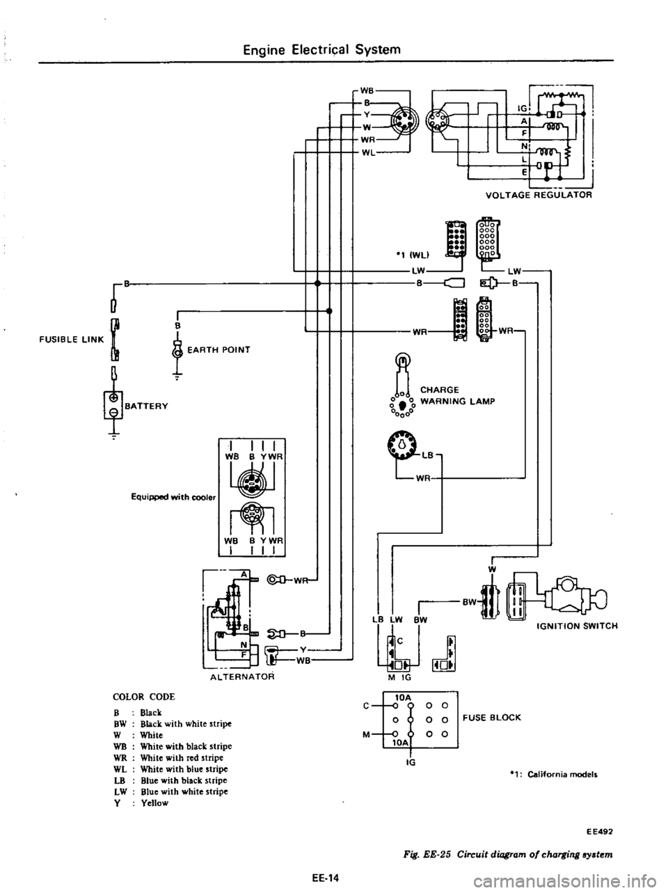
Fig
EE
25
Circuit
diagram
of
charging
lfY
t
m
EE
14
Page 182 of 537
DESCRIPTION
REMOVAL
DISASSEMBLY
INSPECTION
AND
REPAIR
ROTOR
INSPECTION
INSPECTION
OF
STATOR
DESCRIPTION
In
the
alternator
a
magnetic
field
is
produced
by
the
rotor
which
consists
of
alternator
shaft
field
coil
pole
pieces
and
slip
rings
The
slip
rings
pressed
in
the
shaft
conduct
only
a
small
field
current
Output
current
is
generated
in
the
armature
coils
located
in
the
stator
The
stator
has
three
windings
and
generates
three
phase
alternating
current
Silicon
diodes
act
@God
A
tfff
Engine
Electrical
System
ALTERNATOR
CONTENTS
EE
15
EE
16
EE
16
EE
16
EE
17
EE
17
INSPECTION
OF
DIODE
INSPECTION
OF
BRUSH
SPRING
PRESSURE
TEST
ASSEMBL
Y
ALTERNATOR
TEST
SERVICE
DATA
AND
SPECIFICATIONS
EE
17
EE
1B
EE1B
EE
1B
EE19
EE
19
like
a
one
way
valve
for
electricity
so
that
charging
current
passes
easily
but
reverse
current
is
shut
out
In
this
alternator
pack
type
silicon
di
odes
are
used
Six
diodes
three
negative
and
three
positive
are
installed
in
positive
and
negative
plates
as
an
assembly
These
diodes
are
direct
soldered
at
their
tips
and
constructed
with
posi
3
2
I
4
e
o
e
9
tive
and
negative
conjunction
They
are
mounted
on
the
two
plates
which
combine
the
function
of
heat
dissipating
plate
and
positive
negative
terminals
and
are
light
in
weight
and
easy
to
service
The
pulley
mounted
on
the
air
conditioner
models
is
different
from
that
on
the
standard
models
without
air
conditioner
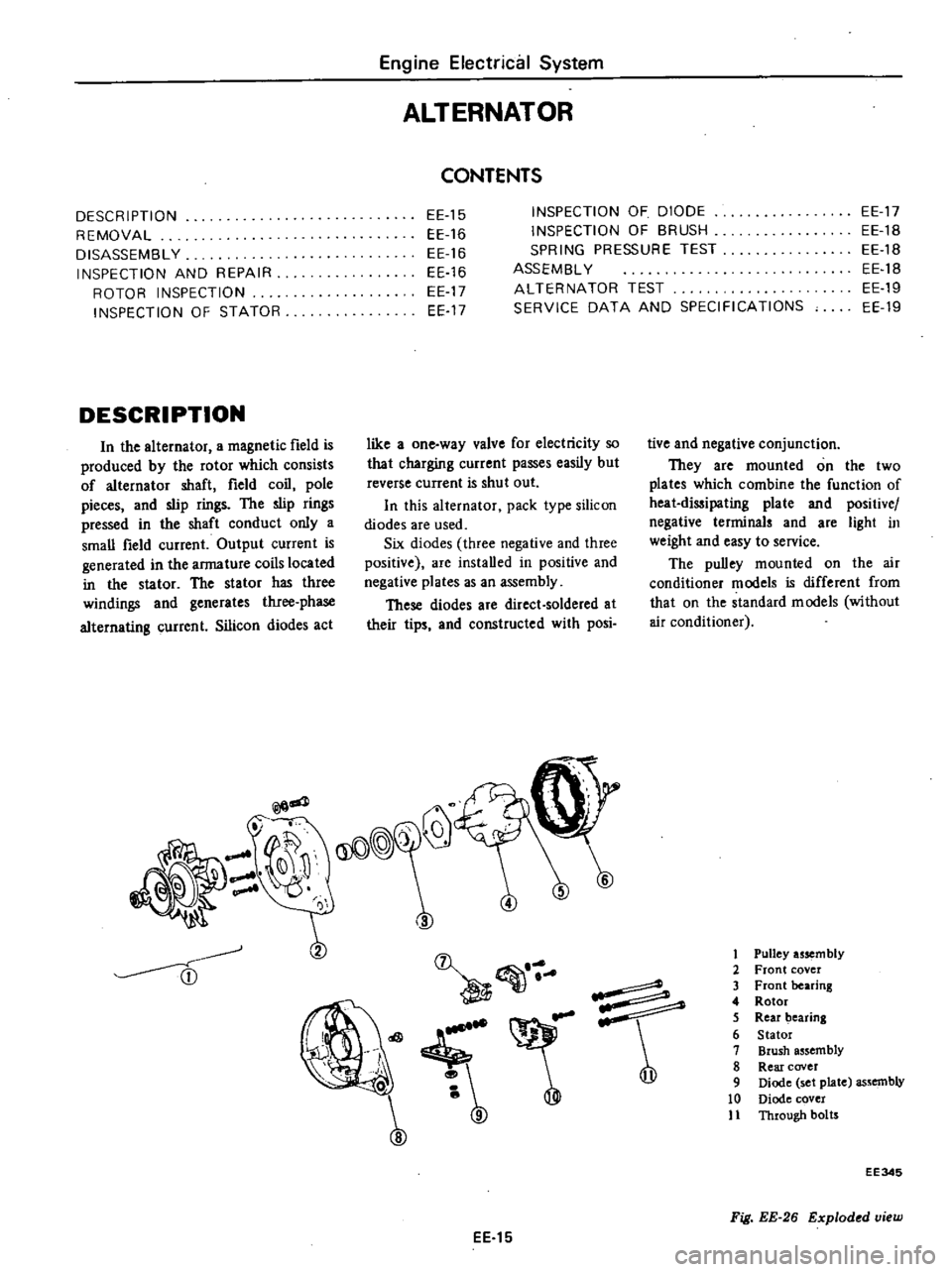
1
Pulley
usem
bly
2
Front
cover
3
Front
bearing
4
Rotor
5
Rear
bearing
6
Stator
7
Brush
assembly
8
Rear
cover
9
Diode
set
plate
assembly
10
Diode
cover
11
Through
botrs
EE
15
EE345
Fig
EE
26
Exploded
view
Page 187 of 537

DESCRIPTION
MEASUREMENT
OF
REGULATOR
VOLTAGE
ADJUSTMENT
VOLTAGE
REGULATOR
DESCRIPTION
The
regulator
consists
basically
of
a
voltage
regulator
and
a
charge
relay
The
voltage
regulator
has
two
sets
of
contact
points
a
lower
set
and
an
upper
set
to
control
alternator
volt
age
An
armature
plate
placed
between
the
two
sets
of
contacts
moves
upward
or
downward
or
vibrates
The
lower
contacts
when
closed
complete
the
jCV
ID@
@
GJ
I
@
@
@
Engine
Electrical
System
REGULATOR
CONTENTS
EE
20
CHARGING
RELAY
SERVICE
DATA
AND
SPECIFICATIONS
TROUBLE
DIAGNOSES
AND
CORRECTIONS
Including
alternatorl
EE
25
EE
23
EE
24
EE
20
EE
23
EE
23
field
circuit
direct
to
ground
and
the
upper
contacts
when
closed
complete
the
field
circuit
to
ground
through
a
resistance
field
coil
and
produce
alternator
output
The
charge
relay
i
similar
in
construction
to
the
voltage
regulator
When
the
upper
contacts
are
closed
charge
warning
lamp
goes
on
v
1
Charge
relay
2
Voltage
regulator
EE285
Fig
EE
46
View
of
removing
cover
As
regards
the
construction
the
voltage
regulator
is
very
similar
to
the
charge
relay
as
shown
in
Figure
EE47
@
r
J
CD
@
@
@
Q
@
ID@
ID@
J
t
L
T
@
r
b
r
CD
L
@
j
1
g
f
@
@
EEJ97
J
I1Jlccting
spring
2
Y
kt
g
p
3
Armaturc
4
Core
go
5
Low
Sllccd
lnlacl
h
Point
ap
7
High
speed
conlat
t
8
Contact
c
9
3111111
0
118
ill
di
10
41l1I11W
157in
c1ia
few
II
Cuil
12
lock
nut
J3
Adjllslin
screw
14
Adjll
sting
sprin
15
Yoke
9
Adjusting
screw
10
Lock
nut
11
Coil
12
4mm
0
157
in
dia
screw
13
3mm
0
118
in
dla
crew
14
Contact
iet
15
Voltage
cgulatm
contact
a
Cnl1
Tlll
tion
f
lltagl
l
j
llIOltllT
I
Point
gilp
2
Charge
relay
contllct
3
Core
gap
4
ArlllatlJre
5
Connecting
sprin
6
Yoke
gap
7
Yoh
B
Adjusting
pring
b
Construction
of
charge
relay
Fig
EE
47
Structural
vi
w
EE
20
Page 191 of 537

Engine
Electrical
System
RegulatoI
r
Yellow
terminal
A
W
L
WR
IG
WL
N
Y
E
B
F
WB
Voltmeter
Fig
EE
52
Tuting
charging
re
Qy
EE348
SERVICE
DATA
AND
SPECIFICATIONS
Voltage
legulator
Type
Regulating
voltage
with
fully
charged
battery
Voltage
coil
resistance
RotOI
coil
inserting
resistance
Voltage
coil
series
resistance
Smoothing
resistance
COle
gap
Point
gap
Ch
uge
lay
Release
voltage
Voltage
coil
resistance
Core
gap
Point
gap
v
fl
nun
in
nun
in
V
fl
nun
in
mID
in
TLl
Z
S5C
14
3
to
15
3
at
200C
680F
10
5
at
200C
680F
10
31
40
0
6
to
1
0
0
024
to
0
039
0
35
to
0
45
0
014
to
O
OIS
4
2
to
5
2
at
N
terminal
37
S
at
200C
680F
0
8
to
1
0
0
031
to
0
039
0
4
to
0
6
0
016
to
0
024
Standard
tempelatUIe
gIlIdient
O
OISV
oC
EE
24