charging DATSUN PICK-UP 1977 User Guide
[x] Cancel search | Manufacturer: DATSUN, Model Year: 1977, Model line: PICK-UP, Model: DATSUN PICK-UP 1977Pages: 537, PDF Size: 35.48 MB
Page 297 of 537
Automatic
Transmission
REMOVAL
AND
INSTALLATION
TRANSMISSION
ASSEMBLY
REMOVAL
INSTALLATION
TRANSMISSION
ASSEMBLY
When
dismounting
the
automatic
transmission
from
a
vehicle
pay
at
tention
to
the
following
points
1
Before
dismounting
the
trans
mission
rigidly
inspecl
it
by
aid
of
the
Troubleshooting
Chart
and
dis
mount
it
only
when
considered
to
be
necessary
2
Dismount
the
transmission
with
utmost
care
and
when
mounting
observe
the
tightening
torque
indi
cated
on
another
table
not
to
exert
excessive
force
REMOVAL
In
dismounting
automatic
transmis
sion
from
vehicle
proceed
as
follows
I
Disconnect
battery
ground
cable
from
terminal
2
Disengage
torsion
shaft
from
ac
celerator
linkage
3
Jack
up
vehicle
and
support
its
weight
on
safety
stands
Recommend
a
hydraulic
hoist
or
open
pit
be
utilized
if
available
Make
sure
that
safety
is
insured
4
Remove
propeller
shaft
Note
Plug
up
the
opening
in
the
rear
extension
to
prevent
oil
from
flowing
out
5
Disconnect
front
exhaust
tube
6
Disconnect
selector
range
lever
from
manual
shaft
7
Disconnect
wire
connections
at
inhibitor
switch
CONTENTS
AT
33
AT
33
AT
33
TRANSMISSION
CONTROL
LINKAGE
REMOVAL
AND
INSTALLATION
ADJUSTMENT
AT
35
AT
35
AT
35
8
Disconnect
vacuum
tube
from
vacuum
diaphragm
and
wire
connee
lions
at
downshift
solenoid
9
Disconnect
speedometer
cable
from
rear
extension
10
Disconnect
oil
charging
pipe
II
Disconnect
oil
cooler
inlet
and
outlet
tubes
at
transmission
case
12
Support
engine
by
locating
a
jack
under
oil
pan
with
a
wooden
block
used
between
oil
pan
and
jack
Support
transmission
by
means
of
a
transmission
jack
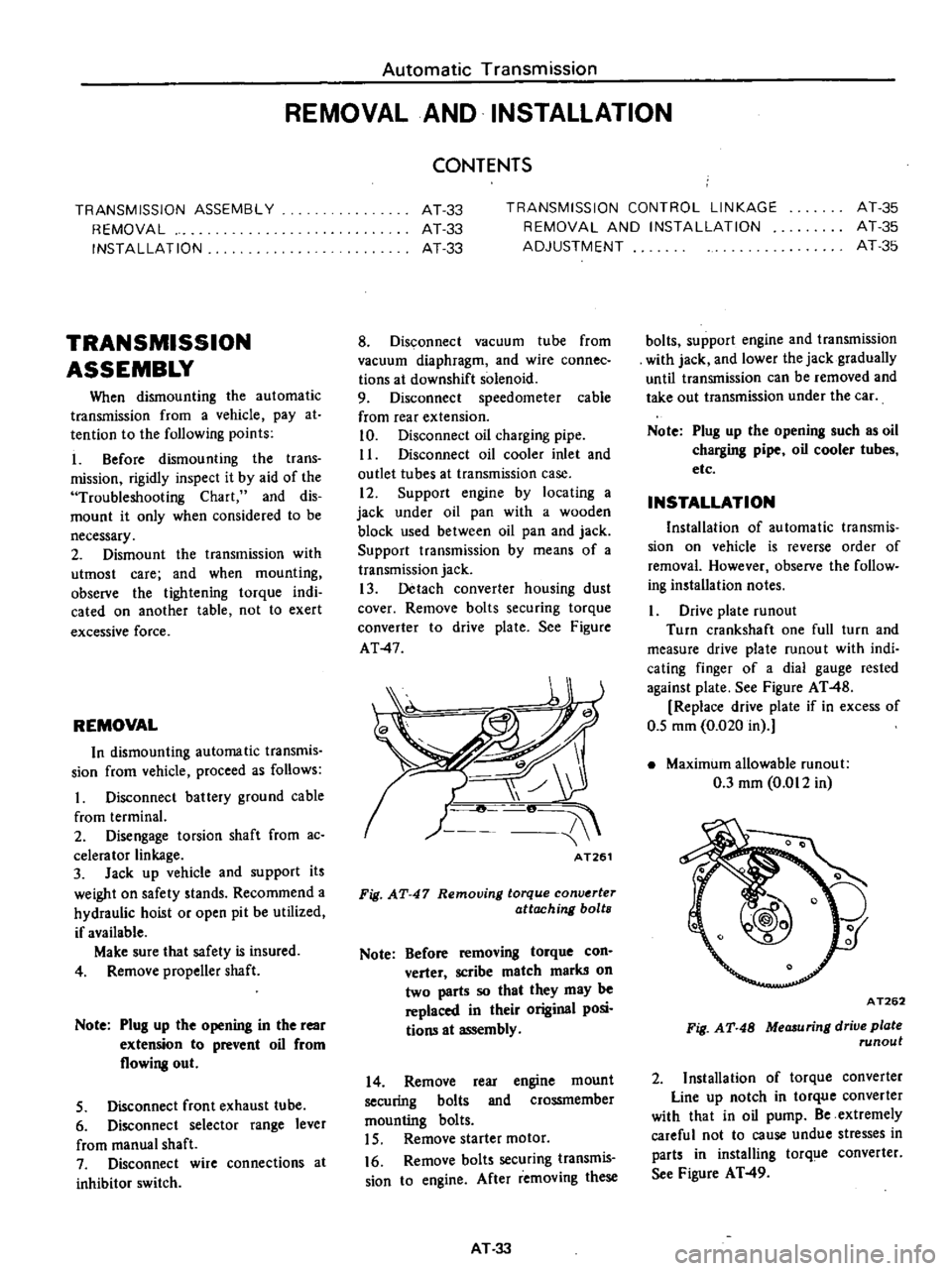
13
Detach
converter
housing
dust
cover
Remove
bolts
securing
torque
converter
to
drive
plate
See
Figure
AT
4
AT261
Fig
AT
47
Removing
torque
conv
rter
attaching
bolts
Note
Before
removing
torque
con
verter
scribe
match
marks
on
two
parts
so
that
they
may
be
replaced
in
their
original
posi
tions
at
assembly
14
Remove
rear
engine
mount
securing
bolts
and
crossmember
mounting
bolts
15
Remove
starter
motor
16
Remove
bolts
securing
transmis
sion
to
engine
After
removing
these
AT
33
bolts
support
engine
and
transmission
with
jack
and
lower
the
jack
gradually
until
transmission
can
be
removed
and
take
out
transmission
under
the
car
Note
Plug
up
the
opening
such
as
oil
charging
pipe
oil
cooler
tubes
etc
INSTALLATION
Installation
of
automatic
transmis
sion
on
vehicle
is
reverse
order
of
removal
However
observe
the
follow
ing
installation
notes
Drive
plate
runout
Turn
crankshaft
one
full
turn
and
measure
drive
plate
mnou
t
with
indi
cating
finger
of
a
dial
gauge
rested
against
plate
See
Figure
AT
48
Replace
drive
plate
if
in
excess
of
0
5
mm
0
020
in
Maximum
allowable
mnout
0
3
mm
0
012
in
A
T262
Fig
AT
48
MeCJ
uring
drive
plate
runout
2
Installation
of
torque
converter
Line
up
notch
in
torque
converter
with
that
in
oil
pump
Be
extremely
careful
not
to
cause
undue
stresses
in
parts
in
installing
torq
e
converter
See
Figure
AT
49
Page 313 of 537
In
these
cases
the
transmission
must
be
repaired
Notes
a
In
checking
oil
level
use
special
paper
cloth
to
handle
the
level
gauge
and
be
careful
not
to
let
the
scraps
of
paper
and
cloth
stick
to
the
gauge
b
Insert
the
gauge
fully
and
take
it
out
quickly
before
splashing
oil
adheres
to
the
gauge
Then
observe
the
level
c
Use
automatic
transmission
fluid
having
DEXRON
identifications
only
in
the
3N71B
automatic
trans
mission
d
Pay
attention
because
the
oil
to
be
used
differs
from
that
used
in
the
Nissan
Full
Automatic
TranSJTIis
sion
3N71A
Never
mix
the
oils
INSPECTION
AND
REPAIR
OF
OIL
LEAKAGE
When
oil
leakage
takes
place
the
portion
near
the
leakage
is
covered
with
oil
presenting
difficulty
in
detecting
the
spot
Therefore
the
places
where
oil
seals
and
gaskets
are
equipped
are
enumerated
below
11
Converter
housing
Rubber
ring
of
oil
pump
housing
Oil
seal
of
oil
pump
housing
Oil
seal
of
engine
crankshaft
Bolts
of
converter
housing
to
case
2
Trarismission
and
rear
extension
Junction
of
transm
ss
ion
and
rear
extension
J
Oil
cooler
tube
connectors
Oil
pan
Oil
pressure
inspection
holes
Refer
to
Figure
AT
il2
Mounting
portion
of
vacuum
dia
phragm
and
downshift
solenoid
Breather
and
oil
charging
pipe
Speedometer
pinion
sleeve
Oil
se
l
of
rear
extension
To
exactly
locate
the
place
of
oil
leaka
le
proceed
as
follows
Place
the
vehicle
in
a
pit
and
by
sampling
the
leaked
oil
determine
if
it
is
the
torque
converter
oil
The
torque
converter
oil
has
a
color
like
r
d
wine
So
it
is
easily
distinguished
from
engine
oil
or
gear
oil
Automatic
rransmission
Wipe
off
the
leaking
oil
and
dust
and
deiecl
the
spol
of
oil
eakage
l
se
nonflammable
organic
solve
t
s
ch
as
carbon
tetrachloride
for
wiping
Raise
the
oil
tcmperalure
by
op
erating
the
engine
and
shift
the
lever
to
D
to
increase
the
oil
pressure
The
spot
of
oil
lcakage
will
then
be
found
more
easily
Note
As
oil
leakage
from
the
breaih
er
does
not
take
place
except
when
running
at
high
speed
it
is
impos
sible
to
locate
this
leakage
with
vehicle
stationary
CHECKING
ENGINE
IDLING
REVOLUTION
The
engine
idling
revolution
should
be
properly
adjusted
If
the
engine
revolution
is
too
low
the
engine
does
not
operate
smoothly
and
if
too
high
a
strong
shock
or
creep
develops
when
changing
over
from
N
to
D
or
R
CHECKING
AND
ADJUSTING
KICK
DOWN
SWITCH
AND
DOWNSHIFT
SOLENOID
When
the
kickdown
operation
is
not
made
properly
or
the
speed
chang
ing
point
s
too
high
check
the
kick
down
switch
downshift
solenoid
and
wiring
between
them
When
the
igni
li
n
key
is
pqsitioned
a
t
the
I
st
stage
nd
the
accelerator
pedal
is
depressed
deeply
the
switch
contact
should
be
closed
and
the
solenoid
should
click
If
it
does
not
click
it
indicates
a
defect
Then
check
each
part
with
the
testing
instruments
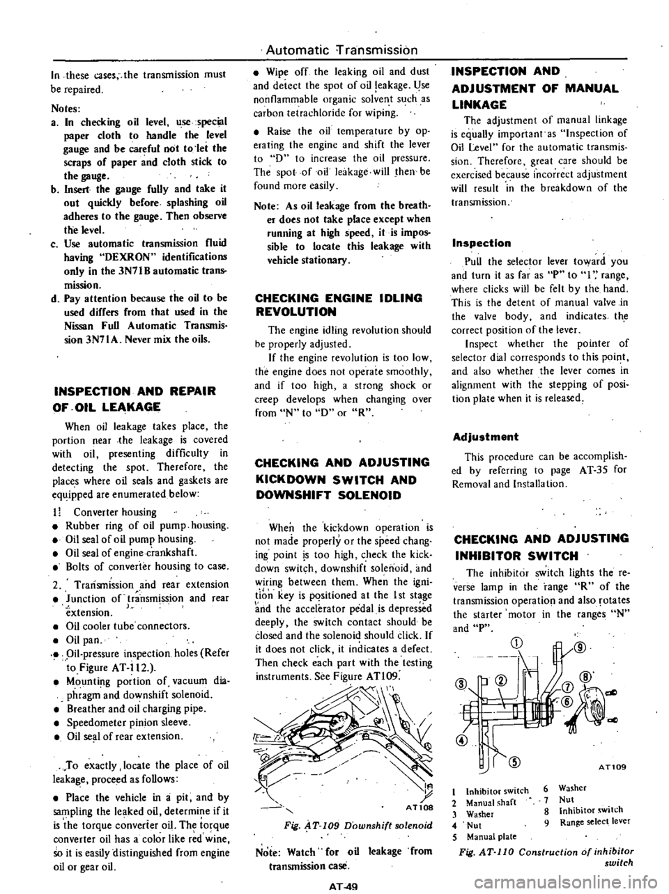
See
Figure
ATl09
d
I
t
AT10S
Fig
AT
109
Downshift
solenoid
Note
Watch
for
oil
leakage
from
transmission
case
AT
4Q
INSPECTION
AND
ADJUSTMENT
OF
MANUAL
LINKAGE
The
adjustmcnt
of
manual
linkage
is
equaUy
important
as
Inspection
of
Oil
Level
for
the
automatic
transmis
sion
Thereforc
great
care
should
be
exercised
because
incorrect
adjustment
will
rcsult
in
the
brcakdown
of
the
transmission
Inspection
Pull
the
selector
lever
toward
you
and
turn
it
as
far
as
P
to
I
range
wherc
clicks
will
be
felt
by
the
hand
This
is
the
detcnt
of
manual
valve
in
the
valve
body
and
indicates
th
correct
position
of
the
lever
Inspect
whether
the
pointer
of
selector
dial
corresponds
to
this
point
and
also
whether
the
lever
comes
in
alignment
with
the
stepping
of
posi
tion
plate
when
it
is
released
Adjustment
This
procedure
can
be
accomplish
ed
by
refcrring
to
page
AT
35
for
Removal
and
Installa
tion
CHECKING
AND
ADJUSTING
INHIBITOR
SWITCH
The
inhibitor
switch
lights
the
re
verse
lamp
in
the
range
R
of
the
transmission
operatio
l
and
also
rotates
the
starter
motor
in
the
ranges
N
and
P
CD
@
b
ell
If
L
t
7
4l
@
1l
j7
@
@
@
dl
AT109
6
Washer
7
Nut
8
Inhibitor
switch
9
Range
select
lever
t
Inhibitor
switch
2
Manual
shaft
3
Washer
4
Nut
5
Manual
plate
Fig
AT
110
Construction
of
inhibitor
switch
Page 320 of 537
Trouble
No
shock
at
change
from
I
to
2
range
or
engine
races
extremely
Failure
to
change
from
3rd
to
2nd
when
shifting
lever
into
I
range
Engine
brake
does
not
upcrate
in
1
range
Gear
change
frum
I
sr
lu
2nd
or
from
2nd
to
3rd
in
I
range
Does
not
change
f
rom
2nd
to
1st
in
range
Large
shock
changing
from
2nd
to
1st
in
range
Vehicle
moves
when
changing
into
P
range
or
parking
gear
does
not
disengage
when
shifted
out
of
P
range
Transmissic
m
overheats
Oil
shoots
out
during
operation
White
smoke
emitted
from
exhaust
pipe
during
operation
Offensive
smell
at
oil
charging
pipe
Transmission
noise
in
p
and
N
ranges
Transmission
noise
in
D
2
I
and
R
ranges
Automatic
Transmission
ABeD
E
F
G
H
I
J
K
L
1M
NO
P
1m
n
q
r
s
t
u
v
Iw
x
y
6
7
5
@
@
I
I
2
3
4
I
I
2
1
57
6
3
@@
@
I
2
4
5
3
@
f
1
2
@
1
2
4567
3
@
2
1
3
@
2
4
I
2
I
3
4
2
6
8
7
5
@@@
Q
@@
@
I
3
5
6
2
7
8
4
@@@
Q
@@
@
1
2
O
G
@@
f
@@
@
1
2
10
I
I
2
0
G
@
@
AT
56
Page 325 of 537
Automatic
Transmission
Engine
Idling
and
stall
revolution
Idling
revolution
Stall
revolution
rpm
rpm
6S0
ai
0
position
2
000
to
2
200
TIghtening
torque
kg
m
ft
lb
Drive
plate
to
crankshaft
Drive
plate
to
torque
converter
Converter
housing
to
engine
Transmission
case
to
converter
housing
Transmission
case
to
rear
extension
Oil
pan
to
transmission
case
Servo
piston
retaine
T
to
transmission
case
Pislon
slem
when
adjuting
band
brake
Piston
stem
lock
nut
One
way
clutch
inner
race
to
transmission
case
Control
valve
body
to
transmission
case
Lower
valve
body
to
upper
valve
body
Side
plat
to
control
valve
body
Nut
for
control
valve
reamer
bolt
Oil
strainer
to
lower
valve
body
Governor
valve
body
to
oil
distribu
tor
Oil
pump
housing
to
oil
pump
cover
Inhibitor
switch
to
transmission
case
Manual
shaft
lock
nut
Oil
cooler
pipe
to
transmission
case
Test
plug
oil
pressure
inspection
hole
Support
actuator
parking
rod
inserting
position
to
rear
extension
I
Oil
charging
pipe
to
case
Dust
cover
to
converter
housing
Selector
range
lever
to
manual
shaft
14
0
to
16
0
101
to
116
4
0
to
5
0
29
to
36
4
0
to
S
O
29
10
36
4
S
to
5
5
33
to
40
2
0
to
S
14
to
18
O
S
to
0
7
4
to
S
O
S
to
0
7
4
to
S
1
2
to
1
5
9
to
11
1
5
to
4
0
I
I
to
29
1
3
to
1
8
9
to
13
0
5S
to
0
75
4
to
S
0
25
to
O
3S
2
to
3
0
25
to
0
35
2
to
3
O
S
to
0
7
4
to
S
0
25
to
0
35
2
to
3
D
S
100
7
4
to
5
0
6
to
0
8
4
to
6
0
5
to
0
7
4
toS
3
0
to
4
0
22
to
29
3
0
to
S
O
22
to
36
I
4to
2
1
10
to
IS
0
8
to
I
1
6
to
8
O
5S
to
0
7S
4
to
S
O
5S
to
0
75
4
to
S
3
0
to
4
0
22
to
29
Turn
back
two
turns
after
tightening
AT
61
Page 447 of 537
DESCRIPTION
Cables
are
covered
with
color
coded
vinyl
for
easy
identification
In
the
wiring
diagram
colors
are
indicated
by
one
or
two
alphabetical
letters
It
is
recommended
that
the
battery
be
disconnected
before
performing
any
electrical
service
other
than
bulb
or
fuse
replacement
In
addition
to
fuses
a
fusible
link
has
been
installed
to
protect
wiring
The
fusible
link
functions
almost
the
same
as
a
fuse
though
its
eharac
teristics
are
slightly
different
than
normal
fuses
CABLE
COLORS
Cable
colors
are
indicated
by
one
or
two
alphabetical
letters
B
Black
Be
Brown
G
Green
L
Blue
Lg
Light
green
R
Red
W
White
Y
Yellow
The
main
cable
is
generally
coded
with
a
single
color
The
others
are
coded
with
a
two
tone
color
as
follows
BW
Black
with
white
stripe
gR
Light
green
with
red
stripe
INSPECTION
Inspect
all
electrical
circuits
refer
ring
to
wiring
or
circuit
diagrams
Circuits
should
be
tested
for
conti
nuity
or
short
circuit
with
a
conven
tional
test
lamp
or
low
reading
volt
meter
Before
inspection
of
circuit
ensure
that
I
Each
electrical
component
part
or
cable
is
securely
fastened
to
its
con
nector
or
terminal
2
Each
connection
is
firmly
in
place
and
free
from
rust
and
dirt
3
No
cable
covering
shows
any
evidence
of
cracks
deterioration
or
other
damage
4
Each
terminal
is
at
a
safe
distance
away
from
any
adjacent
metal
parts
5
Each
cable
is
fastened
to
its
proper
connector
or
terminal
Body
Electrical
System
BODY
ELECTRICAL
WIRING
6
Each
grounding
bolt
is
firmly
pbnted
7
Wiring
is
kept
away
from
any
adjacent
parts
with
sharp
edges
or
high
temperature
parts
such
as
exhaust
pipe
8
Wiring
is
kept
away
from
any
rotating
or
working
parts
fan
pulley
fan
belt
etc
9
Cables
between
ftxed
portions
and
moving
parts
are
long
enough
to
withstand
shocks
and
vibratory
forces
Notes
a
Before
starting
to
inspect
and
repair
any
part
of
electrical
system
or
other
parts
which
may
lead
to
a
short
circuit
disconnect
cables
at
battery
terminals
as
follows
Disconnect
cable
at
negative
terminal
and
then
disconnect
cable
at
positive
terminal
Before
connecting
cables
to
battery
terminal
be
sure
to
clean
terminals
with
a
rag
Fasten
cable
at
positive
terminal
and
then
ground
cable
at
negative
terminal
Apply
grease
to
top
of
these
terminals
to
prevent
rust
from
developing
on
them
b
Never
use
a
screwdriver
or
senrice
tool
to
conduct
a
continuity
test
Use
test
leads
c
Never
ground
an
open
circuit
or
circuits
under
no
load
Use
a
test
lamp
12V
3W
or
circuit
tester
as
a
load
FUSE
AND
FUSIBLE
LINK
DESCRIPTION
The
fuse
and
fusible
link
are
protec
tive
devices
used
in
an
electrical
cir
cuit
When
current
increases
beyond
rated
amperage
fusible
metal
melts
and
the
circuit
is
broken
BE
2
MAINTENANCE
INSTRUCTIONS
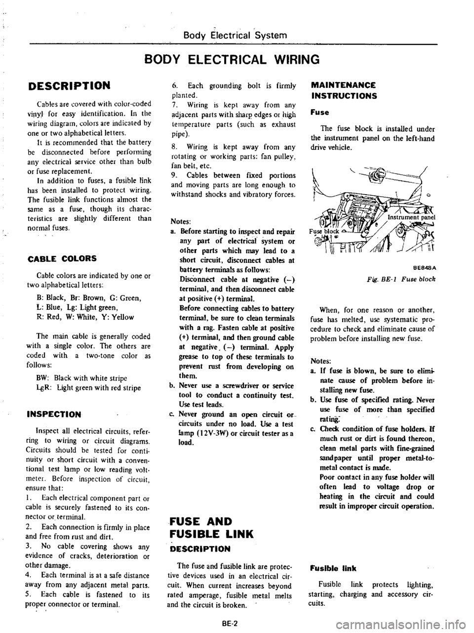
Fuse
The
fuse
block
is
installed
under
the
instrument
panel
on
the
left
hand
drive
vehicle
BE848A
Fig
BE
1
Fuse
block
When
for
one
reason
or
another
fuse
has
melted
use
systematic
pro
cedure
to
check
and
eliminate
cause
of
problem
before
installing
new
fuse
Notes
a
If
fuse
is
blown
be
sure
to
elimi
nate
cause
of
problem
before
in
stalling
new
fuse
b
Use
fuse
of
specified
rating
Never
use
fuse
of
more
than
specified
rating
Co
Check
condition
of
fuse
holders
If
much
rust
or
dirt
is
found
thereon
clean
metal
parts
with
fine
grained
sandpaper
until
proper
metal
to
metal
contact
is
made
Poor
contact
in
any
fuse
holder
will
often
lead
to
voltage
drop
or
heating
in
the
circuit
and
could
result
in
improper
circuit
operation
Fusible
link
Fusible
link
protects
lighting
starting
charging
and
accessory
cir
cuits
Page 458 of 537
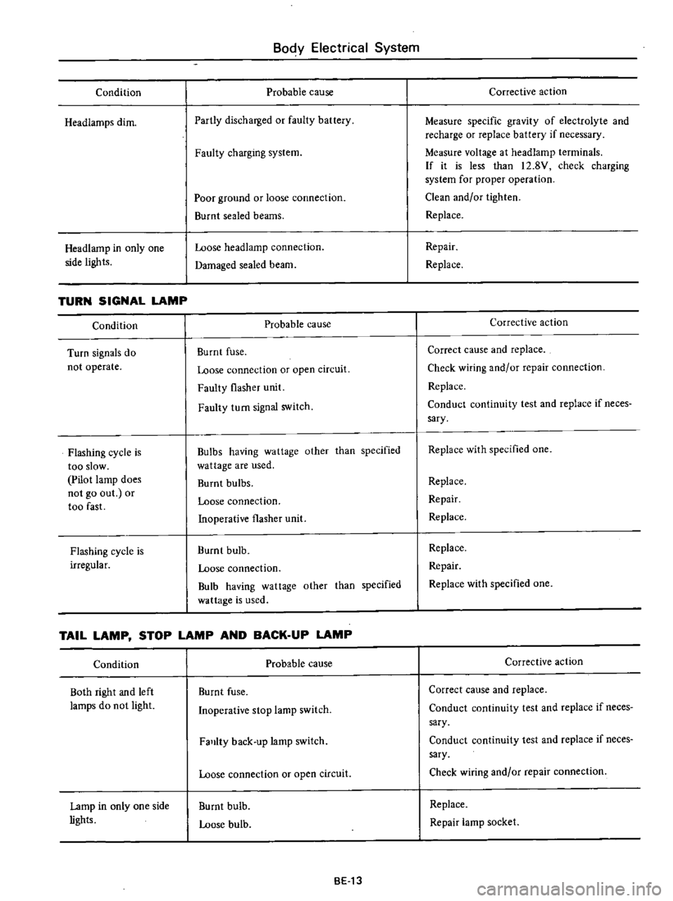
Condition
Headiamps
dim
Headlamp
in
only
one
side
lights
TURN
SIGNAL
LAMP
Condition
Turn
signals
do
not
operate
Flashing
cycle
is
too
slow
Pilot
lamp
does
not
go
out
or
too
fast
Flashing
cycle
is
irregular
Body
Electrical
System
Probable
cause
Partly
discharged
or
faulty
battery
Faulty
charging
system
Poor
ground
or
loose
connection
Burnt
sealed
beams
Loose
headlamp
connection
Damaged
sealed
beam
Probable
cause
Burnt
fuse
Loose
connection
or
open
circuit
Faulty
flasher
unit
Faulty
turn
signal
switch
Bulbs
having
wattage
other
than
specified
wattage
are
used
Burnt
bulbs
Loose
connection
Inoperative
flasher
unit
Burnt
bulb
Loose
connection
Bulb
having
wattage
other
than
specified
wa
ttage
is
used
TAIL
LAMP
STOP
LAMP
AND
BACK
UP
LAMP
Condition
Both
right
and
left
lamps
do
not
light
Lamp
in
only
one
side
lights
Probable
cause
Burnt
fuse
Inoperative
stop
lamp
switch
Falllty
back
up
lamp
switch
Loose
connection
or
open
circuit
Burnt
bulb
Loose
bulb
BE13
Corrective
action
Measure
specific
gravity
of
electrolyte
and
recharge
or
replace
battery
if
necessary
Measure
voltage
at
headlamp
terminals
If
it
is
less
than
12
8V
check
charging
system
for
proper
operation
Clean
and
or
tighten
Replace
Repair
Replace
Corrective
action
Correct
cause
and
replace
Check
wiring
and
or
repair
connection
Replace
Conduct
continuity
test
and
replace
if
neces
sary
Replace
with
specified
one
Replace
Repair
Replace
Replace
Repair
Replace
with
specified
one
Corrective
action
Correct
cause
and
replace
Conduct
continuity
test
and
replace
if
neces
sary
Conduct
continuity
test
and
replace
if
neces
sary
Check
wiring
and
or
repair
connection
Replace
Repair
lamp
socket
Page 465 of 537
Condition
Fuel
gauge
Fuel
gauge
does
not
operate
Pointer
indicates
only
F
position
Body
Electrical
System
Probable
cause
Faulty
tank
unit
or
loose
unit
terminal
connection
pointer
indicates
a
half
level
when
a
35U
resistance
is
connected
between
tank
unit
yellow
wire
and
ground
Faulty
fuel
gauge
Poor
or
loose
cormection
Open
circuit
Faulty
tank
unit
pointer
lowers
below
E
mark
when
igni
tion
switch
Is
turned
off
Faulty
fuel
gauge
pointer
still
indicates
F
position
when
ignition
switch
is
turned
off
OIL
P
RESSURE
AND
CHARGE
WARNING
LAMPS
Condition
Oil
pressure
wamiug
lamp
Lamp
does
not
light
when
ignition
switch
is
set
to
ON
Lamp
does
not
go
out
while
engine
is
being
operated
OIarge
warning
lamp
Lamp
does
not
light
when
ignition
switch
is
set
to
ON
Lamp
does
not
go
out
when
engine
is
started
Probable
cause
Inoperative
oil
pressure
switch
or
loose
switch
terminal
connection
When
switch
yellow
black
wire
is
grounded
warning
lamp
lights
Burnt
bulb
or
loose
bulb
Open
circuit
Lack
of
engine
oil
Oil
pressure
too
low
Inoperative
oil
pressure
switch
Burnt
bulb
or
loose
bulb
Warning
lamp
does
not
light
when
voltage
regulator
white
red
wire
is
grounded
Open
circuit
Faulty
charging
system
BE
20
Corrective
action
Replace
tank
unit
or
correct
terminal
con
nection
Replace
fuel
gauge
Conect
connector
terminal
contact
Replace
tank
unit
Replace
fuel
gauge
Corrective
action
Replace
switch
OJ
correct
terminal
connee
tion
Replace
bulb
or
correct
bulb
socket
Check
oil
level
and
add
oil
as
required
Inspect
engine
oil
pressure
system
Replace
oil
pressure
switch
Replace
bulb
or
correct
bulb
socket
Inspect
charging
system
Page 480 of 537
Body
Electrical
System
RADIO
Noise
prevention
Position
vehicle
in
an
open
area
away
from
steel
buildings
run
engine
extend
antenna
to
its
maximum
length
set
volume
control
to
maximum
and
set
dial
at
a
medium
point
without
catching
broadcasting
wave
Condition
Ignition
system
Noise
occurs
when
engine
is
op
erated
Charging
system
Sound
of
alternating
current
pre
sents
When
accelerator
pedal
is
depressed
or
released
noise
presents
Supplement
equipment
When
engine
starts
noise
presents
Noise
still
presents
even
after
stop
ping
engine
Notes
a
Be
sure
to
locate
capacitor
as
close
as
to
noise
source
and
connect
in
parallel
Probable
cause
Corrective
action
High
tension
wire
Install
new
high
tension
wire
Ignition
coil
Install
a
0
51lF
capacitor
to
primary
side
terminal
of
ignition
coil
Note
Be
careful
not
to
install
capacitor
to
secondary
or
primary
breaker
side
other
wise
engine
becomes
improper
Install
bond
strap
Distributor
Secure
contact
of
carbon
electric
pole
and
rotor
Eliminate
sharp
tip
on
rotor
pole
or
cap
pole
by
scrubbing
with
a
screwdriver
Check
stagger
between
rotor
and
stator
Alternator
Install
a
0
51lF
capacitor
to
charging
termi
nalA
Note
Do
not
use
a
larger
capacitor
If
capacitor
is
installed
to
terminal
F
alternator
coil
will
be
damaged
Regulator
Install
a
0
51lF
capacitor
to
IGN
terminal
of
voltage
regulator
Operative
noise
of
water
tem
perature
and
fuel
gauges
Install
O
IIlF
capacitor
between
terminal
and
ground
wire
Note
If
a
capacitor
having
a
larger
capacity
is
used
indication
of
gauge
will
be
de
viated
b
Cut
lead
wire
as
short
as
possible
c
Ground
wire
should
be
attached
on
the
body
completely
d
Make
installation
and
connection
securely
e
Carefully
identify
or
OUT
mark
IN
BE
35
Page 497 of 537
REFRIGERAi
H
R
12
COMPRESSOR
OIL
MAINTENANCE
PERIODIC
MAINTENANCE
AND
SEASON
IN
INSPECTION
GENERAL
SERVICE
INSTRUCTION
SAFETY
PRECAUTIONS
EV
ACUA
TlNG
AND
CHARGING
SYSTEM
HANDLING
MANIFOLD
GAUGE
HANDLING
SERVICE
VALVE
HANDLING
CAN
TAP
DISCHARGING
SYSTEM
REFRIGERANT
R
12
The
refrigerant
used
in
the
air
conditioner
is
generally
called
Re
frigerant
12
R
12
No
other
refrig
erant
than
the
above
refrigerant
should
be
used
This
refrigerant
is
usually
available
in
a
small
can
or
a
cylinder
In
either
case
it
is
liquefied
under
high
pressure
in
the
container
Refrigerant
evaporates
easily
has
a
low
evaporation
point
and
moreover
since
the
latent
heat
of
the
refrigerant
is
large
it
can
abSorb
a
large
amount
of
heat
wh
err
e
vaporating
Extreme
care
must
be
exercised
when
handling
the
refrigerant
COMPRESSOR
OIL
The
SUNISO
5GS
or
SUNISO
351
should
be
used
as
refrigeration
lubricant
Mixing
of
the
two
is
allowable
The
refrigeration
lubricant
should
be
used
to
assure
the
successful
com
pressor
operation
Use
of
oils
other
than
recommended
or
mixing
of
the
oil
with
other
oils
would
cause
chemical
reaction
or
lead
to
lowered
viscosity
or
deficient
lubrication
The
oil
absorbs
moisture
as
it
con
tacts
the
air
This
points
out
the
need
for
care
not
to
expose
it
to
atmos
phere
for
an
extended
period
of
time
Air
Conditioning
GENERAL
SERVICE
CONTENTS
EVACUATING
SYSTEM
CHARGING
REFRIGERANT
CHECKING
FOR
LEAKS
HALIDE
LEAK
DETECTOR
ELECTRIC
LEAK
DETECTOR
REFRIGERANT
LEVEL
CHECK
SIGHT
GLASS
PERFORMANCE
TEST
COMPRESSOR
OIL
LEVEL
CHECK
PERFORMANCE
TEST
REFRIGERANT
LEAKS
AC
8
AC
8
AC
8
AC
8
AC
8
AC
9
AC
9
AC
9
AC10
AC
11
AC
12
MAINTENANCE
PERIODIC
MAINTENANCE
AND
SEASON
IN
INSPECTION
Both
periodic
maintenance
and
season
in
inspection
are
most
essential
to
enable
the
air
conditioner
to
give
full
performance
Perform
the
following
checks
Start
engine
and
check
refrigerant
level
through
sight
glass
on
receiver
dryer
For
details
refer
to
relative
topics
under
Refrigerant
Level
Check
2
Check
the
entire
sysiein
for
sign
of
refrigerant
leaks
Refer
to
relative
topics
under
Checking
for
Leaks
and
Refrigerant
Leaks
If
any
trace
of
oil
is
noted
at
and
around
connection
fittings
it
is
a
sure
indication
that
refrigerant
is
leaking
This
condition
can
be
corrected
easily
by
retightening
the
joints
If
any
joint
on
line
is
suspected
of
small
amount
of
leakage
use
a
leak
detector
to
locate
leaking
points
3
Check
compressor
drive
belts
for
proper
deflection
Season
off
Observe
the
following
maintenance
tips
to
allow
the
air
conditioner
to
operate
normally
in
the
next
season
I
Keep
the
entire
system
free
from
AC
8
AC12
AC
13
AC15
AC15
AC16
AC
16
AC16
AC
17
AC17
AC
17
AC18
refrigerant
leakage
by
periodically
checking
for
refrigerant
gas
leak
even
out
of
season
2
Turn
the
compressor
for
10
minutes
at
least
once
a
month
by
running
the
engine
at
1
500
rpm
c
ENERAL
SERVICE
INSTRUCTION
The
servicing
of
the
air
conditioner
should
be
carried
out
only
by
well
trained
servicemen
This
chapter
de
scribes
essential
points
of
servicing
Jf
a
Jarge
amount
of
dirt
and
sand
enter
the
system
they
will
be
carried
with
refrigerant
and
may
clog
the
system
or
scratch
rotating
parts
This
points
out
the
need
for
care
in
servicing
the
system
That
is
disconnecting
joints
should
be
carried
out
in
a
dean
place
Water
should
not
be
allowed
to
get
inside
the
system
The
refrigerant
does
not
readily
mix
with
water
However
the
presence
of
even
a
minute
amount
of
water
will
cause
a
chemical
reaction
at
high
tem
perature
which
will
in
turn
produce
hydrochloric
acid
HCl
Since
hydrochloric
acid
is
highly
corro
sive
to
metals
the
aluminum
and
copper
piping
etc
will
become
corroded
and
the
refrigeration
system
will
become
clogged
Page 498 of 537
Water
in
the
system
will
ice
the
orifice
when
the
high
pressure
re
frigerant
is
changed
to
low
pressure
refrigerant
by
expansion
valve
etc
and
will
obstruct
the
refrigerant
flow
The
following
items
are
general
instructions
to
be
closely
observed
in
servicing
the
system
I
When
a
system
line
is
discon
nected
plug
the
opening
immediately
This
is
especially
necessary
to
prevent
moisture
condensation
from
forming
in
the
line
and
to
keep
out
dirt
and
dust
It
is
also
necessary
to
keep
the
line
at
and
above
surrounding
air
temperatures
at
all
times
When
con
necting
system
lines
do
not
attempt
to
remove
the
plug
from
the
opening
until
ready
for
immediate
use
2
Always
keep
the
working
place
clean
and
dry
and
free
from
dirt
and
dust
Wipe
water
off
with
a
clean
cloth
3
Have
all
necessary
tools
in
pre
paration
beforehand
and
have
tools
clean
and
dry
4
The
compressor
oil
will
easily
absorb
moisture
when
exposed
to
air
Immediateiy
close
the
opening
of
the
container
after
use
It
is
also
necessary
to
observe
the
following
notes
Notes
a
The
oil
should
not
be
transfused
from
a
container
into
another
as
the
failure
will
possibly
cause
mois
ture
to
mix
with
the
oil
b
The
used
oil
should
not
be
returned
into
a
container
c
The
oil
should
not
be
used
if
its
state
of
preservation
is
not
clear
enough
5
When
connecting
or
disconnect
ing
pipes
from
the
refrigeration
sys
tem
use
two
wrenches
One
wrench
is
used
for
holding
the
fixing
nut
in
place
while
the
other
for
turning
the
mating
flare
nut
Failure
to
do
so
may
result
in
a
twisted
tube
or
may
damage
connection
6
Also
use
care
not
to
give
scratches
to
the
seating
surface
at
connections
A
small
scratch
on
the
seating
surface
Air
Conditioning
may
be
the
cause
of
gas
leakage
Before
connecting
pipes
be
sure
to
give
coating
of
compressor
oil
to
the
sea
ting
surfaces
SAFETY
PRECAUTIONS
I
Since
direct
contact
of
the
liquid
refrigerant
with
your
skin
will
cause
frostbite
always
be
careful
when
handling
the
refrigerant
Wear
gloves
or
wrap
a
piece
of
cloth
around
service
valve
to
protect
your
fingers
against
frostbite
by
refrigerant
If
any
of
the
refrigerant
should
get
into
your
eyes
when
charging
the
refrigerant
splash
your
eyes
with
cool
water
to
raise
the
temperature
gradually
Apply
a
protec
tive
film
to
the
eye
to
avoid
infection
Do
not
rub
your
eyes
Consult
an
eye
specialist
Always
wear
goggles
or
glasses
to
protect
your
eyes
when
working
around
the
system
Should
refrigerant
strikes
your
body
splash
on
cool
water
and
apply
a
protective
film
2
The
refrigerant
service
container
has
a
safe
strength
However
if
han
dled
incorrectiy
it
wili
explode
Therefore
always
follow
the
instruc
tions
on
the
label
In
particular
never
stpre
it
in
a
hot
location
above
S20C
l250F
or
drop
it
from
a
high
height
3
The
refrigerant
gas
is
odorless
and
colorless
and
breathing
may
become
difficult
due
to
the
lack
of
oxygen
Since
the
refrigerant
gas
is
heavier
than
air
and
will
lay
close
to
the
floor
be
especially
careful
when
handling
it
in
small
confined
spaces
4
The
refrigerant
itself
is
nonflam
mable
However
a
toxic
gas
phosgene
gas
is
produced
when
it
contacts
fire
and
special
care
is
therefore
required
when
checking
for
leaks
in
the
system
with
a
halide
torch
5
Do
not
steam
clean
on
the
sys
tern
especially
condenser
since
exces
sively
high
pressure
will
build
up
in
the
system
resulting
in
explosion
of
the
system
The
above
precautions
are
essential
in
handling
of
Refrigerant
l
2
and
their
strict
observation
requires
suffi
AC
9
dent
training
Therefore
it
is
of
first
importance
that
any
other
personnel
than
a
well
trained
serviceman
should
not
be
allowed
to
handle
the
refrig
erant
EVACUATING
AND
CHARGING
SYSTEM
During
servicing
use
caution
to
keep
air
from
getting
into
refrigerant
When
air
enters
the
system
all
refriger
ant
must
be
evacuated
from
system
prior
to
charging
new
refrigerant
Air
in
refrigerant
has
the
following
delete
rious
effects
I
Since
the
condensation
tempera
ture
of
the
air
is
extremely
low
the
air
will
not
be
condensed
when
refrigerant
gas
is
condensed
in
the
condenser
and
the
air
will
thus
remain
in
gaseous
form
Consequently
the
effective
thermal
transmission
area
of
condenser
for
refrigerant
gas
will
be
red
uced
and
refrigerant
gas
to
be
condensed
will
be
red
ueed
The
pressure
rise
will
become
proportional
to
the
volume
of
the
air
in
system
2
When
air
and
refrigerant
are
mixed
in
system
a
chemical
reaction
will
be
produced
and
hydrochloric
acid
which
will
adversely
affect
the
aluminum
copper
iron
and
other
materials
in
system
may
be
generated
HANDLING
MANIFOLD
GAUGE
The
pressure
at
the
high
and
low
sides
of
system
should
be
measured
when
evacuating
and
charging
refrig
erant
and
when
diagnosing
trouble
in
the
system
The
manifold
gauge
is
used
for
these
purposes
A
manifold
gauge
has
two
pressure
gauges
a
low
pressure
gauge
and
a
high
pressure
gauge
These
gauges
are
connected
to
the
high
and
low
side
service
valves
of
system
through
flexible
charging
hoses
The
construction
of
manifold
gauge
is
shown
in
Figure
AC
13
When
valve
stem
is
fully
screwed
the
valve
is
front
seated
and
valve
path
and
the
center
path
are
blocked
When
valve
stem
is
backed
off
the
paths
are
opened