heater DATSUN PICK-UP 1977 Service Manual
[x] Cancel search | Manufacturer: DATSUN, Model Year: 1977, Model line: PICK-UP, Model: DATSUN PICK-UP 1977Pages: 537, PDF Size: 35.48 MB
Page 11 of 537
General
Information
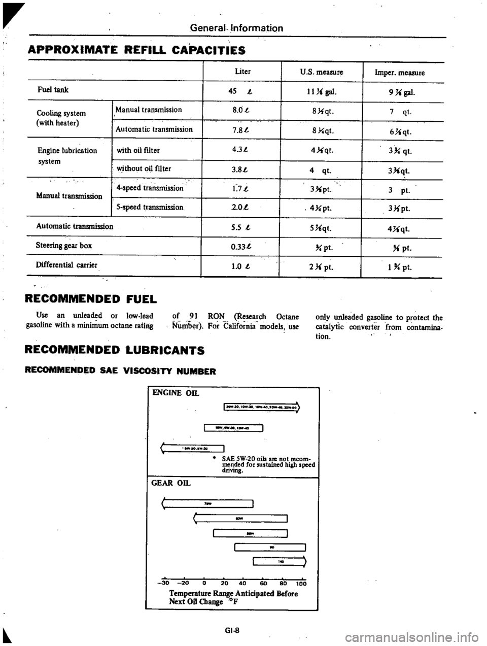
APPROXIMATE
REFILL
CAPACITIES
I
Uter
u
s
measure
Imper
measure
Fuel
tank
I
45
J
IUi
gal
9
Ji
gal
Cooling
system
ManUal
transmission
I
8
0J
I
8Jiqt
7
qt
with
heater
Automatic
tr
smission
I
7
8J
I
8Y
qt
6Jiqt
Engine
lubrication
with
oil
f1lter
I
4
3J
I
4
Ji
qt
3
qt
system
without
oil
f1lter
I
3
8J
I
3Xqt
4
ql
I
4
speed
transmission
I
1
7J
I
3X
pl
3
pI
Manual
transmission
I
5
speed
transmission
I
2
0
I
4Y
pt
3Mpt
Automatic
transmission
I
5
s
J
I
5Uqt
4Uqt
Steering
gear
box
I
0
33J
I
pt
pt
Differential
carrier
I
1
0
J
I
2M
pI
I
pt
RECOMMENDED
FUEL
Use
an
unleaded
or
low
lead
gasoline
with
a
minimum
octane
rating
of
91
RON
Research
Octane
Nuniber
For
California
models
use
only
unleaded
gasoline
to
protect
the
catalytic
converter
from
contamina
tion
RECOMMENDED
LUBRICANTS
RECOMMENDED
SAE
VISCOSITY
NUMBER
C
ENGINE
on
12O
II
O
10Vt4ll
10Wf
2
I
ICWI
I
ao
40
J
SAE
5W
20
oils
ate
not
lecom
mended
for
sustained
high
speed
drivin
GEAR
On
I
J
w
c
30
20
0
20
40
60
80
100
Temperature
Range
Anticipated
Before
Next
Oil
Change
OF
GI
8
Page 20 of 537
r
ManifolJ
nuts
I
2
to
1
6
kg
m
8
7
to
I
6
ft
lb
Carburelor
nuls
0
5
to
1
0
kg
m
3
6
to
7
2
fl
tb
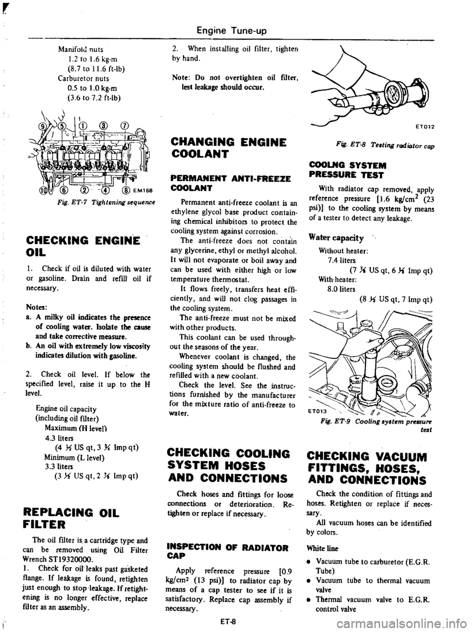
Fig
ET
7
Tightening
s
quence
CHECKING
ENGINE
OIL
Check
if
oil
is
diluled
with
water
or
gasoline
Drain
and
refill
oil
if
necessary
Notes
a
A
milky
oil
indicates
the
presence
of
cooling
water
Isolate
the
cause
and
take
corrective
measure
b
An
oil
with
extremely
low
viscosity
indicates
dilution
with
gasoline
2
Check
oil
level
If
below
the
specified
level
raise
it
up
10
the
H
level
Engine
oil
capacity
including
oil
filter
Maximum
H
leven
4
3
liters
4
MUS
qt
3
Y
Imp
qt
Minimum
L
level
3
3
liters
3
f
US
qt
2
U
Imp
ql
REPLACING
OIL
FILTER
The
oil
mter
is
a
cartridge
type
and
can
be
removed
using
Oil
Filter
Wrench
STI9320000
I
Check
for
oil
leaks
past
gasketed
flange
If
leakage
is
found
retighten
just
enough
to
stop
leakage
If
retight
ening
is
no
longer
effective
replace
mter
as
an
assembly
Engine
Tune
up
2
When
installing
oil
filter
tighlen
by
hand
Note
Do
not
overtighten
oil
flIt
lest
leakage
should
occur
CHANGING
ENGINE
COOLANT
PERMANENT
ANTI
FREEZE
COOLANT
Permanent
anti
freeze
coolant
is
an
ethylene
glycol
base
producl
conlain
ing
chemical
inhibilors
10
protect
the
cooling
system
against
corrosion
The
anti
freeze
does
not
contain
any
glycerine
ethyl
or
methyl
alcohol
It
will
not
evaporate
or
boil
away
and
can
be
used
with
either
high
or
low
temperaturethennoslat
It
flows
freely
transfers
heat
effi
ciently
and
will
not
clog
passages
in
the
cooling
system
The
anti
freeze
must
not
be
mixed
with
other
products
This
coolant
can
be
used
through
out
the
seasons
of
the
year
Whenever
coolant
is
changed
the
cooling
syslem
should
be
flushed
and
refilled
with
a
new
coolant
Check
the
level
See
the
instruc
lions
furnished
by
the
manufacturer
for
the
mixture
ratio
of
anti
freeze
10
water
CHECKING
COOLING
SYSTEM
HOSES
AND
CONNECTIONS
Check
hoses
and
fittings
for
loose
connections
or
deterioration
Re
tighten
or
replace
if
necessary
INSPECTION
OF
RADIATOR
CAP
Apply
reference
pressure
0
9
kg
cm2
13
psi
1
to
radiator
cap
by
means
of
a
cap
tester
to
see
if
it
is
satisfactory
Replace
cap
assembly
if
necessary
ET
8
Fig
ET
fJ
Teltill
l
rod
ioto
cop
COOLNG
SYSTEM
PRESSURE
TEST
With
radiator
cap
removed
apply
reference
pressure
1
6
kg
cm2
23
psi
to
the
cooling
system
by
means
of
a
lesler
to
detect
any
leakage
Water
capacity
Without
heater
7
4
liters
7
U
US
qt
6
f
Imp
qt
With
heater
8
0
liters
8
f
US
qt
7
Imp
qt
CHECKING
VACUUM
FITTINGS
HOSES
AND
CONNECTIONS
Check
the
condition
of
filtings
and
hoses
Retighten
or
replace
if
neces
sary
All
vacuum
hoses
can
be
identified
by
colors
White
line
Vacuwn
tube
to
carburetor
E
G
R
Tube
Vacuum
tube
to
thermal
vacuum
valve
Thennal
vacuum
valve
to
E
G
R
control
valve
Page 36 of 537
Replace
bulb
if
bulb
is
burned
ou
t
If
bulb
is
not
burned
trace
wireis
back
to
ignition
switch
Repair
or
replace
if
necessary
2
Be
sure
that
floor
temperature
is
cool
below
800C
1760F
before
carrying
out
the
following
procedure
1
Remove
rear
seat
2
Ignition
switch
is
turned
to
the
Temperature
sensing
switch
Temperature
warning
lamp
Contact
close
Off
Contact
open
On
Note
Avoid
heating
floor
tempera
ture
sensing
switch
directly
If
lamp
does
not
glow
check
floor
temperature
sensing
switch
connector
for
continuity
with
a
circuit
tester
If
continuity
should
exist
after
heated
surrounding
areas
of
floor
tern
rv
wnTP
sen
cinq
S
Vitch
reolace
tem
perature
sensing
switch
If
continuity
does
not
exist
trace
the
wiring
back
to
relay
or
check
the
following
step
3
Repair
or
replace
wire
s
if
necessary
Note
The
floor
temperature
sensing
switch
may
be
heated
through
the
floor
by
a
proper
heater
3
Turn
ignition
switch
to
the
IG
position
anf
disconnect
floor
temper
ature
sensing
connector
The
lamp
should
remain
on
If
not
check
floor
4
0
3
UJ
GJO
Engine
Tune
up
IGU
position
3
Ensure
that
floor
tem
perature
warning
lamp
goes
out
4
Heat
surrounding
areas
of
floor
temperature
sensing
switch
with
a
proper
heater
to
ensure
that
floor
temperature
warning
lamp
glows
when
floor
is
heated
to
lh
specifications
as
shown
in
the
table
below
Floor
temperature
Below
1050C
22IOF
Above
1050C
2210F
temperature
relay
for
continuity
with
a
circuit
tester
Referring
to
the
following
floor
temperature
relay
if
relay
is
normal
trace
wire
s
back
to
ignition
switch
Repair
faulty
wiring
Floor
temperature
rela
To
check
floor
temperature
relay
remove
it
and
proceed
as
follows
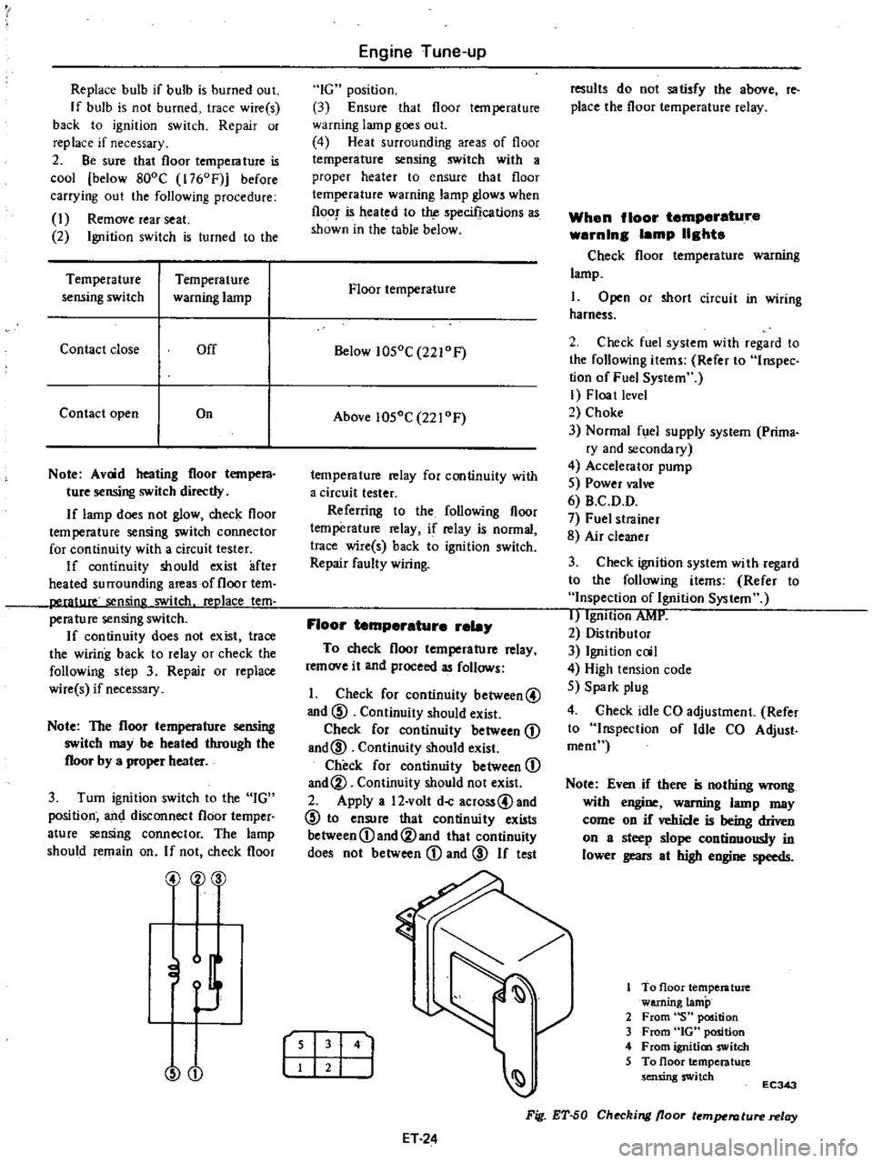
1
Check
for
continuity
between@
and
@
Continuity
should
exist
Check
for
continuity
between
D
and@
Continuity
should
exist
Check
for
continuity
between
D
and@
Continuity
should
not
exist
2
Apply
a
12
volt
doC
across@and
@
to
ensure
that
continuity
exists
between
D
and@and
that
continuity
does
not
between
D
and
@
If
test
r
I
141
ET
24
results
do
not
satisfy
the
above
reo
place
the
floor
temperature
relay
When
floor
temperature
warnln8
lamp
118hts
Check
floor
temperature
warning
lamp
I
Open
or
short
circuit
in
wiring
harness
2
Check
fuel
system
with
regard
to
the
following
items
Refer
to
Inspec
tion
of
Fuel
System
I
Floa
t
level
2
Choke
3
Normal
fuel
supply
system
Prima
ry
and
secondary
4
Accelerator
pump
5
Power
valve
6
B
C
D
D
7
Fuel
strainer
8
Air
cleaner
3
Check
ignition
system
with
regard
to
the
following
items
Refer
to
Inspection
of
Ignition
System
I
IgnItion
AMI
2
Distributor
3
Ignition
coil
4
High
tension
code
5
Spark
plug
4
Check
idle
CO
adjustment
Refer
to
Inspection
of
Idle
CO
Adjust
roeoC
Note
Even
if
there
is
nothing
wrong
with
engine
warning
lamp
may
come
on
if
vehicle
is
being
driven
on
a
steep
slope
continuously
in
lower
gears
at
high
engine
speeds
To
floor
temperature
warning
lamp
2
From
S
position
3
From
GOt
position
4
From
ignition
switch
5
To
floor
temperature
sensing
switch
EC343
Fig
ET
50
Checking
floor
temperature
relay
Page 91 of 537
DESCRIPTION
COOLANT
LEVEL
DRAINING
AND
FLUSHING
THE
COOLING
SYSTEM
WATER
PUMP
REMOVAL
AND
INSTALLATION
DISASSEMBLY
INSPECTION
AND
ADJUSTMENT
TORQUE
COUPLING
REMOVAL
AND
INSTALLATION
DESCRIPTION
The
cooling
system
is
of
the
con
ventional
pressure
type
A
centrifugal
pump
installed
on
the
timing
chain
cover
serves
to
circulate
the
coolant
The
pressure
type
radiator
filler
cap
installed
on
the
radiator
operates
the
cooling
system
at
higher
than
atmos
pheric
pressure
The
higher
pressure
raises
the
boiling
point
of
the
coolant
and
in
Cooling
System
COOLING
SYSTEM
CONTENTS
CO
2
CO
2
OISASSEMBL
Y
INSPECTION
TEM
COUPLlNG
INSPECTION
THERMOSTAT
REMOVAL
AND
INSTALLATION
INSPECTION
RADIATOR
REMOVAL
AND
INSTALLATION
INSPECTION
CO
2
CO
2
CO
3
CO
3
CO
3
CO
3
CO
4
creases
the
cooling
efficiency
of
the
radiator
When
the
thermostat
is
closed
the
coolant
remains
in
the
cylinder
head
and
block
for
swift
warming
up
of
the
engine
After
it
reaches
normal
oper
ating
temperature
the
coolant
circu
lates
through
the
radiator
The
cooling
fan
drive
is
of
a
coupling
type
COOLANT
LEVEL
The
coolant
level
should
be
check
ed
and
maintained
at
SO
mm
1
97
in
below
the
upper
face
of
filler
neck
when
the
engine
is
cold
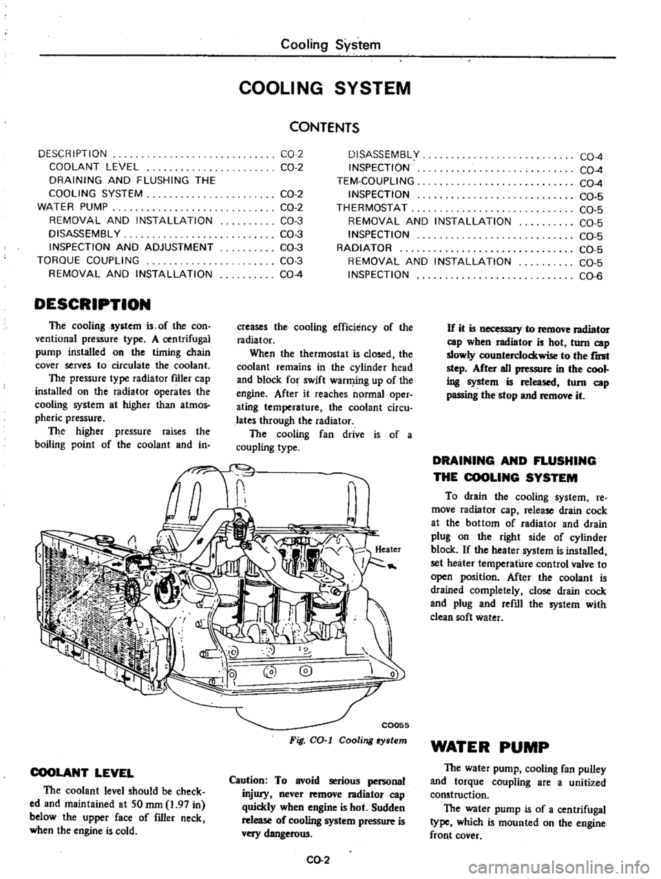
C0055
Fig
CO
I
Cooling
ry
lem
Caution
To
avoid
serious
personal
injury
never
remove
I3diator
cap
quickly
when
engine
is
hot
Sudden
release
of
cooling
system
pressure
is
very
dangerous
CO
2
CO
4
CO
4
CO
4
CO
5
CO
5
CO
5
CO
5
CO
5
CO
5
CO
6
If
it
is
necessary
to
remove
radiator
cap
wben
radiator
is
hot
turn
cap
slowly
counterclockwise
to
the
r
step
After
all
pressure
in
the
cool
ing
system
is
released
tom
cap
passing
the
stop
and
remove
it
DRAINING
AND
FLUSHING
THE
COOLING
SYSTEM
To
drain
the
cooling
system
re
move
radiator
cap
release
drain
cock
at
the
bottom
of
radiator
and
drain
plug
on
the
right
side
of
cylinder
block
If
the
heater
system
is
installed
set
heater
temperature
control
valve
to
open
position
After
the
coolant
is
drained
completely
close
drain
cock
and
plug
and
refill
the
system
with
clean
soft
water
WATER
PUMP
The
water
pump
cooling
fan
pulley
and
torque
coupling
are
a
unitized
construction
The
water
pump
is
of
a
centrifugal
type
which
is
mounted
on
the
engine
front
cover
Page 95 of 537
r
direction
when
hoses
are
assembled
3
Ensure
that
clearance
between
radiator
hose
and
any
adjacent
parts
is
30
mm
I
181
in
minimum
On
mod
els
equipped
with
air
conditions
a
minimum
clearance
of
18
mm
0
709
in
should
exist
between
compressor
and
hose
4
Ensure
that
clearance
between
shroud
and
fan
is
even
at
any
place
Note
Be
careful
not
to
damage
radia
tor
fins
and
core
tube
when
in
stalling
INSPECTION
Radiator
cap
should
be
checked
for
working
pressure
at
regular
tune
up
intervals
First
check
rubber
seal
on
cap
for
tears
cracks
or
deterioration
Cooling
System
after
cleaning
it
Then
install
radiator
cap
on
a
tester
If
cap
does
not
hold
or
will
not
release
at
the
specified
pres
sure
replace
cap
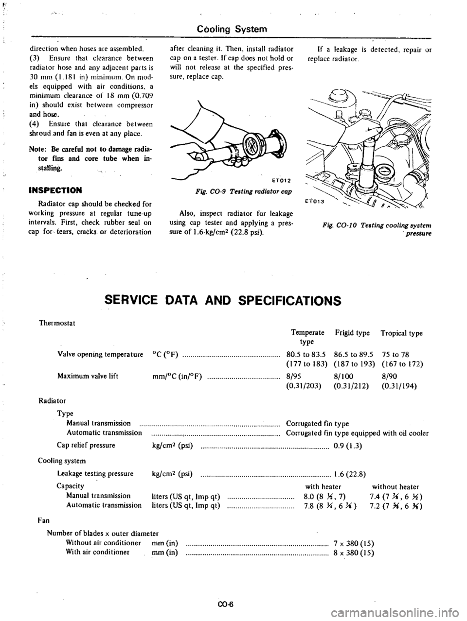
Fig
CO
9
Telting
radiator
cap
Also
inspect
radiator
for
leakage
using
cap
tester
and
applying
a
pres
sure
of
1
6
kg
cm
22
8
psi
If
a
leakage
is
detected
repair
or
replace
radiator
Fig
CO
IO
Testing
cooling
6ystem
pUS
ure
SERVICE
DATA
AND
SPECIFICATIONS
Thermostat
Valve
opening
temperature
oC
F
Maximum
valve
lift
mm
oC
inj
F
Radia
tor
Type
Manual
transmission
Automatic
transmission
Cap
relief
pressure
Cooling
system
Leakage
testing
pressure
Capacity
Manual
transmission
Automatic
transmission
Fan
Number
of
blades
x
outer
diameter
Without
air
conditioner
mm
in
With
air
conditioner
mm
in
kg
em
psi
kg
em
psi
liters
US
qt
Imp
qt
liters
US
qt
Imp
qt
CO
6
Temperate
Frigid
type
Tropical
type
type
80
5
to
83
5
86
5
to
89
5
75
to
78
177
to
183
187
to
193
167
to
172
8
95
8
100
8
90
0
31
203
0
31
212
0
31
194
Corrugated
fin
type
Corrugated
fin
type
equipped
with
oil
cooler
0
9
1
3
1
6
22
8
with
heater
8
0
8
Ii
7
7
8
8
Y
6
J
i
without
heater
74
7J
i6
1i
7
2
7
X
6
X
7
x
380
15
8
x
380
15
Page 96 of 537
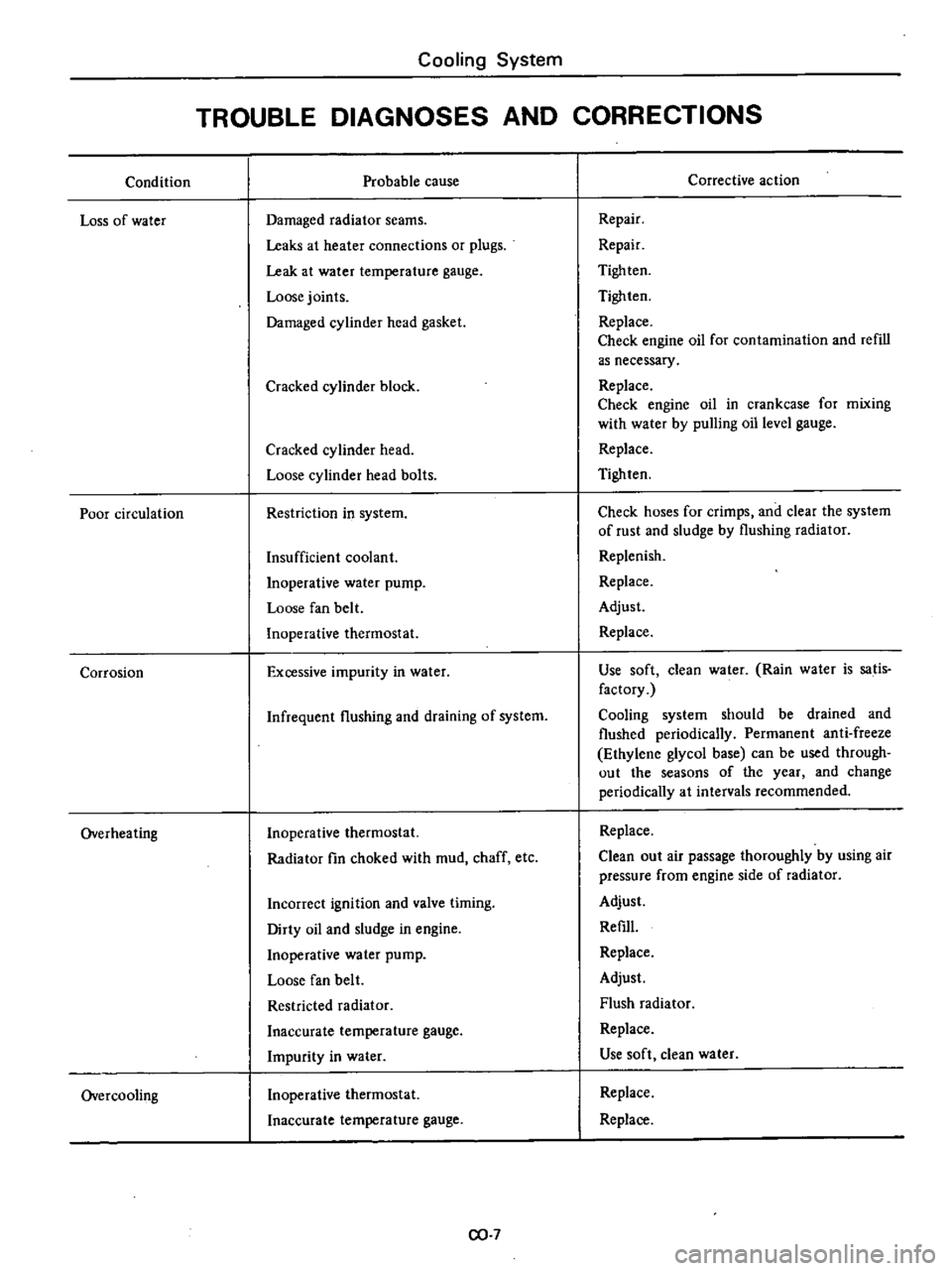
Condition
Loss
of
water
Poor
circulation
Corrosion
Overheating
Overcooling
Cooling
System
TROUBLE
DIAGNOSES
AND
CORRECTIONS
Probable
cause
Damaged
radiator
seams
Leaks
at
heater
connections
or
plugs
Leak
at
water
temperature
gauge
Loose
joints
Damaged
cylinder
head
gasket
Cracked
cylinder
block
Cracked
cylinder
head
Loose
cylinder
head
bolts
Restriction
in
system
Insufficient
coolant
Inoperative
water
pump
Loose
fan
belt
Inoperative
thermostat
Excessive
impurity
in
water
Infrequent
flushing
and
draining
of
system
Inoperative
thermostat
Radiator
fin
choked
with
mud
chaff
etc
Incorrect
ignition
and
valve
timing
Dirty
oil
and
sludge
in
engine
Inoperative
water
pump
Loose
fan
belt
Restricted
radiator
Inaccurate
temperature
gauge
Impurity
in
water
Inoperative
thermostat
Inaccurate
temperature
gauge
CO
7
Corrective
action
Repair
Repair
Tigh
ten
Tighten
Replace
Check
engine
oil
for
contamination
and
refill
as
necessary
Replace
Check
engine
oil
in
crankcase
for
mixing
with
water
by
pulling
oil
level
gauge
Replace
Tighten
Check
hoses
for
crimps
and
clear
the
system
of
rust
and
sludge
by
flushing
radiator
Replenish
Replace
Adjust
Replace
Use
soft
clean
water
Rain
water
is
satis
factory
Cooling
system
should
be
drained
and
flushed
periodically
Permanent
anti
freeze
Ethylene
glycol
base
can
be
used
through
out
the
seasons
of
the
year
and
change
periodically
at
intervals
recommended
Replace
Clean
out
air
passage
thoroughly
by
using
air
pressure
from
engine
side
of
radiator
Adjust
Refill
Replace
Adjust
Flush
radiator
Replace
Use
soft
clean
water
Replace
Replace
Page 116 of 537
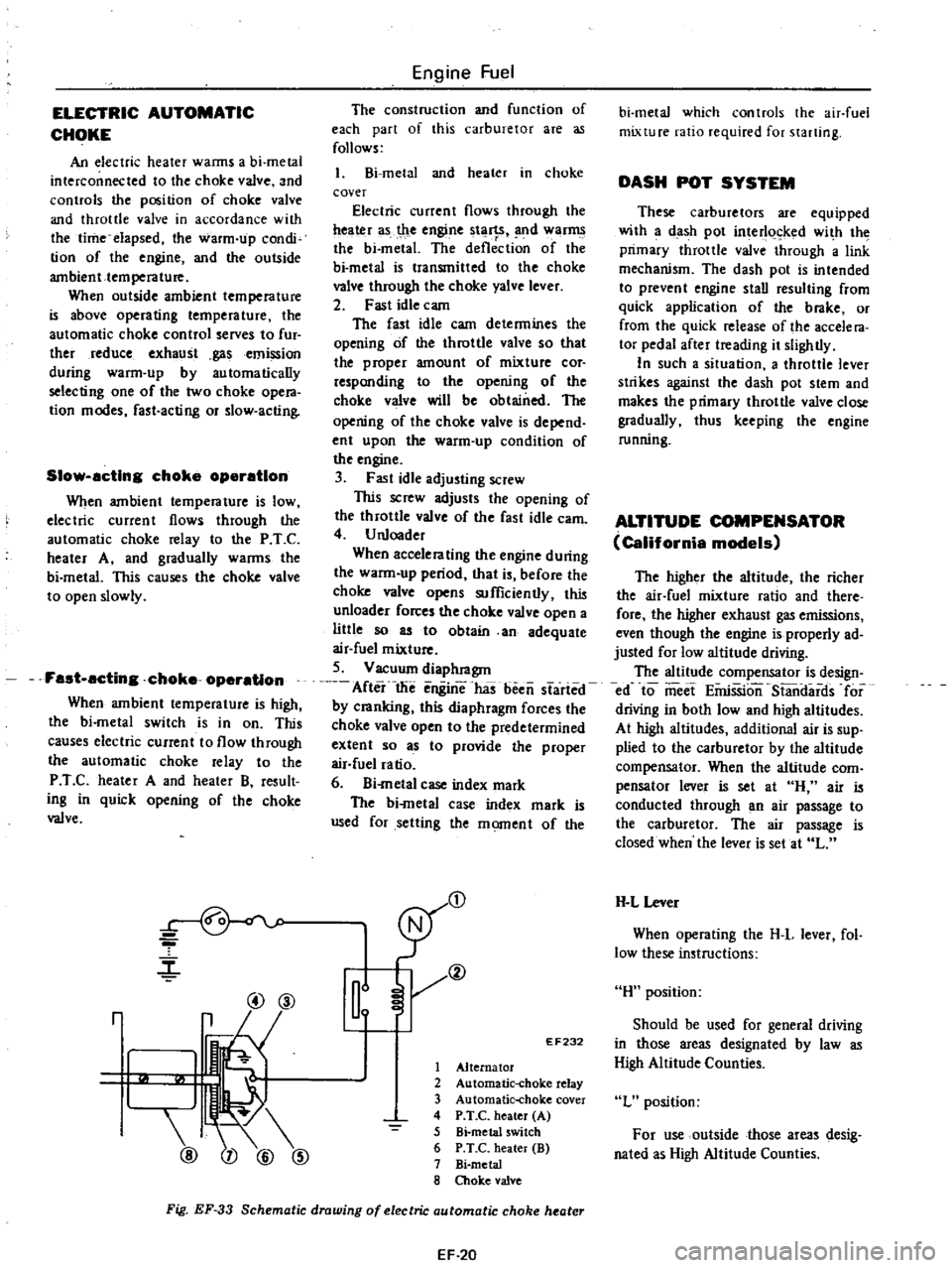
ELECTRIC
AUTOMATIC
CHOKE
An
electric
heater
wanns
a
bi
metal
interconnected
to
the
choke
valve
and
controls
the
position
of
choke
valve
and
throttle
valve
in
accordance
with
the
time
elapsed
the
warm
up
condi
tion
of
the
engine
and
the
outside
ambient
temperature
When
outside
ambient
temperature
is
above
operating
temperature
the
automatic
choke
control
serves
to
fur
ther
reduce
exhaust
gasemission
during
warm
up
by
automatically
selecting
one
of
the
two
choke
opera
tion
modes
fast
acting
or
slow
acting
Slow
acting
choke
operation
When
ambient
temperature
is
low
electric
current
flows
through
the
automatic
choke
relay
to
the
P
T
C
heater
A
and
gradually
warms
the
bi
metal
This
causes
the
choke
valve
to
open
slowly
Fast
acting
choke
operation
When
ambient
temperature
is
high
the
bi
metal
switch
is
in
on
This
causes
electric
current
to
flow
through
the
automatic
choke
relay
to
the
P
T
C
heater
A
and
heater
B
result
ing
in
quick
opening
of
the
choke
valve
r
@@
r
@
Engine
Fuel
The
construction
and
function
of
each
part
of
this
carburetor
are
as
follows
l
Bi
metal
and
heater
in
choke
cover
Electric
current
flows
through
the
ttea
r
as
t
le
engine
tl
1
SI
nd
war
the
bi
metal
The
deflection
of
the
bi
metal
is
transmitted
to
the
choke
valve
through
the
choke
yalve
lever
2
Fast
idle
cam
The
fast
idle
cam
determines
the
opening
of
the
throttle
valve
so
that
the
proper
amount
of
mixture
cor
responding
to
the
opening
of
the
choke
valve
will
be
obtained
The
opening
of
the
choke
valve
is
depend
ent
upon
the
warm
up
condition
of
the
engine
3
Fast
idle
adjusting
screw
This
screw
adjusts
the
opening
of
the
throttle
valve
of
the
fast
idle
earn
4
U
nloader
When
accelerating
the
engine
during
the
warm
up
period
that
is
before
the
choke
valve
opens
sufficiently
this
unloader
forces
the
choke
valve
open
a
liUle
so
as
to
obtain
an
adequate
air
fuel
mixture
5
Vacuum
diaphragm
After
the
enginThas
been
started
by
cranking
this
diaphragm
forces
the
choke
valve
open
to
the
predetermined
extent
so
as
to
provide
the
proper
air
fuel
ratio
6
Bi
metal
case
index
mark
The
bi
metal
case
index
mark
is
used
for
setting
the
moment
of
the
D
Il
EF232
1
Alternator
2
Automatic
choke
relay
3
Automatic
choke
cover
4
P
T
C
heater
A
5
Bi
metal
switch
6
P
T
C
heater
B
7
Bi
metal
8
Choke
valve
Fig
EF
33
Schematic
drawing
of
electric
automatic
choke
heater
EF
20
bi
metal
which
controls
the
air
fuel
mixture
ratio
required
for
starting
DASH
POT
SYSTEM
These
carburetors
are
equipped
with
a
dash
pot
interl
ked
wi
h
the
primary
throttle
valve
through
a
link
mechanism
The
dash
pot
is
intended
to
prevent
engine
stall
resulting
from
quick
application
of
the
brake
or
from
the
quick
release
of
the
accele
ra
tor
pedal
after
treading
it
slightly
In
such
a
situation
a
throttle
lever
strikes
against
the
dash
pot
stem
and
makes
the
primary
throttle
valve
close
gradually
thus
keeping
the
engine
running
ALTITUDE
COMPENSATOR
California
models
The
higher
the
altitude
the
richer
the
air
fuel
mixture
ratio
and
there
fore
the
higher
exhaust
gas
emissions
even
though
the
engine
is
properly
ad
justed
for
low
altitude
driving
The
altitude
compensator
is
design
ed
to
meet
EiiriSSion
S13ndards
for
driving
in
both
low
and
high
altitudes
At
high
altitudes
additional
air
is
sup
plied
to
the
carburetor
by
the
altitude
compensator
When
the
altitude
com
pensator
lever
is
set
at
H
air
is
conducted
through
an
air
passage
to
the
carburetor
The
air
passage
is
closed
when
the
lever
is
set
at
L
H
L
Lever
When
operating
the
H
L
lever
fol
low
these
instructions
H
position
Should
be
used
for
general
driving
in
those
areas
designated
by
law
as
High
Altitude
Counties
L
position
For
use
outside
those
areas
desig
nated
as
High
Altitude
Counties
Page 120 of 537

ELECTRIC
AUTOMATIC
CHOKE
Checklna
automatic
choke
heater
circuit
with
function
test
connector
Caution
Do
not
altach
test
leads
of
a
circuit
tester
to
those
other
than
designated
Refer
to
figure
Ef
43
I
With
engine
not
running
check
for
continuity
between
A
and
B
as
shown
in
figure
Ef
43
If
continuity
exists
heater
is
func
tioning
properly
If
continuity
d
s
not
exist
check
for
disconnected
connector
or
open
P
T
e
heater
circuit
2
With
engine
running
at
idle
check
for
presence
of
voltage
across
A
and
B
as
shown
in
figure
EF
43
If
voltmeter
reading
is
12
volts
d
c
heater
circuit
is
functioning
properly
If
vohmeter
reading
is
zero
check
for
disconnected
connector
open
circuit
or
faulty
automatic
choke
relay
3
Replace
faulty
parts
J
j
N
j
EF710
1
ignition
key
2
Automatic
choke
relay
Engine
stop
OFF
Engine
start
ON
3
Automatic
choke
heateI
4
Function
test
connector
5
Altema
tor
Fig
EF
43
Checking
oulomalic
choke
heater
circuit
with
fu
nc
non
led
connector
Engine
Fuel
Automatic
choke
I
Before
starting
engine
fully
de
press
al
celerator
pedaJ
to
ensure
that
choke
valve
doses
properly
Push
choke
valve
with
a
finger
and
heck
for
binding
3
Check
0
be
sure
that
bi
rnetal
cover
index
mark
is
set
at
the
cen
leT
of
choke
housing
index
mark
a
s
shown
in
Figure
EF
44
Note
Do
not
set
b
metal
cover
index
mark
at
any
position
except
the
center
of
choke
housing
index
marl
tE
jL
J
Thermostat
cover
Bi
metal
chamber
2
Thermostat
housing
3
Groove
ET034
Fig
EF
44
Bi
metol
tting
4
Check
automatic
choke
heater
source
wiring
for
proper
connection
then
start
engine
5
After
warming
up
the
engine
see
that
choke
valve
is
fully
open
6
If
automatic
choke
heater
source
wiring
is
normal
and
choke
valve
does
not
operate
after
warm
up
replace
hi
metal
co
t
er
Automatic
choke
relay
I
Remove
automatic
choke
relay
Auto
choke
heater
relay
EF278
Fig
EF
45
Location
of
automatic
choke
relay
EF
24
2
Make
an
operational
check
of
automatic
choke
relay
as
shown
in
Figure
EF
46
Apply
2
volts
d
c
across
termi
nals
I
and
3
to
ensure
that
i
ontinuity
exists
between
terminals
2
and
4
Check
t
lal
continuity
does
not
exist
between
terminals
2
and
4
when
no
voltage
is
applied
across
them
If
results
satisfies
the
above
automatic
choke
relay
is
functioning
properly
if
not
replace
choke
relay
1
2
3
y
4
EF723
Fig
EF
46
Checking
automatic
choke
relay
Automatic
choke
heater
I
Measure
resistance
of
choke
heater
as
shown
in
figure
EF
47
spe
ified
re
s
an
ce
is
3
7
to
8
9
ohms
F
EF261
Fig
EF
47
Automatic
choke
heater
check
2
If
measured
value
is
not
within
the
specification
replace
bi
metal
cover
INTERLOCK
OPENING
OF
PRIMARY
AND
SECONDARY
THROTnE
VALVE
Figure
EF
48
shows
primary
throt
tie
valve
opened
SO
When
primary
throtlle
valve
is
opened
50
the
adjust
plate
integrated
with
throttle
valve
is
in
contact
with
return
plate
at
A
Page 162 of 537
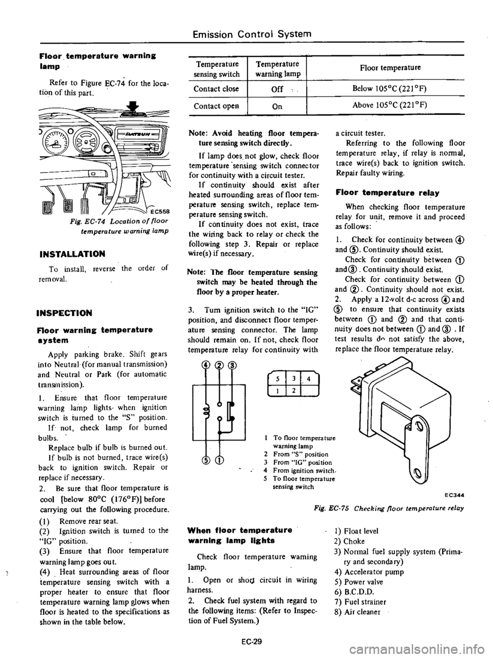
Floor
temparature
warning
lamp
Refer
to
Figure
EC
74
for
the
loca
tion
of
this
part
L
1t
1
RAt
Fig
EC
74
Location
of
floor
temperature
warning
lamp
INSTALLATION
To
install
reverse
the
order
of
rem
ovaL
INSPECTION
Floor
warning
temperature
system
Apply
parking
brake
Shift
gears
into
Neutral
foI
manual
transmission
and
Neutral
or
Park
for
automatic
transmission
1
Ensure
that
floor
temperature
warning
lamp
lights
when
ignition
switch
is
iumed
to
the
S
position
If
not
check
lamp
for
burned
bulbs
Replace
bulb
if
bulb
is
burned
out
If
bulb
is
not
burned
trace
wire
s
back
to
ignition
switch
Repair
or
replace
if
necessary
2
Be
sure
that
floor
temperature
is
cool
below
800C
1760Fj
before
carrying
out
the
following
procedure
I
Remove
rearseat
2
Ignition
switch
is
turned
to
the
IG
position
3
Ensure
that
floor
temperature
warning
lamp
goes
out
4
Heat
surrounding
areas
of
floor
temperature
sensing
switch
with
a
proper
heater
to
ensure
that
floor
temperature
warning
lamp
glows
when
floor
is
heated
to
the
specifications
as
shown
in
the
table
below
Emission
Control
System
Temperature
sensing
switch
Contact
close
Temperature
warning
lamp
Off
Contact
open
On
Note
Avoid
heating
floor
tempera
ture
sensing
switch
directly
If
lamp
does
not
glow
check
floor
temperature
sensing
switch
connector
for
continuity
with
a
circuit
tester
If
continuity
should
exist
after
heated
surrounding
areas
of
floor
tem
perature
sensing
switch
replace
tem
perature
sensing
switch
If
con
tinuity
does
not
exist
trace
the
wiring
back
to
relay
or
check
the
following
step
3
Repair
or
replace
wire
s
if
necessary
Note
The
floor
temperature
sensing
switch
may
be
heated
through
the
floor
by
a
proper
heater
3
Turn
ignition
switch
to
the
IG
position
and
disconnect
floor
temper
ature
sensing
connector
The
lamp
should
remain
on
If
not
check
floor
temperature
relay
for
continuity
with
2
00
r
I
141
J
To
floor
temperatwe
warning
lamp
2
From
S
position
3
From
IG
position
4
From
ignition
switch
5
To
floor
temperature
sensing
switch
O
When
floor
temperature
warning
lamp
lights
Check
floor
temperature
warning
lamp
1
Open
or
shorj
circuit
in
wiring
harness
2
Check
fuel
system
with
regard
to
the
following
items
Refer
to
Inspec
lion
of
Fuel
System
EC
29
Floor
temperature
Below
1050C
221
OF
Above
1050C
221
OF
a
circuit
tester
Referring
to
the
following
floor
temperature
relay
if
relay
is
normal
trace
wire
s
back
to
ignition
switch
Repair
faulty
wiring
Floor
temperature
relay
When
checking
floor
temperature
relay
for
unit
remove
it
and
proceed
as
follows
1
Check
for
continuity
between
@
and
ID
Continuity
should
exist
Check
for
continuity
between
CD
and@
Continuity
should
exist
Check
for
continuity
between
CD
and
@
Continuity
should
not
exist
2
Apply
a
12
volt
doc
across
@
and
ID
to
ensure
that
continuity
exists
between
CD
and
@
and
that
con
ti
nuity
does
not
between
CD
and
@
If
test
results
dn
not
satisfy
the
above
replace
the
floor
temperature
relay
EC344
Fig
EC
75
Checking
floor
temperature
relay
1
Float
level
2
Choke
3
Normal
fuel
supply
system
Prima
ry
and
secondary
4
Accelerator
pump
5
Power
valve
6
B
C
D
D
7
Fuel
strainer
8
Air
cleaner
Page 219 of 537
Engine
Removal
Installation
ENGINE
REMOVAL
AND
INSTAllATION
REMOVAL
INSTALLATION
ENGINE
MOUNTING
INSULATORS
REMOVAL
It
is
much
easier
to
remove
engine
and
transmission
as
a
single
unit
than
to
remove
them
separately
After
re
moval
engine
can
be
separated
from
transntission
assembly
Notes
a
Be
sure
to
hoist
engine
and
jack
up
transmission
in
a
safe
manner
b
Use
fender
cove
to
protect
vehicle
body
1
Remove
battery
2
Scribe
hood
hinge
location
for
proper
reinstallation
and
remove
hood
Note
Have
an
assistant
help
you
so
as
to
prevent
damage
to
body
3
Drain
radiator
coolant
4
Disconnect
upper
and
lower
radiator
hoses
from
engine
5
Remove
two
oil
cooler
hoses
from
lower
end
of
radiator
Auto
ma
tic
transmission
models
only
6
Remove
radiator
shroud
7
Remove
four
bolts
securing
radia
tor
and
detach
radiator
Note
Always
tighten
securing
bolt
at
upper
right
hand
side
together
with
body
harness
terminal
8
Remove
carburetor
air
cleaner
as
follows
Remove
fresh
air
duct
Remove
hot
air
duct
Loosen
air
cleaner
band
bolt
and
air
cleaner
supporting
bolts
Disconnect
air
cleaner
ta
air
pump
hose
Disconnect
air
cleaner
to
rocker
cover
hose
at
rocker
cover
Disconnect
air
cleaner
to
air
control
valve
hose
California
models
only
CONTENTS
ER
2
ER
3
ER
3
FRONT
INSULATOR
REAR
INSULATOR
TIGHTENING
TORQUE
ER
4
ER
4
ER
4
Disconnect
air
deaner
to
A
B
valve
hose
Disconnect
air
cleaner
ta
vacuum
hoses
Note
Protect
carburetor
from
dust
and
foreign
matter
by
placing
cover
over
air
inlet
opening
9
Disconnect
fuel
pump
to
fuel
fdter
hose
and
return
hose
10
Disconnect
carbon
canister
hose
on
engine
side
II
Disconnect
air
pump
air
C1eaner
to
al
p
p
hose
12
Disconnect
following
cables
wires
and
hoses
Engine
ground
cable
Accelerator
wire
at
carburetor
High
tension
cable
between
ignition
coil
and
distributor
Wire
to
distributor
at
body
ter
minal
Wire
to
oil
pressure
switch
Wires
to
thermal
transmitter
Wires
to
B
C
p
D
cut
solenoid
Non
California
models
only
auto
choke
heater
and
anti
dieseling
solenoid
Wires
to
alternator
Wires
to
starter
motor
Heater
inlet
and
outlet
hoses
if
so
equipped
Vacuum
hose
of
Master
Vac
at
in
taJce
manifold
Wires
for
back
up
lamp
switch
Cable
to
speedometer
13
Remove
transmission
control
linkage
from
transmission
Manual
transmission
models
I
Detach
rubber
boot
2
Remove
E
ring
and
control
lever
pin
from
transmission
striking
rod
guide
and
remove
control
lever
ER
2
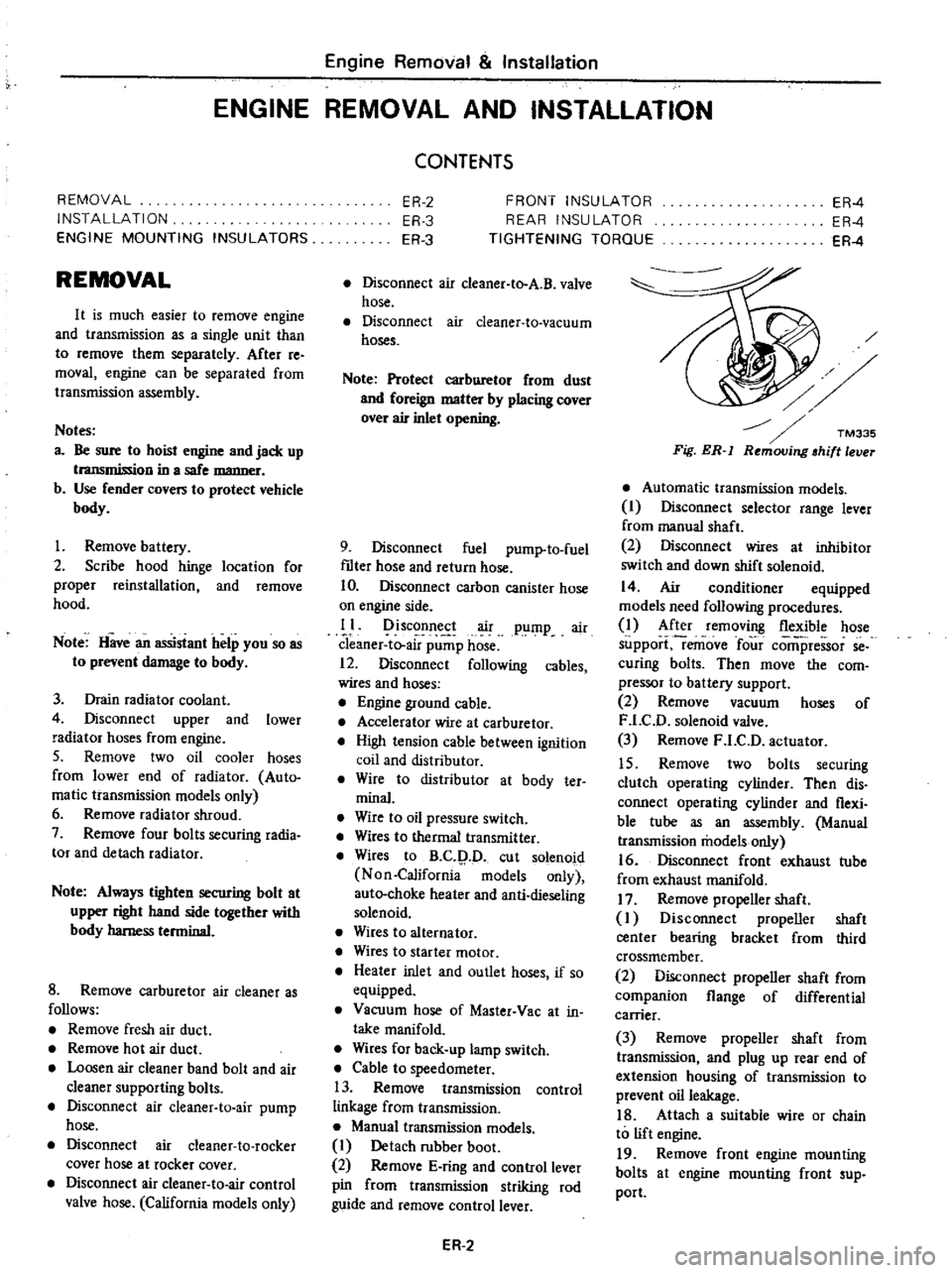
Fig
ER
l
Automatic
transmission
models
I
Disconnect
selector
range
lever
from
manual
shaft
2
Disconnect
wires
at
inhibitor
switch
and
down
shift
solenoid
14
Air
conditioner
equipped
models
need
following
procedures
1
After
removing
flexible
hose
support
remove
four
comi
ressor
se
curing
bolts
Then
move
the
com
pressor
to
battery
support
2
Remove
vacuum
hoses
of
F
LC
D
solenoid
valve
3
Remove
F
LC
D
actuator
15
Remove
two
bolts
securing
clutch
operating
cylinder
Then
dis
connect
operating
cylinder
and
flexi
ble
tube
as
an
assembly
Manual
transmission
models
only
16
Disconnect
front
exhaust
tube
from
exhaust
manifold
17
Remove
propeller
shaft
I
Disconnect
propeller
shaft
center
bearing
bracket
from
third
crossmember
2
Disconnect
propeller
shaft
from
companion
flange
of
differential
carrier
3
Remove
propeller
shaft
from
transmission
and
plug
up
rear
end
of
extension
housing
of
transmission
to
prevent
oil
leakage
18
Attach
a
suitable
wire
or
chain
to
lift
engine
19
Remove
front
engine
mounting
bolts
at
engine
mounting
front
sup
port