check engine DATSUN PICK-UP 1977 User Guide
[x] Cancel search | Manufacturer: DATSUN, Model Year: 1977, Model line: PICK-UP, Model: DATSUN PICK-UP 1977Pages: 537, PDF Size: 35.48 MB
Page 27 of 537
Engine
Tune
up
EC284
When
installing
this
valve
ensure
that
it
properly
oriented
This
valve
should
be
replaced
periodically
Refer
to
Maintenance
Schedule
I
To
distribut0
From
carburetor
Yl
r
EC278
l
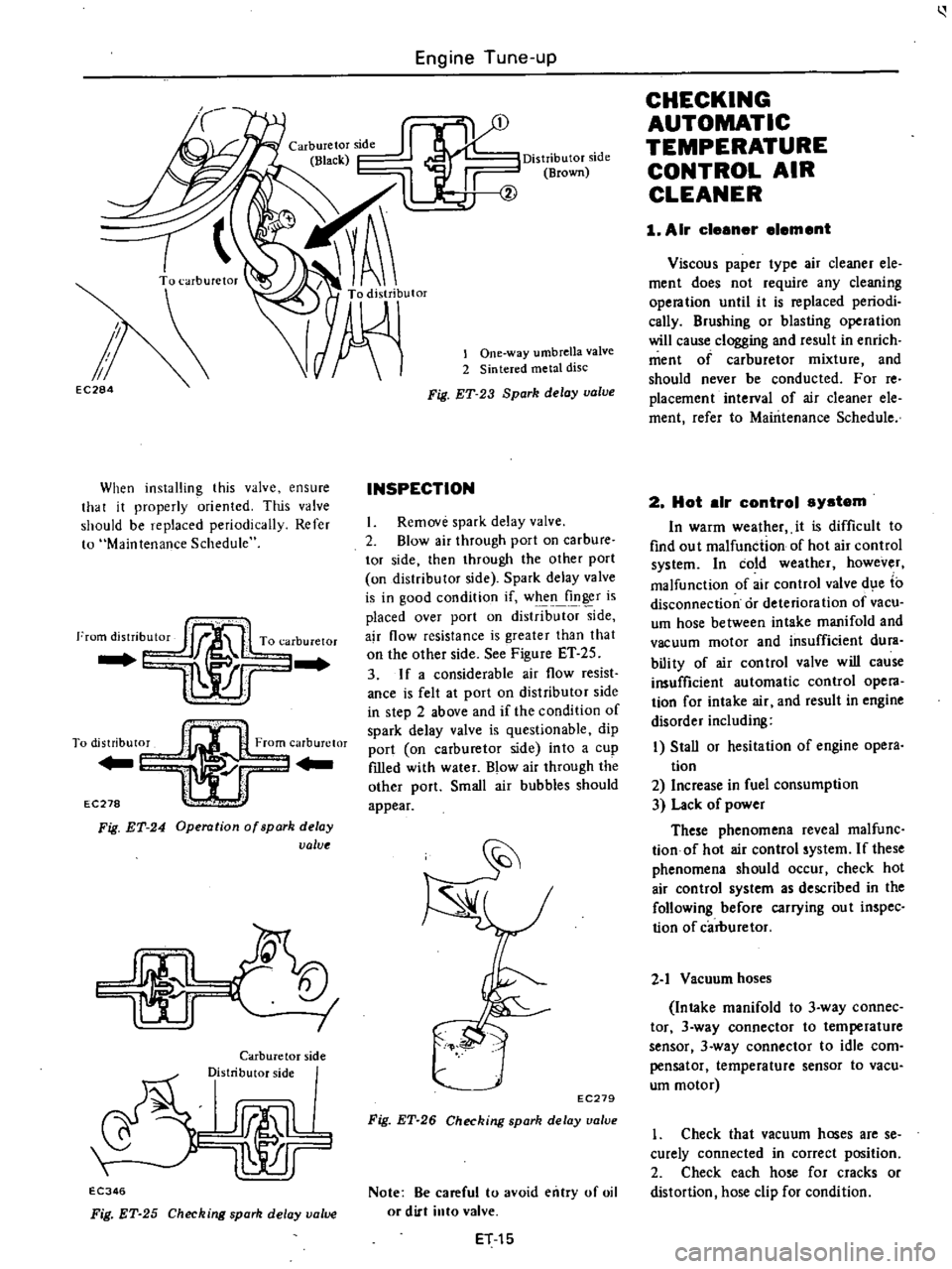
Fig
ET
24
Operation
of
spark
delay
value
I
I
Carburetor
side
Distributor
side
rJmlL
lr
EC346
Fig
ET
25
Checking
spark
delay
value
Distributor
side
Brown
lOne
way
umbrella
valve
2
Sintered
metal
disc
Fig
ET
23
Spark
delay
valve
INSPECTION
I
Remove
spark
delay
valve
2
Blow
air
through
port
on
carbure
tor
side
then
through
the
other
port
on
distributor
side
Spark
delay
valve
is
in
good
condition
if
when
finger
is
placed
over
port
on
distrib
side
ajr
flow
resistance
is
greater
than
that
on
the
other
side
See
Figure
ET
25
3
If
a
considerable
air
flow
resist
ance
is
felt
at
port
on
distributor
side
in
step
2
above
and
if
the
condition
of
spark
delay
valve
is
questionable
dip
port
on
carburetor
side
into
a
cup
fIlled
with
water
Blow
air
through
the
other
port
Small
air
bubbles
should
appear
EC279
Fig
ET
26
Checking
spark
delay
ualue
Note
Be
careful
to
avoid
entry
of
oil
or
dirt
into
valve
ET
15
CHECKING
AUTOMATIC
TEMPERATURE
CONTROL
AIR
CLEANER
1
Air
cleener
element
Viscous
paper
type
air
cleaner
ele
ment
does
not
require
any
cleaning
opera
tion
until
it
is
replaced
periodi
cally
Brushing
or
blasting
operation
will
cause
clogging
and
result
in
enrich
ment
of
carburetor
mixture
and
should
never
be
conducted
For
reo
placement
interval
of
air
cleaner
ele
ment
refer
to
Maintenance
Schedule
2
Hot
elr
control
system
In
warm
wealher
it
is
difficult
to
find
ou
t
malfunction
of
hot
air
control
system
In
cold
weather
however
malfunction
of
air
control
valve
d
e
to
disconnection
or
deterioration
of
vacu
um
hose
between
intake
manifold
and
vacuum
motor
and
insufficient
dura
bili
ty
of
air
con
trol
valve
will
cause
insufficient
automatic
control
opera
tion
for
intake
air
and
result
in
engine
disorder
including
I
Stall
or
hesitation
of
engine
opera
tion
2
Increase
in
fuel
consumption
3
Lack
of
power
These
phenomena
reveal
malfunc
tionof
hot
air
control
system
If
these
phenomena
should
occur
check
hot
air
control
system
as
described
in
the
following
before
carrying
ou
t
inspec
tion
of
carburetor
2
1
Vacuum
hoses
Intake
manifold
to
3
way
connec
tor
3
way
connector
to
temperature
sensor
3
way
connector
to
idle
com
pensator
temperature
sensor
to
vacu
um
motor
1
Check
that
vacuum
hoses
are
se
curely
connected
in
correct
position
2
Check
each
hose
for
cracks
or
distortion
hose
clip
for
condition
Page 28 of 537
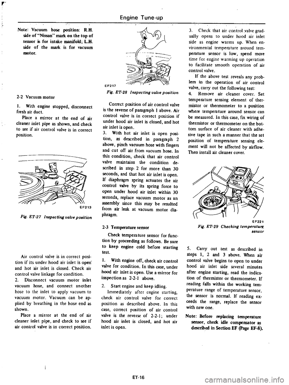
Note
Vacuum
hose
position
R
R
side
of
Nissan
mark
on
the
top
of
sensor
for
intake
manifold
L
R
side
of
the
mark
is
for
vacuum
rootor
2
2
Vacuum
motor
I
With
engine
stopped
disconnect
fresh
air
duct
Place
a
mirror
at
the
end
of
air
cleaner
inlet
pipe
as
shown
and
check
to
see
if
air
control
valve
is
in
correct
position
EF213
Fig
ET
27
Impecting
lJalv
position
Air
control
valve
is
in
correct
posi
tion
if
its
under
hood
air
inlet
is
open
and
hot
air
inlet
is
closed
Check
air
control
valve
linkage
for
condition
2
Disconnect
vacuum
motor
inlet
vacuum
hose
and
connect
another
hose
to
the
inlet
to
apply
vacuum
to
vacuum
motor
Vacuum
can
be
ap
plied
by
breathing
in
the
hose
end
as
shown
Place
a
mirror
at
the
end
of
air
cleaner
inlet
pipe
and
check
to
see
if
air
control
valve
is
in
correct
position
Engine
Tune
up
EF217
Fig
ET
28
lmpecting
value
position
Correct
pC6ition
of
air
control
valve
is
the
reverse
of
paragraph
I
above
Air
control
valve
is
in
correct
position
if
under
hood
air
inlet
is
closed
and
hot
air
inlet
is
open
3
With
hot
air
inlet
is
open
posi
tion
as
descnbed
in
paragraph
2
above
pinch
vacuum
hose
with
fingers
and
cut
of
air
from
vacuum
hose
In
this
condition
check
that
air
control
valve
maintains
the
condition
de
scribed
in
step
2
for
more
than
30
seconds
and
that
hot
air
inlet
is
open
If
diaphragm
spring
actuates
the
air
control
valve
by
its
spring
force
to
open
under
hood
air
inlet
within
30
seconds
replace
vacuum
motor
as
an
assembly
since
this
may
be
resulted
from
air
leak
at
vacuum
motor
dia
phragm
2
3
Temperature
sensor
Check
temperature
sensor
for
func
tion
by
proceeding
as
follows
Be
sure
to
keep
engine
cold
before
starting
test
1
With
engine
off
check
air
control
valve
for
condition
In
this
case
under
hood
air
inlet
is
open
Use
a
mirror
for
inspection
as
2
2
1
above
2
Start
engine
and
keep
idling
Immediately
after
engine
starting
check
air
control
valve
for
correct
position
as
described
above
In
this
case
correct
position
of
air
control
valve
is
the
reverse
of
2
2
1
under
hood
air
inlet
is
closed
and
hot
air
inlet
is
open
ET
16
3
Check
that
air
control
valve
grad
ually
opens
to
under
hood
air
inlet
side
as
engine
warms
up
When
en
vironmental
temperature
around
tern
perature
sensor
is
low
spend
more
time
for
engine
warming
up
operation
to
facilitate
smooth
opera
tion
of
air
con
trol
valve
If
the
above
test
reveals
any
prob
lem
in
the
operation
of
air
control
valve
carry
out
the
following
test
4
Remove
air
cleaner
cover
Set
temperature
sensing
element
of
ther
mistor
or
thermometer
to
a
position
where
tempera
ture
around
sensor
can
be
measured
In
this
case
fix
wiring
of
thermistor
or
thermometer
on
the
bot
tom
surface
of
air
cleaner
with
adhe
sive
tape
in
such
a
manner
that
the
set
position
of
temperature
sensing
ele
ment
will
not
be
affected
by
airflow
Then
install
air
cleaner
cover
EF221
Fig
ET
29
Checking
temperotur
e
ensor
5
Carry
out
test
as
described
in
steps
I
2
and
3
above
When
air
control
valve
begins
to
open
to
under
hood
air
inlet
side
severa
minutes
after
engine
starting
read
the
indica
tion
of
thermistor
or
thermometer
If
reading
falls
within
the
working
tern
perature
range
of
temperature
sensor
the
sensor
is
normaL
If
reading
ex
ceeds
the
range
replace
the
sensor
with
new
one
Note
Before
replacing
temperature
sensor
check
idle
compensator
as
described
in
Section
EF
page
EF
8
Page 29 of 537
OPERATI
NG
PRESSURE
OF
BOOST
CONTROLLED
DECELERATION
DEVICE
B
C
D
D
ADJUSTMENT
CHECKING
a
C
D
D
CIRCUIT
WITH
FUNCTION
TEST
CONNECTOR
Manual
transmission
models
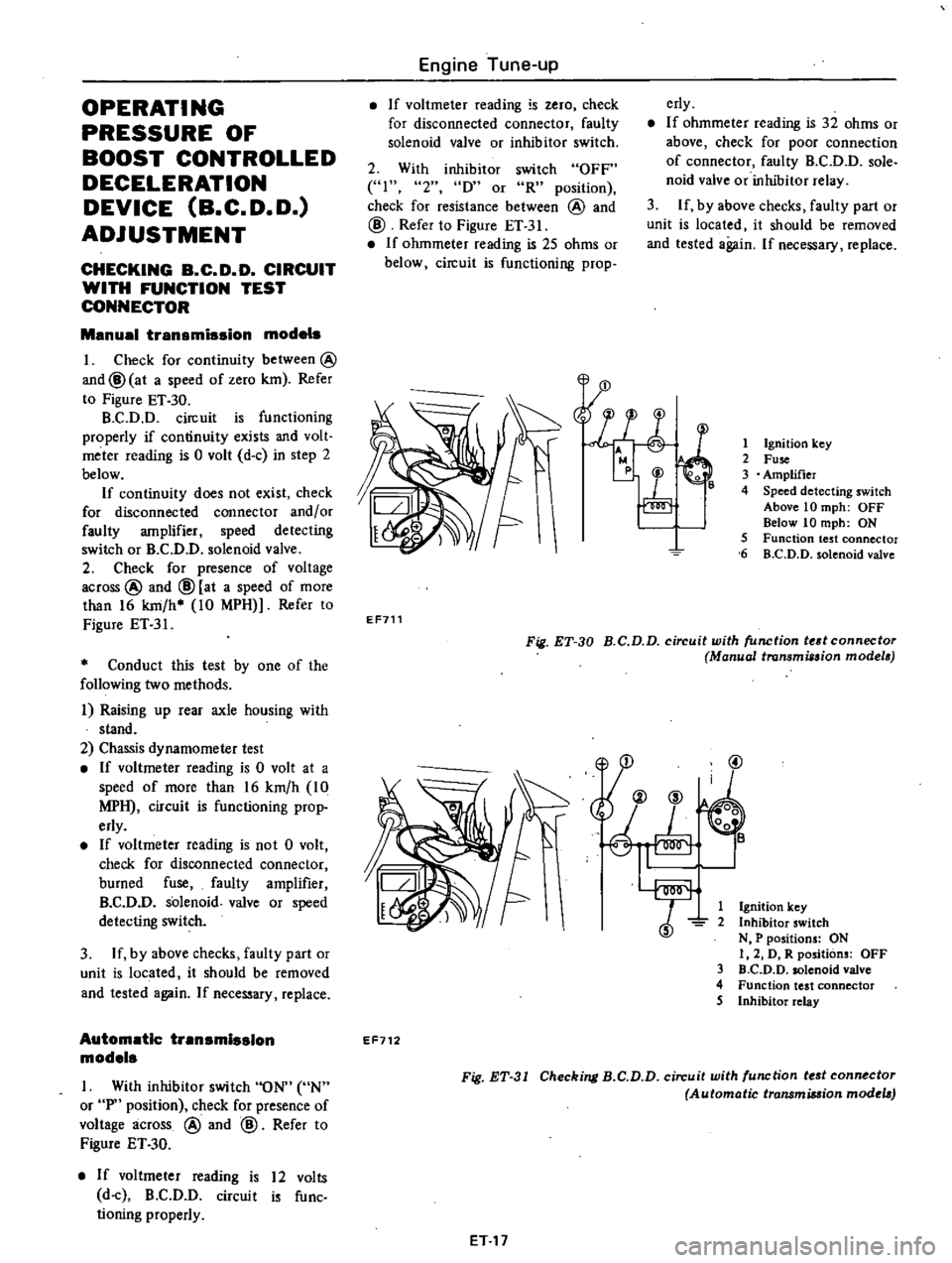
I
Check
for
continuity
between
@
and@
at
a
speed
of
zero
km
Refer
to
Figure
ET
30
B
C
D
D
circuit
is
functioning
properly
if
continuity
exists
and
volt
meter
reading
is
0
volt
d
c
in
step
2
below
If
continuity
does
not
exist
check
for
disconnected
connector
and
or
faulty
amplifier
speed
detecting
switch
or
B
C
D
D
solenoid
valve
2
Check
for
presence
of
voltage
across
@
and
@
at
a
speed
of
more
than
16
km
h
10
MPH
Refer
to
Figure
ET
31
Conduct
this
test
by
one
of
the
following
two
methods
i
Raising
up
rear
axle
housing
with
stand
2
Chassis
dynamometer
test
If
voltmeter
reading
is
0
volt
at
a
speed
of
more
than
16
km
h
10
MPH
circuit
is
functioning
prop
erly
If
voltmeter
reading
is
not
0
volt
check
for
disconnected
connector
burned
fuse
faulty
amplifier
B
C
D
D
solenoid
valve
or
speed
detecting
switch
3
If
by
above
checks
faulty
part
or
unit
is
located
it
should
be
removed
and
tested
again
If
necessary
replace
Automatic
transmission
models
I
With
inhibitor
switch
ON
UN
or
P
position
check
for
presence
of
voltage
across
@
and
@
Refer
to
Figure
ET
30
If
voltmeter
reading
is
12
volts
d
c
B
C
D
D
circuit
is
func
tioning
properly
Engine
Tune
up
If
voltmeter
reading
is
zero
check
for
disconnected
connector
faulty
solenoid
valve
or
inhibitor
switch
erly
If
ohmmeter
reading
is
32
ohms
or
above
check
for
poor
connection
of
connector
faulty
B
C
D
D
sole
noid
valve
or
inhibitor
relay
3
If
by
above
checks
faulty
part
or
unit
is
located
it
should
be
removed
and
tested
again
If
necessary
replace
2
With
inhibitor
switch
OFF
41
2
D
or
R
position
check
for
resistance
between
@
and
@
Refer
to
Figure
ET
31
If
ohmmeter
reading
is
25
ohms
or
below
circuit
is
functioning
prop
l
E
r
1
Ignition
key
2
Fuse
3
Amplifier
4
Speed
detecting
switch
Above
10
mph
OFF
Below
10
mph
ON
5
Function
test
connector
6
B
C
D
D
solenoid
valve
EF711
Fig
ET
30
B
C
D
D
circuit
with
function
tedconnectoT
Manual
transmission
modela
@
1
Ignition
key
2
Inhibitor
switch
N
P
positions
ON
I
2
D
R
positions
OFF
3
D
C
D
D
solenoid
valve
4
Function
test
connector
5
Inhibitor
relay
EF712
Fig
ET
31
Checking
B
C
D
D
circuit
with
function
tf
st
connf
ctor
Automatic
transmiMion
modtla
ET
17
Page 30 of 537
r
ADJUSTMENT
OF
SET
PRESSURE
OF
BOOST
CONTROLLED
DECELERATION
DEVICE
B
C
D
D
Generally
it
is
unnecessary
to
ad
just
the
B
C
D
D
however
if
it
should
become
necessary
to
adjust
it
the
procedure
is
as
follows
Prepare
the
foUowlnB
tools
I
Tachometer
to
measure
the
en
gine
speed
while
idling
and
a
screw
driver
2
A
vacuum
gauge
connecting
pipe
Note
A
qui
k
response
type
boost
gauge
such
as
Bourdon
s
type
is
recommended
a
mercury
type
manometer
should
not
be
used
To
properly
set
the
B
C
D
D
set
pressure
proceed
as
follows
I
Remove
the
harness
of
solenoid
valve
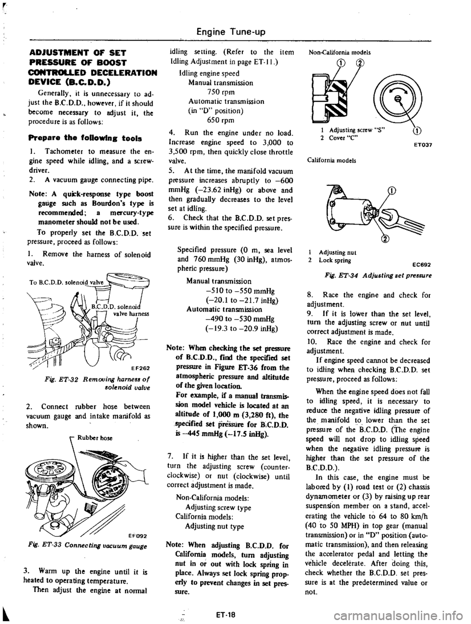
TO
D
D
solenrod
VT
FJ
1
B
C
D
D
solenni
valve
harness
J
ri
y
EF262
F
g
ET
32
Removing
harneS5
of
solenoid
valve
2
Connect
rubber
hose
between
vacuum
gauge
and
intake
manifold
as
shown
Fig
ET
33
Connecting
vacuum
gauge
3
Warm
up
the
engine
until
it
is
heated
to
operating
temperature
Then
adjust
the
engine
at
normal
Engine
Tune
up
idling
setting
Refer
to
the
item
Idling
Adjustment
in
page
ET
II
Idling
engine
speed
Manual
transmission
750
rpm
Automatic
transmission
in
D
position
650
rpm
4
Run
the
engine
under
no
load
Increase
engine
speed
to
3
000
to
3
500
rpm
then
quickly
close
throttle
valve
5
At
the
time
the
manifold
vacuum
pressure
increases
abruptly
to
600
mmHg
23
62
inHg
or
above
and
then
gradually
decreases
to
the
level
set
at
idling
6
Check
that
the
B
C
D
D
set
pres
sure
is
within
the
specified
pressure
Specified
pressure
0
m
sea
level
and
760
mmHg
30
inHg
atmos
pheric
pressure
Manual
transmission
510
to
550
mmHg
20
1
to
21
7
inHg
Automatic
transmission
490
to
530
mmHg
19
3
to
20
9
inHg
Note
When
checking
the
set
pressure
of
B
C
D
D
find
the
specified
set
pressure
in
Figure
IT
36
from
the
atmospheric
pressure
and
altitutde
of
the
given
location
For
example
if
a
manual
transmis
sion
model
vehicle
is
located
at
an
altitude
of
1
000
m
3
280
ft
the
specified
set
preSsure
for
B
C
D
D
445
mmHg
17
5
inHg
7
If
it
is
higher
than
the
set
level
turn
the
adjusting
screw
counter
clockwise
or
nut
clockwise
until
correct
adjustment
is
made
Non
California
models
Adjusting
screw
type
California
models
Adjusting
nut
type
Note
When
adjusting
B
C
D
D
for
California
models
turn
adjusting
nut
in
or
out
with
lock
spring
in
place
Always
set
lock
spring
prop
erly
to
prevent
changes
in
set
pres
sure
ET
18
Non
california
models
1
Adjusting
screw
2
Cover
e
ET037
California
models
r
1
Adjusting
nut
2
Lock
spring
EC692
Fig
ET
34
Adjusting
Bet
pressure
8
Race
the
engine
and
check
for
adjustment
9
If
it
is
lower
than
the
set
level
turn
the
adjusting
screw
or
nut
until
correct
adjustment
is
made
10
Race
the
engine
and
check
for
adjustment
If
engine
speed
cannot
be
decreased
to
idling
when
checking
B
C
D
D
set
pressure
proceed
as
follows
When
the
engine
speed
does
not
fall
to
idling
speed
it
is
necessary
to
reduce
the
negative
idling
pressure
of
the
manifold
to
lower
than
the
set
pressure
of
the
B
C
D
D
The
engine
speed
will
not
drop
to
idling
speed
when
the
negative
idling
pressure
is
higher
than
the
set
pressure
of
the
B
C
D
D
In
this
case
the
engine
must
be
labored
by
I
road
test
or
2
chassis
dynamometer
or
3
by
raising
up
rear
suspension
member
on
a
stand
accel
erating
the
vehicle
to
64
to
80
krn
h
40
to
50
MPH
in
top
gear
manual
transmission
or
in
D
position
auto
matic
transmission
and
then
releasing
the
accelerator
pedal
and
letting
the
vehicle
decelerate
After
doing
this
check
whether
the
B
C
D
D
set
pres
sure
is
at
the
predetermined
value
or
not
Page 32 of 537
r
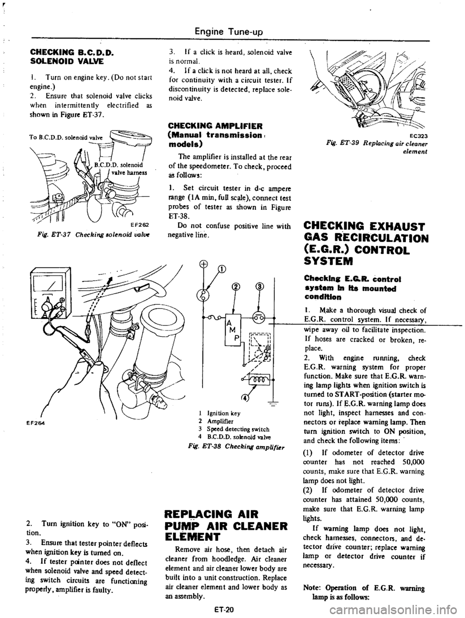
CHECKING
B
C
D
D
SOLENOID
VALVE
I
Turn
on
engine
key
Do
not
start
engine
2
Ensure
that
solenoid
valve
clicks
when
intermittently
electrified
as
shown
in
Figure
ET
37
Fig
ET
37
Checking
solenoid
uolV
l
I
l
EF264
2
Turn
ignition
key
to
ON
posi
tion
3
Ensure
that
tester
pointer
deflects
when
ignition
key
is
turned
on
4
If
tester
panter
does
not
deflect
when
solenoid
valve
and
speed
detect
ing
switch
circuits
are
functioning
properly
amplifier
is
faulty
Engine
Tune
up
3
If
a
click
is
heard
solenoid
valve
is
normal
4
If
a
click
is
not
heard
at
all
check
for
continuity
with
a
circuit
tester
If
discontinuity
is
detected
replace
sole
naid
valve
CHECKING
AMPLIFIER
Manual
transmission
models
The
amplifier
is
installed
at
the
rear
of
the
speedometer
To
check
proceed
as
follows
1
Set
circuit
tester
in
d
c
ampere
range
IA
min
full
scale
connect
test
probes
of
tester
as
shown
in
Figure
ET
38
Do
not
confuse
positive
line
with
negative
line
M
p
1
II
L
o
A
I
of
j
t
J
f
T
1
Ignition
key
2
Amplifier
3
Speed
detecting
switch
4
B
C
D
D
solenoid
valve
Fig
ET
38
Checking
amplifiu
REPLACING
AIR
PUMP
AIR
CLEANER
ELEMENT
Remove
air
hose
then
detach
air
cleaner
from
hoodledge
Air
cleaner
element
and
air
cleaner
lower
body
are
built
into
a
unit
construction
Replace
air
cleaner
element
and
lower
body
as
an
assembly
ET
20
EC323
Fig
ET
39
Repl4cing
air
cleaner
element
CHECKING
EXHAUST
GAS
RECIRCULATION
E
G
R
CONTROL
SYSTEM
Checkln
E
G
R
control
system
In
Ita
mounted
condition
I
M
ake
a
thorough
visual
check
of
E
G
R
control
system
If
necessary
wipe
away
oil
to
facilitate
inspection
If
hoses
are
cracked
or
broken
fe
place
2
With
engine
running
check
E
G
R
warning
system
for
proper
function
Make
sure
that
E
G
R
warn
ing
lamp
light
when
ignition
switch
is
turned
to
START
position
starter
mo
tor
runs
If
E
G
R
warning
lamp
does
not
light
inspect
harnesses
and
con
nectors
or
replace
warning
lamp
Then
turn
ignition
switch
to
ON
position
and
check
the
following
items
I
If
odometer
of
detector
drive
counter
has
not
reached
50
000
counts
make
sure
that
E
G
R
warning
lamp
does
not
light
2
If
odometer
of
detector
drive
counter
has
attained
50
000
counts
make
sure
that
E
G
R
warning
lamp
lights
If
warning
lamp
does
not
light
check
harnesses
connector
and
de
tector
drive
counter
replace
warning
lamp
or
detector
drive
counter
if
necessary
Note
Operation
of
E
G
R
warning
lamp
is
as
follows
Page 33 of 537
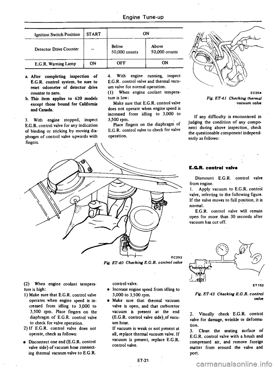
Ignition
Switch
Position
START
Detector
Drive
Counter
E
G
R
Warning
Lamp
ON
a
After
completing
inspection
of
E
G
R
control
system
be
sure
to
reset
odometer
of
detector
drive
counter
to
zero
b
This
item
applies
to
620
models
except
those
bound
for
California
and
Canada
3
With
engine
stopped
inspect
E
G
R
control
valve
for
any
indication
of
binding
or
sticking
by
movirig
dia
phragm
of
control
valve
upwards
with
fmgers
Engine
Tune
up
ON
Below
50
000
counts
Above
50
000
counts
OFF
ON
4
With
engine
running
inspect
E
G
R
control
valve
and
thermal
vacu
um
valve
for
normal
operation
I
When
engine
coolant
tempera
ture
is
low
Make
sure
that
E
G
R
control
valve
does
not
operate
when
engine
speed
is
increased
from
idling
to
3
000
to
3
500
rpm
Place
fingers
on
the
diaphragm
of
E
G
R
control
valve
to
check
for
valve
operation
2
When
engine
coolant
tempera
ture
is
high
I
Make
sure
that
E
G
R
control
valve
operates
when
engine
speed
is
in
creased
from
idling
to
3
000
to
3
500
rpm
Place
fingers
on
the
diaphragm
of
E
G
R
control
valve
to
check
for
valve
operation
2
If
E
G
R
control
valve
does
not
operate
check
as
follows
Disconnect
one
end
E
G
R
control
valve
side
ofvacuum
hose
connect
ing
thermal
vacuum
valve
to
E
G
R
EC253
Fig
ET
40
Checking
E
G
R
control
valve
control
valve
Increase
engine
speed
from
idling
to
3
000
to
3
500
rpm
Make
sure
that
thermal
vacuum
valve
is
open
and
that
carburetor
vacuum
is
present
at
the
end
E
G
R
control
valve
side
ofvacu
urn
hose
If
vacuum
is
weak
or
not
present
at
all
replace
thermal
vacuum
valve
If
vacuum
is
present
replace
E
G
R
con
trol
valve
ET
21
EC254
Fig
ET
41
Checking
thermal
vacuum
valw
If
any
difficulty
is
encountered
in
judging
the
condition
of
any
compo
nent
during
above
inspection
check
the
questionable
component
independ
ently
as
follows
E
G
R
control
valve
Dismount
E
G
R
control
valve
from
engine
I
Apply
vacuum
to
E
G
R
control
valve
referring
to
the
following
figure
If
the
valve
moves
to
full
position
it
is
normal
E
G
R
control
valve
will
remain
open
for
more
than
30
seconds
after
vacuum
has
cut
off
0
r11
hC
J
ET152
Fig
ET
42
Checking
E
G
R
control
VGlve
2
Visually
check
E
G
R
control
valve
for
damage
wrinkle
or
deforma
tion
3
Clean
the
seating
surface
of
E
G
R
control
valve
with
a
brush
and
compressed
air
and
remove
foreign
matter
from
around
the
valve
and
port
Page 34 of 537
r
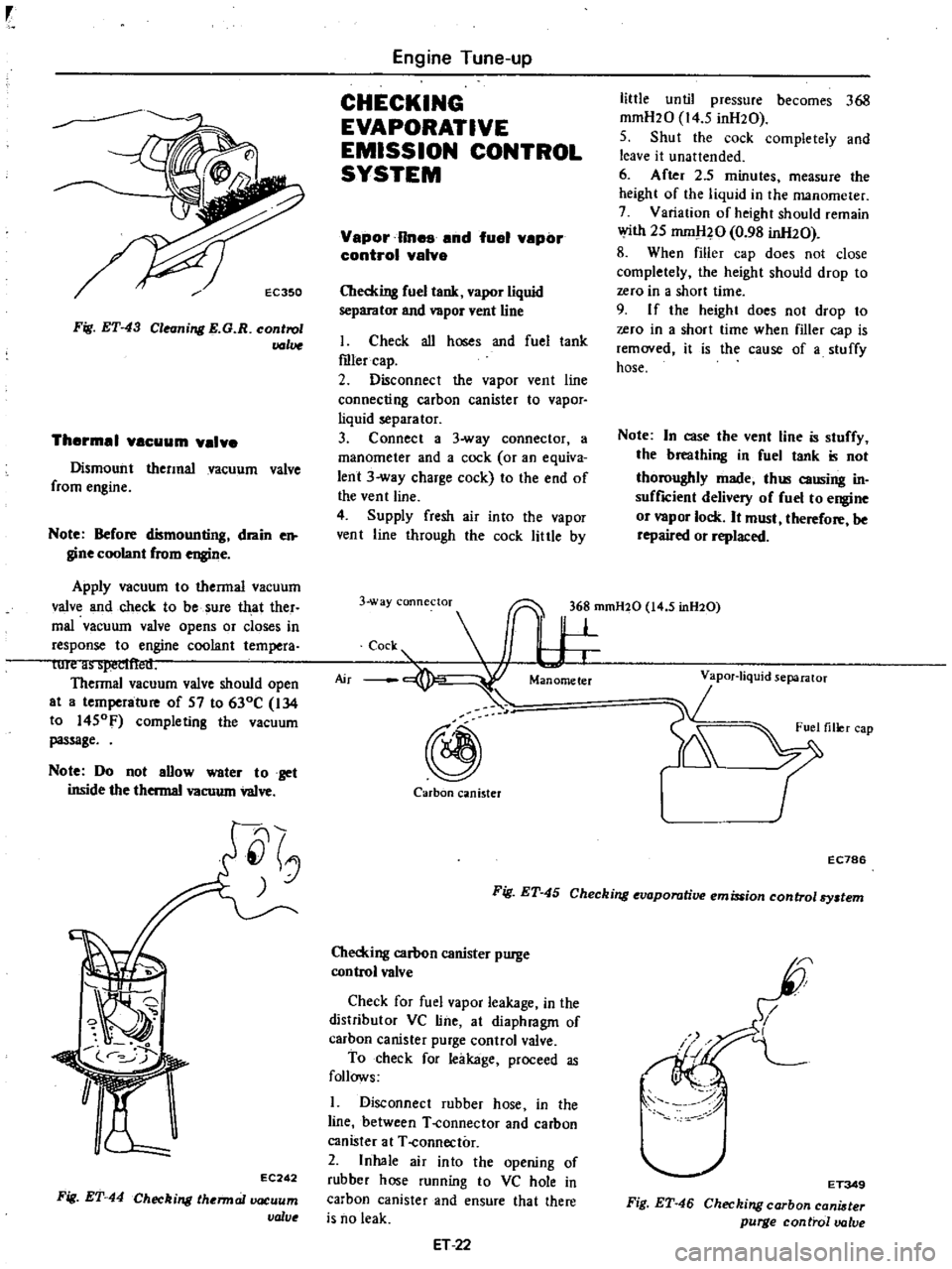
EC350
Fig
ET
43
Cleanill
l
E
G
R
control
lJ
Jlue
Thermal
VBCuum
valve
Dismount
thermal
vacuum
valve
from
engine
Note
Before
dismounting
drain
e
gine
coolant
from
engine
Apply
vacuum
to
thermal
vacuum
valve
and
check
to
be
sure
that
ther
mal
vacuum
valve
opens
or
closes
in
response
to
engine
coolant
tempera
lurt
i1
i
iYCl
lt
lt
U
Thermal
vacuum
valve
should
open
at
a
temperature
of
57
to
630C
134
to
1450F
completing
the
vacuum
passage
Note
Do
not
aUow
water
to
get
inside
the
thermal
vacuum
valve
EC
242
Fig
ET
44
Checkill
lthermallXlCuum
valve
Engine
Tune
up
CHECKING
EVAPORATIVE
EMISSION
CONTROL
SYSTEM
Vapor
Rnes
and
fuel
vepor
control
valve
Checking
fuel
tank
vapor
liquid
separator
and
vapor
vent
line
I
Check
all
hoses
and
fuel
tank
roler
cap
2
Disconnect
the
vapor
vent
line
connecting
carbon
canister
to
vapor
liquid
separator
3
Connect
a
3
way
connector
a
manometer
and
a
cock
or
an
equiva
lent
3
way
charge
cock
to
the
end
of
the
vent
line
4
Supply
fresh
air
into
the
vapor
vent
line
through
the
cock
little
by
little
until
pressure
becomes
368
mmH20
14
5
inH20
5
Shut
the
cock
completely
and
leave
it
unattended
6
After
2
5
minutes
measure
the
height
of
the
liquid
in
the
manometer
7
Variation
of
height
should
remain
with
25
mm
l20
0
98
inH20
8
When
filler
cap
does
not
close
completely
the
height
should
drop
to
zero
in
a
short
time
9
I
f
the
height
does
not
drop
to
zero
in
a
short
time
when
filler
cap
is
removed
it
is
the
cause
of
a
stuffy
hose
Note
In
case
the
vent
line
is
stuffy
the
breathing
in
fuel
tank
is
not
thoroughly
made
thl
causing
in
suffICient
delivery
of
fuel
to
engine
or
vapor
lock
It
must
therefore
be
repaired
or
replaced
3
way
connectoT
36
mmH20
14
5
inH20
c
s
I
W
@
Carbon
canister
r
EC786
Fig
ET
45
Checking
evaporative
emission
control
By
tem
Checking
carbon
canister
purge
control
valve
Check
for
fuel
vapor
leakage
in
the
distributor
VC
line
at
diaphragm
of
carhon
canister
purge
control
valve
To
check
for
leakage
proceed
as
follows
1
Disconnect
rubber
hose
in
the
line
between
T
connector
and
carbon
canister
at
T
connector
2
Inhale
air
into
the
opening
of
rubber
hose
running
to
VC
hole
in
carbon
canister
and
ensure
that
there
is
no
leak
ET
22
I
I
L
I
ET349
Fig
ET
46
Checking
carbon
cani
ter
purge
control
valve
Page 35 of 537
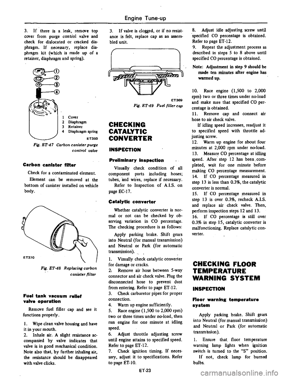
3
If
there
is
a
leak
remove
top
cover
from
purge
contiol
valve
and
check
for
dislocated
or
cmcked
dia
phragm
If
necessary
replace
dia
phmgm
kit
which
is
made
up
of
a
retainer
diaphragm
and
spring
I
@
1
Cover
2
Diaphragm
3
Retainer
4
Diaphragm
spring
Fig
ET
47
ET350
Carbon
caniater
purge
control
valve
Carbon
unlster
filter
Check
for
a
contaminated
element
Element
can
be
removed
at
the
bottom
of
canister
installed
on
vehicle
body
Fig
ET
48
Replacing
carbon
canister
filter
Fuel
tank
vacuum
relief
valve
operation
Remove
fuel
filler
cap
and
see
it
functions
properly
I
Wipe
clean
valve
housing
and
have
it
in
your
mouth
2
Inhale
air
A
slight
resistance
ac
companied
by
valve
indicates
that
valve
is
in
good
mechanical
condition
Note
also
that
by
further
inhaling
air
the
resistance
should
be
disappeared
with
valve
clicks
Engine
Tune
up
3
If
valve
is
clogged
or
if
no
resist
ance
is
felt
replace
cap
as
an
assem
bled
unit
r
u
ET369
Fig
ET
49
Fuel
filler
cap
CHECKING
CATALYTIC
CONVERTER
INSPECTION
Preliminary
inspection
Visually
check
condition
of
all
component
parts
including
hoses
tubes
and
wires
replace
if
necessary
Refer
to
Inspection
of
A
I
S
on
page
EC
17
Catalytic
converter
Whether
catalytic
converter
is
nOf
mal
or
not
can
be
checked
by
ob
serving
variation
in
CO
percentage
The
checking
procedure
is
as
follows
Apply
parking
brake
Shift
gears
into
Neutral
for
manual
transmission
and
Neutral
or
Park
for
automatic
transmission
1
Visually
check
catalytic
converter
for
damage
or
cracks
2
Remove
air
hose
between
5
way
connector
and
air
check
valve
Plug
the
disconnected
hose
to
prevent
dust
from
entering
Refer
to
page
ET
12
3
Check
carburetor
pipes
for
proper
connection
4
Warm
up
engine
sufficiently
5
Race
engine
1
500
to
2
000
rpm
two
or
three
times
under
no
load
then
run
engine
for
one
minute
at
idling
speed
6
Adjust
throttle
adjusting
screw
until
engine
attains
to
specified
speed
Refer
to
page
ET
12
7
Check
ignition
timing
If
neces
sary
adjust
it
to
specifications
Refer
to
page
ET
10
ET
23
8
Adjust
idle
adjusting
screw
until
specified
CO
percentage
is
obtained
Refer
to
page
ET
12
9
Repeat
the
adjustment
process
as
described
in
steps
5
to
8
above
until
specified
CO
percentage
is
obtained
Note
Adjustment
in
step
9
should
be
made
ten
minutes
after
engine
has
warmed
up
10
Race
engine
1
500
to
2
000
rpm
two
or
three
times
under
no
load
and
make
sure
that
specified
CO
per
centage
is
obtained
I
1
Remove
cap
and
connect
air
hose
to
air
check
valve
If
idling
speed
increases
readjust
it
to
specified
speed
with
throttle
ad
justing
screw
12
Warm
up
engine
for
about
four
minutes
at
2
000
rpm
under
n
load
13
Measure
CO
percentage
at
idling
speed
After
step
12
has
been
com
pleted
wait
for
one
minute
before
making
CO
percentage
measurement
14
If
CO
percentage
measured
in
step
13
is
less
than
0
3
the
catalylic
converter
is
normal
15
If
CO
percentage
measured
in
step
13
is
over
0
3
recheck
A
I
S
and
replace
air
check
valve
Then
perform
inspection
steps
12
and
13
16
If
CO
percentage
is
still
over
0
3
in
step
15
catalytic
converter
is
malfunctioning
Replace
catalytic
con
verter
CHECKING
FLOOR
TEMPERATURE
WARNING
SYSTEM
INSPECTION
Floor
warning
temperature
system
Apply
parldng
brake
Shift
gears
into
Neutral
for
manual
transmission
and
Neutral
or
Park
for
automatic
transmission
1
Ensure
that
floor
tern
perature
warning
lamp
lights
when
ignition
switch
is
turned
to
the
S
position
If
not
check
lamp
for
burned
bul
bs
Page 36 of 537
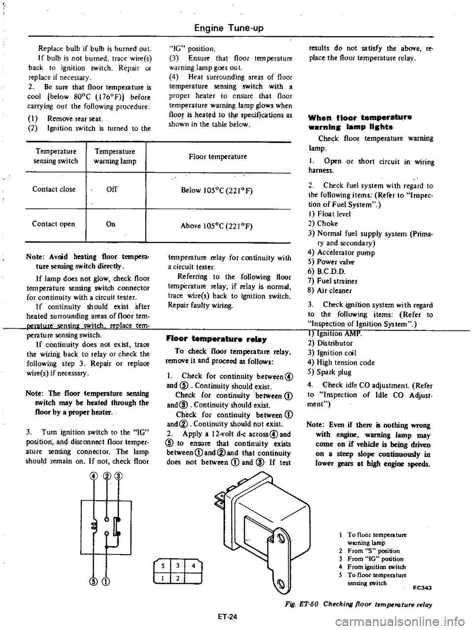
Replace
bulb
if
bulb
is
burned
ou
t
If
bulb
is
not
burned
trace
wireis
back
to
ignition
switch
Repair
or
replace
if
necessary
2
Be
sure
that
floor
temperature
is
cool
below
800C
1760F
before
carrying
out
the
following
procedure
1
Remove
rear
seat
2
Ignition
switch
is
turned
to
the
Temperature
sensing
switch
Temperature
warning
lamp
Contact
close
Off
Contact
open
On
Note
Avoid
heating
floor
tempera
ture
sensing
switch
directly
If
lamp
does
not
glow
check
floor
temperature
sensing
switch
connector
for
continuity
with
a
circuit
tester
If
continuity
should
exist
after
heated
surrounding
areas
of
floor
tern
rv
wnTP
sen
cinq
S
Vitch
reolace
tem
perature
sensing
switch
If
continuity
does
not
exist
trace
the
wiring
back
to
relay
or
check
the
following
step
3
Repair
or
replace
wire
s
if
necessary
Note
The
floor
temperature
sensing
switch
may
be
heated
through
the
floor
by
a
proper
heater
3
Turn
ignition
switch
to
the
IG
position
anf
disconnect
floor
temper
ature
sensing
connector
The
lamp
should
remain
on
If
not
check
floor
4
0
3
UJ
GJO
Engine
Tune
up
IGU
position
3
Ensure
that
floor
tem
perature
warning
lamp
goes
out
4
Heat
surrounding
areas
of
floor
temperature
sensing
switch
with
a
proper
heater
to
ensure
that
floor
temperature
warning
lamp
glows
when
floor
is
heated
to
lh
specifications
as
shown
in
the
table
below
Floor
temperature
Below
1050C
22IOF
Above
1050C
2210F
temperature
relay
for
continuity
with
a
circuit
tester
Referring
to
the
following
floor
temperature
relay
if
relay
is
normal
trace
wire
s
back
to
ignition
switch
Repair
faulty
wiring
Floor
temperature
rela
To
check
floor
temperature
relay
remove
it
and
proceed
as
follows
1
Check
for
continuity
between@
and
@
Continuity
should
exist
Check
for
continuity
between
D
and@
Continuity
should
exist
Check
for
continuity
between
D
and@
Continuity
should
not
exist
2
Apply
a
12
volt
doC
across@and
@
to
ensure
that
continuity
exists
between
D
and@and
that
continuity
does
not
between
D
and
@
If
test
r
I
141
ET
24
results
do
not
satisfy
the
above
reo
place
the
floor
temperature
relay
When
floor
temperature
warnln8
lamp
118hts
Check
floor
temperature
warning
lamp
I
Open
or
short
circuit
in
wiring
harness
2
Check
fuel
system
with
regard
to
the
following
items
Refer
to
Inspec
tion
of
Fuel
System
I
Floa
t
level
2
Choke
3
Normal
fuel
supply
system
Prima
ry
and
secondary
4
Accelerator
pump
5
Power
valve
6
B
C
D
D
7
Fuel
strainer
8
Air
cleaner
3
Check
ignition
system
with
regard
to
the
following
items
Refer
to
Inspection
of
Ignition
System
I
IgnItion
AMI
2
Distributor
3
Ignition
coil
4
High
tension
code
5
Spark
plug
4
Check
idle
CO
adjustment
Refer
to
Inspection
of
Idle
CO
Adjust
roeoC
Note
Even
if
there
is
nothing
wrong
with
engine
warning
lamp
may
come
on
if
vehicle
is
being
driven
on
a
steep
slope
continuously
in
lower
gears
at
high
engine
speeds
To
floor
temperature
warning
lamp
2
From
S
position
3
From
GOt
position
4
From
ignition
switch
5
To
floor
temperature
sensing
switch
EC343
Fig
ET
50
Checking
floor
temperature
relay
Page 37 of 537
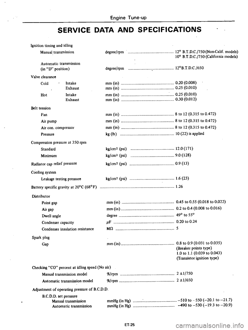
Engine
Tune
up
SERVICE
DATA
AND
SPECIFICATIONS
Ignition
timing
and
idling
Manual
transmission
Automatic
transmission
in
D
position
Valve
clearance
Cold
Intake
Exhaust
Intake
Exhaust
Hot
Belt
tension
Fan
Air
pump
Air
coo
compressor
Pressure
Compression
pressure
at
350
rpm
Standard
Minimum
Radiator
cap
relief
pressure
Cooling
system
Leakage
testing
pressure
Battery
specific
gravity
at
200C
680F
Distribu
tor
Point
gap
Air
gap
Dwell
angle
Condenser
capacity
Condenser
insulation
resistance
Spark
plug
Gap
degree
rpm
120
B
T
D
C
j750
Non
Calif
models
100
B
T
D
C
j750
California
models
degree
rpm
l20B
T
D
C
j650
mm
in
mm
in
mm
in
mm
in
0
20
0
008
0
25
0
010
0
25
0
010
0
30
0
012
mm
in
mm
in
mm
in
kg
lb
8
to
12
0
315
to
0
472
8to
12
0
315
to
0
472
8
to
12
0
315
to
0
472
10
22
is
applied
kg
cm2
psi
kg
em2
psi
kg
em
2
psi
12
0
171
9
0
128
0
9
13
kg
cm2
Psi
1
6
23
1
26
mm
in
mm
in
degree
IF
Mil
0
45
to
0
55
0
018
to
0
022
0
2
to
0
4
0
008
to
0
016
490
to
550
0
20
to
0
24
5
mm
in
0
8
to
0
9
0
031
to
0
035
Breaker
points
type
1
0
to
1
1
0
039
to
0
043
Transistor
ignition
type
Checking
CO
percent
at
idling
speed
No
air
Manual
transmission
model
rpm
Automatic
transmission
model
rpm
Adjustment
of
operating
pressure
of
B
C
D
D
B
C
D
D
set
pressure
Manual
transmission
Automatic
transmission
2
1
1
750
2
1
1
650
mmHg
in
Hg
mmHg
in
Hg
510
to
550
20
1
to
21
7
490
to
530
19
3
to
20
9
ET
25