ECU DATSUN PICK-UP 1977 Owner's Manual
[x] Cancel search | Manufacturer: DATSUN, Model Year: 1977, Model line: PICK-UP, Model: DATSUN PICK-UP 1977Pages: 537, PDF Size: 35.48 MB
Page 150 of 537
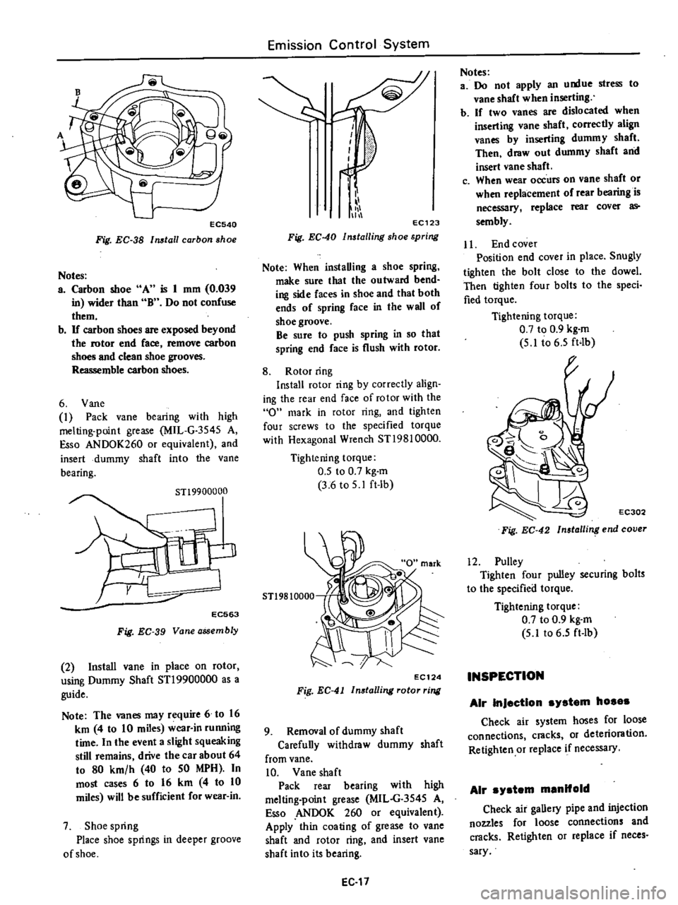
EC540
Fig
EC
38
Install
carbon
shoe
Notes
a
Carbon
shoe
A
is
1
mm
0
039
in
wider
than
B
Do
not
confuse
them
b
If
carbon
shoes
are
exposed
beyond
the
rotor
end
face
remove
carbon
shoes
and
clean
shoe
grooves
Reassemble
carbon
shoes
6
Vane
1
Pack
vane
bearing
with
high
melting
point
grease
MIL
G
3545
A
Esso
ANDOK260
or
equivalent
and
insert
dummy
shaft
into
the
Vane
bearing
STl9900000
EC563
Fig
EC
39
Vane
assembly
2
Install
vane
in
place
on
rotor
using
Dummy
Shaft
STl9900000
as
a
guide
Note
The
vanes
may
require
6
to
16
km
4
to
10
miles
wear
in
running
time
In
the
event
a
slight
squeaking
still
remains
drive
the
car
about
64
to
80
km
h
40
to
50
MPH
In
most
cases
6
to
16
km
4
to
10
miles
will
be
sufficient
for
wear
in
7
Shoe
spring
Place
shoe
springs
in
deeper
groove
of
shoe
Emission
Control
System
i
111
11
EC123
Fig
EC
40
Installing
shoe
spring
Note
When
instaUing
a
shoe
spring
make
sure
that
the
outward
bend
ing
side
faces
in
shoe
and
that
both
ends
of
spring
face
in
the
wall
of
shoe
groove
Be
sure
to
push
spring
in
so
that
spring
end
face
is
flush
with
rotor
8
Rotor
ring
Install
rotor
ring
by
correctly
align
ing
the
rear
end
face
of
rotor
with
the
0
mark
in
rotor
ring
and
tighten
four
screws
to
the
specified
torque
with
Hexagonal
Wrench
ST19810000
Tightening
torque
0
5
to
0
7
kg
m
3
6
to
5
1
ft
lb
5T19810000
EC124
Fig
EC
41
In8talling
rotor
ring
9
Removal
of
dummy
shaft
Carefuny
withdraw
dummy
shaft
from
vane
10
Vane
shaft
Pack
rear
bearing
with
high
melting
point
grease
MIL
G
3545
A
so
ANDOK
260
or
equivalent
Apply
thin
coating
of
grease
to
vane
shaft
and
rotor
ring
and
insert
vane
shaft
into
its
bearing
EC
17
Notes
a
Do
not
apply
an
u
tue
stress
to
vane
shaft
when
inserting
b
If
two
vanes
are
dislocated
when
inserting
vane
shaft
correctly
align
vanes
by
inserting
dummy
shaft
Then
draw
out
dummy
shaft
and
insert
vane
shaft
c
When
wear
occurs
on
vane
shaft
or
when
replacement
of
rear
bearing
is
necessary
replace
rear
cover
as
sembly
Jl
End
cover
Position
end
cover
in
place
Snugly
tighten
the
bolt
close
to
the
dowel
Then
tighten
four
bolts
to
the
speci
fied
torque
Tightening
torque
0
7
to
0
9
kg
m
5
1
t06
5
ft4b
EC302
Fig
EC
42
Insla
ling
end
cover
12
Pulley
Tighten
four
pulley
securing
bolts
to
the
specified
torque
Tightening
torque
0
7
to
0
9
kg
m
5
lt06
5
ft
lb
INSPECTION
Air
InJection
system
hosas
Check
air
system
hoses
for
loose
connections
cracks
or
deterioration
Retighten
or
replace
if
necessary
Air
ystem
manifold
Check
air
gaUery
pipe
and
injection
nozzles
for
loose
connections
and
cracks
Retighten
or
replace
if
neces
sary
Page 151 of 537

Air
pump
I
Operate
engine
until
it
reaches
normal
operating
temperature
2
Inspect
all
hose
hose
connec
tions
and
air
gallery
for
leaks
and
correct
if
necessary
before
checking
air
injection
pump
3
Check
air
injection
pump
belt
tension
and
adjust
to
specifications
if
necessary
4
Disconnect
air
supply
hose
at
check
valve
5
Disconnect
vacuum
hose
from
the
air
control
valve
California
type
only
6
Insert
open
pipe
end
of
Air
Pump
Test
Gauge
Adapter
STl9870000
in
air
supply
hose
Clamp
hose
securely
to
adapter
to
prevent
it
from
blowing
out
Position
adapter
and
test
lli
uge
so
that
air
blast
emitted
through
drilled
pipe
plug
will
be
harmlessly
dissipated
7
Install
a
tachometer
on
engine
With
engine
speed
at
2
600
rpm
ob
serve
pressure
produced
at
test
gauge
Air
pressure
should
be
100
mmHg
3
94
inHg
or
more
8
If
air
pressure
does
not
meet
above
specifications
proceed
as
fol
lows
I
Repeat
2
and
3
above
2
Disconnect
air
supply
hose
at
anti
backfire
valve
Plug
air
hose
open
ing
and
screw
with
a
clamp
Repeat
pressure
test
3
With
engine
speed
at
1
500
rpm
close
hole
of
test
gauge
with
finger
If
a
leaking
sound
is
heard
or
leaking
air
is
felt
by
ftnger
at
relief
valve
relief
valve
is
malfunctioning
Relief
valve
should
be
replaced
or
repaired
4
If
air
injection
pump
does
not
meet
minimum
requirement
of
pres
sure
test
it
should
be
replaced
Control
valve
The
following
procedures
are
reo
commended
for
checking
and
or
as
certaining
that
the
various
components
of
the
exhaust
emission
con
Irol
system
are
operating
properly
The
engine
and
all
components
must
be
at
normal
operating
tempera
tures
when
the
tests
are
performed
Prior
to
performing
any
extensive
diag
nosis
of
the
exhaust
control
system
it
Emission
Control
System
must
be
determined
that
the
engine
as
a
unit
is
functioning
properly
Check
valva
Warm
up
engine
thoroughly
2
Disconnect
hose
leading
to
check
valve
from
air
hose
COJUlector
3
Check
hose
opening
for
any
indi
cation
of
exhaust
gas
leaks
Ifleaks
are
detected
replace
check
valve
4
Race
the
engine
lightly
at
about
2
000
cpm
and
then
return
it
to
idling
VisuaDy
check
the
hose
for
any
indication
of
exhaust
gas
leaks
before
the
engine
returns
to
idling
speed
If
leaks
are
detected
replace
check
valve
EC310
Fig
EC
43
Checking
check
valve
Air
pump
raIle
valve
After
completing
inspection
of
air
pump
check
air
pump
relief
valve
in
the
following
steps
J
Disconnect
hoses
leading
to
check
valve
and
air
control
valve
from
air
hose
connector
and
install
blind
cap
to
the
connector
2
With
engine
running
at
about
3
000
rpm
under
no
load
place
your
hand
on
the
air
outlet
of
air
pump
relief
valve
to
check
for
discharged
air
If
no
air
is
felt
replace
the
air
pump
relief
valve
EC311
Fig
EC
44
Checking
air
pump
relief
valve
EC
18
Air
control
valve
C
U
ornla
models
I
Warm
up
engine
thoroughly
2
Before
checking
air
control
valve
check
all
hoses
for
loose
connection
leaks
etc
and
repair
or
correct
if
necessary
3
With
engine
idling
disconnect
the
outlet
side
hose
of
the
air
control
valve
and
place
your
hand
on
the
air
hose
outlet
to
check
for
air
If
no
air
is
felt
replace
the
air
control
valve
4
Pull
vacuum
hose
off
from
air
con
trol
valve
If
discharge
of
air
from
air
hose
stops
the
air
con
trol
valve
is
normaL
If
discharge
is
still
felt
replace
the
valve
Plug
up
the
removed
vacuum
hose
to
stabilize
engine
running
EC312
Fig
EC
45
Checking
air
control
valve
Emarsancy
air
rella
valve
E
A
R
Valve
lCalHornla
models
L
Warm
up
engine
thoroughly
2
Before
checking
air
control
valve
check
all
hoses
for
loose
connection
leaks
etc
and
repair
or
correct
if
necessary
3
Race
engine
approximately
2
000
rpm
under
no
load
Place
your
hand
on
air
outlet
of
E
A
R
valve
to
check
for
presence
of
discharged
air
If
no
air
is
felt
E
A
R
valve
is
normal
4
Disconnect
vacuum
hose
from
B
A
R
valve
as
shown
in
Figure
EC
46
Page 157 of 537
4
E
G
R
warning
system
EC251
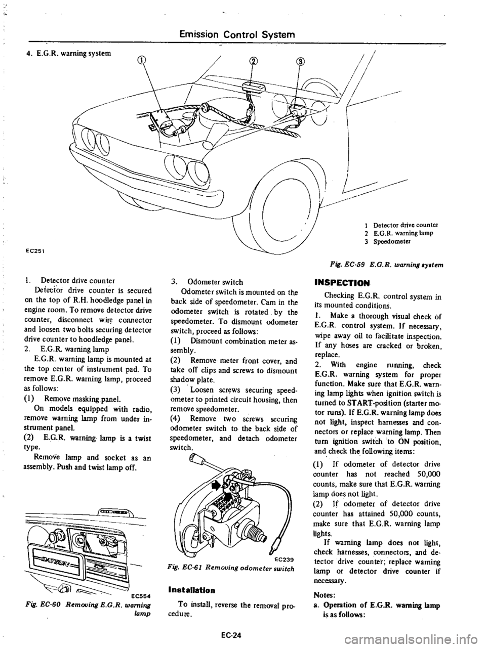
Detector
drive
counter
Detecfor
drive
counter
is
secured
on
the
top
of
R
H
hoodledge
panel
in
engine
room
To
remove
detector
drive
counter
disconnect
w
COJUlector
and
loosen
two
bolts
securing
detector
drive
counter
to
hoodledge
panel
2
E
G
R
warning
lamp
E
G
R
warning
lamp
is
mounted
at
the
top
cen
ter
of
instrument
pad
To
remove
E
G
R
warning
lamp
proceed
as
follows
1
Remove
masking
panel
On
models
equipped
with
radio
remove
warning
lamp
from
under
in
strument
panel
2
E
G
R
warning
lamp
is
a
twist
type
Remove
lamp
and
socket
as
an
assembly
Push
and
twist
lamp
off
can
EC554
Fig
EC
60
Removing
E
G
R
warning
lamp
Emission
Control
System
3
Odometer
switch
Odometer
switch
is
mounted
on
the
back
side
of
speedometer
Cam
in
the
odometer
switch
is
rotated
by
the
speedometer
To
dismount
odometer
switch
proceed
as
follows
I
Dismount
combination
meter
as
sembly
2
Remove
meter
front
cover
and
take
off
clips
and
screws
to
dismount
shadow
plate
3
Loosen
screws
securing
speed
ometer
to
printed
circuit
housing
then
remove
speedometer
4
Remove
two
screws
securing
odomete
switch
to
the
back
side
of
speedometer
and
detach
odometer
switch
EC239
Fig
EC
61
Removing
odometer
switch
InstaUatlon
To
install
reverse
the
removal
pro
cedure
EC24
V
r
CID
1
Detector
drive
counter
2
E
G
R
warning
lamp
3
Speedometer
Fig
EC
59
E
G
R
warning
y
tem
INSPECTION
Checking
E
G
R
control
system
in
its
mounted
conditionS
I
Make
a
thorough
visual
check
of
E
G
R
control
system
If
necessary
wipe
away
oil
to
facilitate
inspection
If
any
hoses
are
cracked
or
broken
replace
2
With
engine
running
check
E
G
R
warning
system
for
proper
function
Make
sure
that
E
G
R
warn
ing
lamp
lights
when
ignition
switch
is
turned
to
START
position
starter
mo
tor
runs
If
E
G
R
wanung
lamp
does
not
light
inspect
harnesses
and
con
nectors
or
replace
warning
lamp
Then
turn
ignition
switch
to
ON
position
and
check
the
following
items
I
If
odometer
of
detector
drive
counter
has
not
reached
50
000
counts
make
sure
that
E
G
R
warning
lamp
does
not
light
2
If
odomete
of
detector
drive
counter
has
attained
50
000
counts
make
sure
that
E
G
R
warning
lamp
lights
If
warning
lamp
does
not
light
check
harnesses
connectors
and
de
tector
drive
counter
replace
warning
lamp
or
detector
drive
counter
if
necessary
Notes
Operation
oC
E
G
R
warning
lamp
is
as
Collows
Page 170 of 537

BATTERY
FREEZING
Battery
electrolyte
freezing
point
varies
with
acid
concentration
or
its
specific
gravity
A
battery
with
an
insufficient
charge
will
freeze
at
lower
temperatures
If
specific
gravity
of
a
battery
falls
below
1
1
this
is
an
0
10
20
30
g
40
I
u
il
SO
I
0
e
60
0
E
70
Engine
Electrical
System
indication
that
battery
is
completely
discharged
and
will
freeze
readily
when
temperatures
fall
below
freezing
Note
Use
extreme
caution
to
avoid
freezing
battery
since
freezing
will
generally
ruin
the
battery
1
80
1
00
1
04
1
08
t
l2
1
16
t
20
1
24
1
28
Specific
gravity
of
electrolyte
CHARGING
I
f
electrolyte
level
is
satisfactory
battery
must
be
charged
when
electro
lyte
gravity
reading
falls
below
1
20
If
battery
on
car
is
quick
charged
to
1
32
EEOQ4
Fig
EE
4
Froezing
point
of
electrolyte
bring
it
up
to
full
charge
the
opera
tion
should
be
carried
out
with
nega
tive
cable
removed
Prior
to
charging
corroded
termi
EE
3
nals
should
be
cleaned
with
a
brush
and
common
baking
soda
solution
In
addition
the
following
items
should
be
observed
while
battery
is
being
charged
I
Be
sure
that
electrolyte
level
is
above
top
of
each
plate
2
Keep
removed
plugs
in
a
safe
place
3
Do
not
allow
electrolyte
tempera
ture
to
go
over
450C
I130F
4
After
charging
check
to
be
cer
tain
that
specific
gravity
does
not
exceed
1
260
at
200C
680P
Cor
rection
can
be
made
by
adding
dis
tilled
water
into
cells
as
necessary
5
Keep
battery
away
from
open
flame
while
it
is
being
charged
6
After
all
vent
plugs
have
been
tightened
clean
all
sprayed
electrolyte
off
upper
face
of
battery
INSTALLATION
1
Install
and
tighten
clamps
secure
Iy
2
After
clamps
have
been
tightened
clean
battery
cable
terminals
and
apply
grease
to
retard
formation
of
corrosion
Page 173 of 537
OPERATION
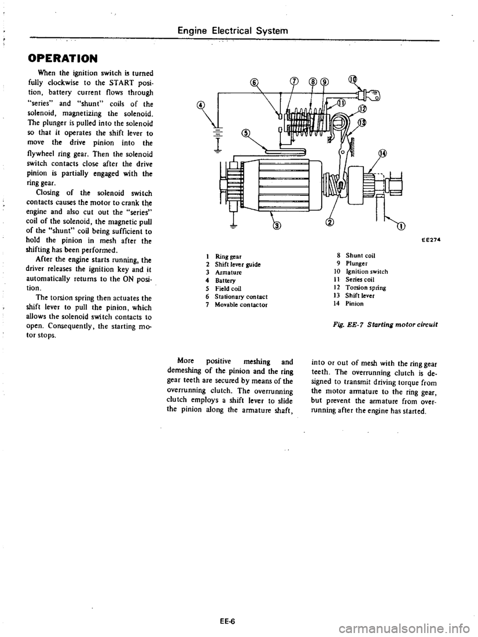
When
the
ignition
switch
turned
fully
clockwise
to
the
START
posi
tion
battery
current
flows
through
series
and
shunt
coils
of
the
solenoid
magnetizing
the
solenoid
The
plunger
is
pulled
into
the
solenoid
so
that
it
operates
the
shift
lever
to
move
the
drive
pinion
into
the
flywheel
ring
gear
Then
the
solenoid
switch
contacts
close
after
the
drive
pinion
is
partially
engaged
with
the
ring
gear
Closing
of
the
solenoid
switch
contacts
c
uses
the
motor
to
crank
the
engine
and
also
cut
out
the
series
coil
of
the
solenoid
the
magnetic
pull
of
the
shunt
coil
being
sufficient
to
hold
the
pinion
in
mesh
after
the
shifting
has
been
performed
After
the
engine
starts
running
the
driver
releases
the
ignition
key
and
it
automatically
returns
to
the
ON
posi
tion
The
torsion
spring
then
actuates
the
shift
lever
to
pull
the
pinion
which
allows
the
solenoid
swi
tch
contacts
to
open
Consequently
the
starting
mo
tor
stops
Engine
Electrical
System
I
I
Ring
gear
2
Shift
lever
guide
3
Armature
4
Battery
5
Field
coil
6
Stationary
contact
7
Monble
contactor
More
positive
meshing
and
demeshing
of
the
pinion
and
the
ring
gear
teeth
are
secured
by
means
of
the
overrunning
clutch
The
overruIUling
clutch
employs
a
shift
lever
to
slide
the
pinion
along
the
armature
shaft
EE
6
F
l
cp
o
r
1
I
I
W
m
EE274
8
Shunt
coil
9
Plunger
10
Ignition
switch
11
Series
coil
12
Torsion
spring
13
Shift
lever
14
Pinion
Fig
EE
7
Starting
motor
circuit
into
or
out
of
mesh
with
the
ring
gear
teeth
The
overrunning
clutch
is
de
signed
to
transmit
driving
torque
from
the
motor
armature
to
the
ring
gear
but
prevent
the
armature
from
over
running
after
the
engine
has
started
Page 174 of 537
CONSTRUCTION
O
o
8
w
il
Engine
Electrical
System
V
1
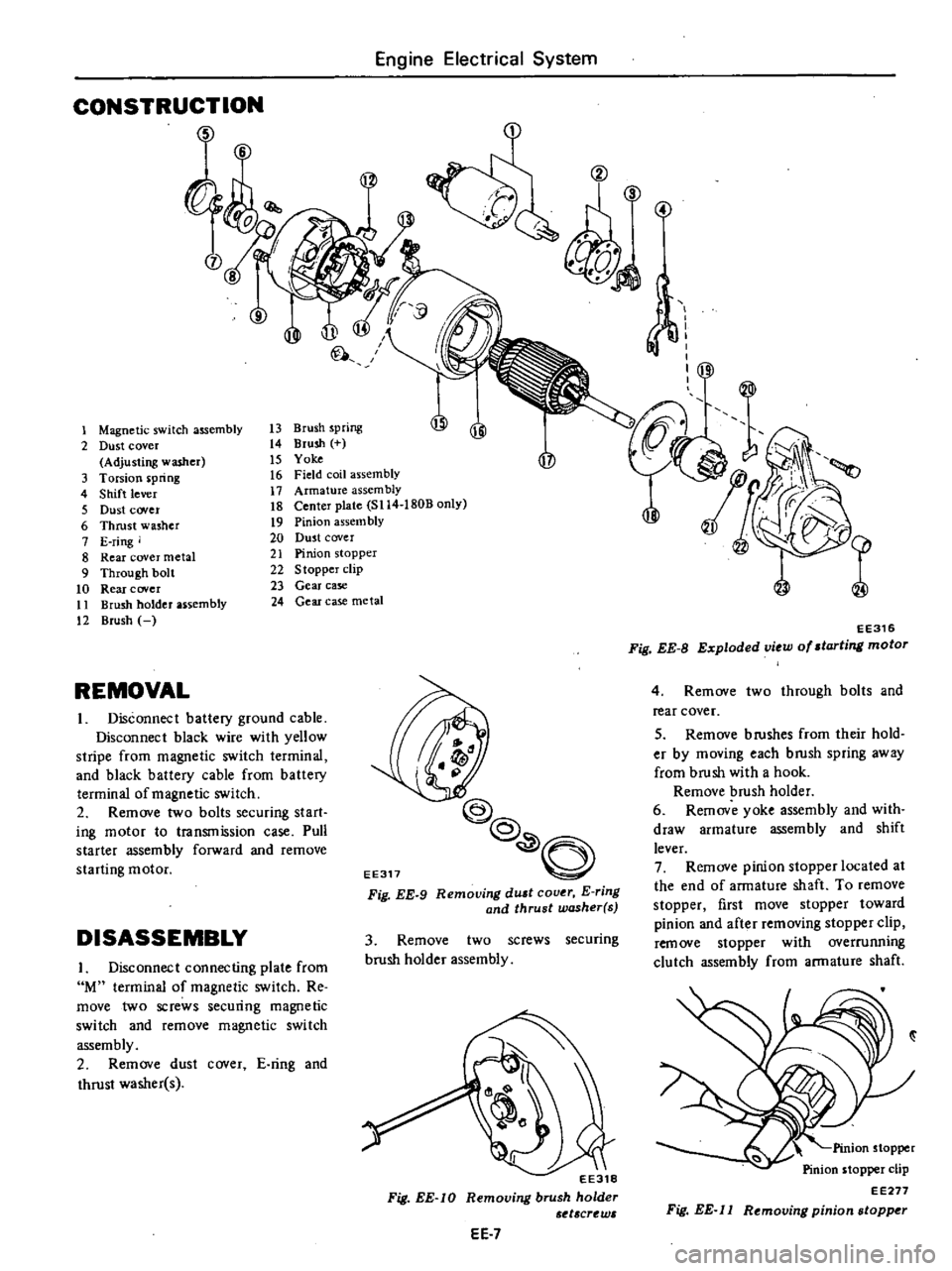
Magnetic
switch
assembly
13
Brush
spring
jj
JI
2
Dust
cover
t4
Brush
Adjusting
washer
15
Yoke
P
3
Torsion
pring
t6
Field
coil
assembly
4
Shift
lever
17
Armature
assembly
5
Dust
cover
18
Center
plate
SI14
1808
only
6
Thrust
washer
19
Pinion
assem
bly
7
E
ring
20
Dust
cover
8
Rear
cover
metal
21
Pinion
stopper
9
Through
bolt
22
Stopper
clip
10
Rear
cover
23
Gear
case
tl
Brush
holder
assembly
24
Gear
case
metal
12
Brush
REMOVAL
Disconnect
battery
ground
cable
Disconnect
black
wire
with
yellow
stripe
from
magnetic
switch
terminal
and
black
battery
cable
from
battery
terminal
of
magnetic
switch
2
Remove
two
bolts
securing
start
ing
motor
to
transmission
case
Pull
starter
assembly
forward
and
remove
starting
motor
DISASSEMBLY
I
Disconnect
connecting
plate
from
M
terminal
of
magnetic
switch
Re
move
two
screws
securing
magnetic
switch
and
remove
magnetic
switch
assembly
2
Remove
dust
cover
E
ring
and
thrust
washer
s
EE317
@
@
O
Fig
EE
9
Remouing
dUlt
cover
E
ring
and
thrust
washer
s
3
Remove
two
screws
securing
brush
holder
assembly
EE318
Fig
EE
IO
Removing
brush
holder
d
crt
w
EE
7
S
4
f
I
jl
I
EE316
Fig
EE
B
Exploded
view
of
starting
motor
4
Remove
two
through
bolts
and
rear
cover
5
Remove
b
rushes
from
their
hold
er
by
moving
each
brush
spring
away
from
brush
with
a
hook
Remove
brush
holder
6
Remov
yoke
assembly
and
with
draw
armature
assembly
and
shift
lever
7
Remove
pinion
stopper
located
at
the
end
of
armature
shaft
To
remove
stopper
first
move
stopper
toward
pinion
and
after
removing
stopper
clip
remove
stopper
with
overrunning
clutch
assembly
from
armature
shaft
Pinion
stopper
Pinion
stopper
clip
EE277
Fig
EE
l1
Removing
pinion
stopper
Page 178 of 537

Engine
Electrical
System
SERVICE
DATA
AND
SPECIFICATIONS
Type
System
voltage
No
load
Terminal
voltage
Current
Revolution
v
V
A
rpm
Brush
length
Outer
diameter
of
commutator
mm
in
mm
in
Brush
spring
tension
kg
Ib
Clearance
between
bearing
metal
and
armature
shaft
mm
in
Clearance
L
between
pinion
front
edge
and
pinion
stopper
mm
in
TROUBLE
DIAGNOSES
AND
CORRECTIONS
Condition
Starting
motor
will
not
operate
Noisy
starting
motor
Starting
motor
cranks
slowly
Probable
cause
Discharged
battery
Damaged
solenoid
switch
Loose
connections
of
terminal
Damaged
brushes
Starti
g
motor
inoperative
Loose
securing
bolt
Worn
pinion
gear
Poor
lubrication
Worn
commutator
Worn
brushes
Discharged
battery
Loose
connection
of
terminal
Worn
brushes
Locked
brushes
EE
ll
Manual
transmission
Automatic
transmission
Optional
for
manual
transmission
SII4
ISOB
S114
170B
12
12
Less
than
60
More
than
7
000
More
than
6
000
More
than
39
1
54
More
than
12
0
47
1
4
to
I
S
3
1
to
4
0
Less
than
0
2
O
OOS
0
3
to
1
5
0
012
to
0
059
Corrective
action
Charge
or
replace
battery
Repair
or
replace
solenoid
switch
Clean
and
tighten
terminal
Replace
brushes
Remove
starting
motor
and
make
test
Tighten
Replace
Add
oil
Replace
Replace
Charge
Clean
and
tighten
Replace
Inspect
brush
spring
tension
or
repair
brush
holder
Page 190 of 537
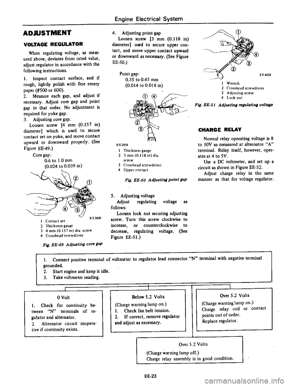
ADJUSTMENT
VOLTAGE
REGULATOR
When
regulating
voltage
as
meas
ured
above
deviates
from
rated
value
adjust
regulator
in
accordance
with
the
following
instructions
I
Inspect
contact
surface
and
if
rough
lightly
polish
with
fine
emery
paper
1
500
or
600
2
Measure
each
gap
and
adjust
if
necessary
Adjust
core
gap
and
point
gap
in
that
order
No
adjustment
is
required
for
yoke
gap
3
Adjusting
core
gap
Loosen
screw
4
mm
0
157
in
diameter
which
is
used
to
secure
contact
set
on
yoke
and
move
contact
upward
or
downward
properly
See
Figure
EE
49
Core
gap
0
6
to
1
0
mm
0
024
to
0
039
in
EE398
I
Contact
set
2
ThicknesJ
gauge
3
4
mm
0
157
in
dia
screw
4
Crosshead
Jcrewdriver
Fig
EE
49
AdjUJJting
core
gap
Engine
Electrical
System
4
Adjusting
point
gap
Loosen
screw
3
mm
O
lIS
in
diameter
used
to
secure
upper
con
tact
and
move
upper
contact
upward
or
downward
as
necessary
See
Figure
EE
50
Point
gap
035
to
0
45
mm
0
014
to
O
D1S
in
EE399
I
Thicknes
gauge
2
3
mm
0
118
in
dia
screw
3
Cro
Sshelld
screwdriver
4
Upper
contact
Fig
EE
50
Adjusting
point
gap
5
Adjusting
voltage
Adjust
regulating
voltage
as
follows
Loosen
lock
nut
securing
adjusting
screw
Turn
this
screw
clockwise
to
increase
or
counterclockwise
to
decrease
regulating
voltage
See
Figure
EE
5
J
CD
EE400
I
Wrench
2
Crosshead
screwdriver
3
Adjusting
screw
4
l
ock
nut
Fig
EE
51
AdjUJJting
rel
Ulating
voltage
CHARGE
RELAY
Nonna
relay
operating
voltage
is
S
to
IOV
as
measured
at
alternator
A
tenninal
Relay
itself
however
oper
ates
at
4
to
5V
Use
a
DC
voltmeter
and
set
up
a
circuit
as
shown
in
Figure
EE
52
Adjust
charge
relay
in
the
same
manner
as
that
for
voltage
regulator
L
Connect
positive
tenninal
of
voltmeter
to
regulator
lead
connector
N
tenninal
with
negative
terminal
grounded
2
Start
engine
and
keep
it
idle
3
Take
voltmeter
reading
o
Volt
I
Check
for
continuity
be
tween
terminals
of
re
gulator
and
alternator
2
Alternator
circuit
inopera
tive
if
continuity
exists
Below
5
2
Volts
Charge
warning
lamp
on
I
Check
fan
belt
tension
2
If
correct
remove
regulator
and
adjust
as
necessary
Over
5
2
Volts
Charge
warning
lamp
on
Charge
relay
coil
or
contact
points
out
of
order
Replace
regulator
Over
5
2
Volts
Charge
warning
lamp
off
Charge
relay
assembly
is
in
good
condition
EE
23
Page 201 of 537

t3
l
l
J
@
r
9
V
fW
@
@
CHECKING
AND
ADJUSTMENT
CAP
AND
ROTOR
HEAD
Cap
and
rotor
head
must
be
in
spected
periodically
as
specified
in
the
Maintenance
Schedule
Remove
cap
and
clean
all
dust
and
carbon
deposits
from
cap
and
rotor
from
time
to
time
If
cap
is
cracked
or
is
leaking
replace
with
a
new
one
AIR
GAP
Standard
air
gap
is
0
2
to
0
4
mm
0
008
to
0
016
in
If
the
gap
is
off
the
standard
adjustment
mould
be
made
by
loos
ening
pick
up
coil
screws
Gap
gauge
is
required
for
adjust
ment
Air
gaps
must
be
checked
from
time
to
time
Air
gap
0
2
to
0
4
mm
0
008
to
0
016
in
Engine
Electrical
System
tl
@
9
EE328
Fig
EE
67
Checking
oir
gap
To
remove
pick
up
cail
disconnect
distributor
harness
at
terminal
block
and
remove
screw
securing
pick
up
coil
ADVANCE
MECHANISMS
Specifications
Type
Item
Vacuum
advance
Distributor
degrees
Distributor
mmHg
inHg
Centrifugal
advance
Distributor
degrees
Distributor
cpm
EE34
1
Cap
assembly
2
Rotor
head
a55embly
3
Roll
pin
4
ReJuctor
S
Pick
up
coil
6
Contactoi
7
Breaker
plate
assembly
8
Packing
9
Rotor
shaft
10
Governor
spring
11
Governor
weigh
t
12
Shaft
a
Jscmbly
13
Cap
setter
14
Vacuum
controller
15
Housing
16
Fixing
plate
17
O
ring
18
Collar
EE327
Fig
EE
66
Exploded
view
of
di3tributor
assembly
and
distributor
harness
to
their
positions
EE329
Fig
EE
68
Remouing
pick
up
coil
D4F4
04
D4F4
Q3
Manual
Automatic
00
150
5
91
30
250
9
84
00
550
110
2
300
00
600
110
1
950
Page 213 of 537
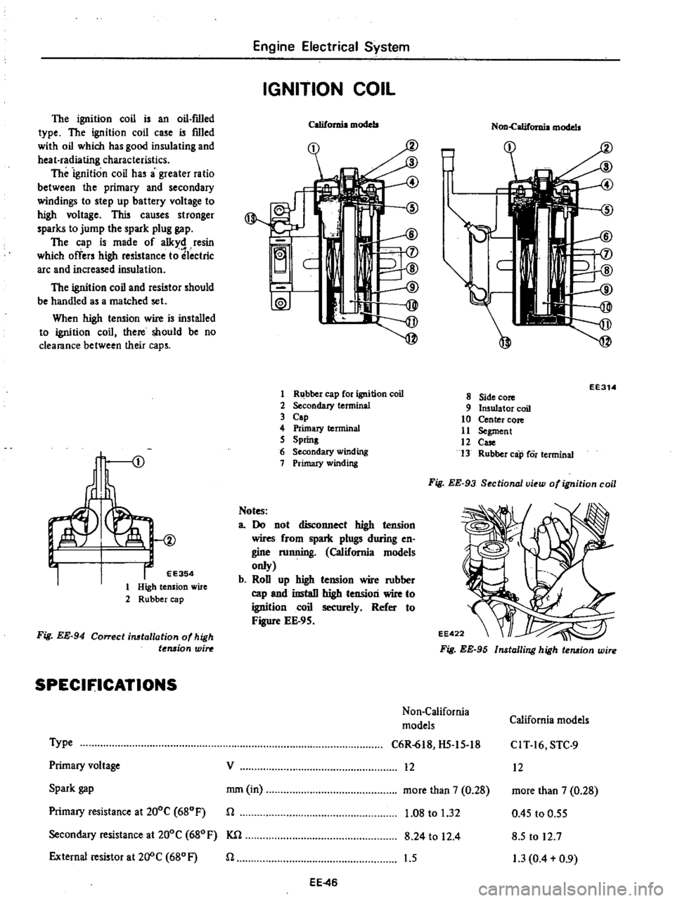
The
ignition
coil
is
an
oil
f1l1ed
type
The
ignition
coil
case
is
filled
with
oil
which
has
good
insulating
and
heat
radiating
characteristics
The
ignition
coil
has
a
greater
ratio
between
the
primary
and
secondary
windings
to
step
up
battery
voltage
t
high
voltage
This
causes
stronger
sparks
to
jump
the
spark
plug
gap
The
cap
is
made
of
alkyd
resin
which
offers
high
resistance
to
lectric
arc
and
increased
insulation
The
ignition
coil
and
resistor
should
be
handled
as
a
matched
set
When
high
tension
wire
is
installed
to
ignition
coil
there
should
be
no
clearance
between
their
caps
I
EE354
1
High
tension
wire
2
Rubber
cap
Fig
EE
94
Correcl
installation
of
high
t
Mjon
win
SPECIFICATIONS
Type
Primary
voltage
Spark
gap
Primary
resistance
at
200C
680F
Secondary
resistance
at
200C
680
F
KSl
External
resistor
at20
C
680F
n
Engine
Electrical
System
IGNITION
COIL
California
models
f
ID
@
J
C
ID
I
1W
1
R
bber
cap
for
ignition
coil
2
Secondary
terminal
3
Cap
4
Primary
terminal
5
Spring
6
Secondary
winding
7
Primary
winding
Notes
a
Do
not
disconnect
high
tension
wires
from
spark
plugs
during
en
gine
mnning
California
models
only
b
RoD
up
high
tension
wire
mbber
cap
and
instaD
high
tension
wire
to
ignition
coil
securely
Refer
to
Figure
EE
9S
Non
califomia
models
EE314
8
Side
core
9
Insulator
coil
10
Center
core
11
Segment
12
Case
13
Rubber
cap
Cor
terminal
Fig
EE
93
Sectional
view
of
ignition
coil
Fig
EE
95
Installing
high
tension
wire
Non
California
California
models
models
C6R
618
HS
15
18
CIT
16
STC
9
12
12
more
than
7
0
28
more
than
7
0
28
1
08
to
1
32
0
45
to
0
55
8
24
to
12
4
8
5
to
12
7
1
5
1
3
0
4
0
9
V
mm
in
n
EE
46