fuel cap DATSUN PICK-UP 1977 Owner's Manual
[x] Cancel search | Manufacturer: DATSUN, Model Year: 1977, Model line: PICK-UP, Model: DATSUN PICK-UP 1977Pages: 537, PDF Size: 35.48 MB
Page 165 of 537

sufficient
delivery
of
fuel
to
engine
or
vapor
lock
It
must
therefore
be
1
3
connectur
COCk
Air
Manometer
Emission
Control
System
repaired
or
replaced
368
mmH20
14
5
inH20
LL
IPO
liqUid
epo
o
36
r
@
Carbon
canister
EC786
Fig
EC
79
Checking
evaporative
emmion
control
syatem
CARBON
CANISTER
PURGE
CONTROL
VALVE
Check
for
fuel
vapor
leakage
in
the
distributor
vacuum
line
at
diaphragm
of
carbon
canister
purge
control
valve
To
check
for
leakage
proceed
as
follows
I
Disconnect
rubber
hose
in
the
line
between
T
connector
and
carbon
canister
at
T
connector
2
Inhale
air
into
the
opening
of
rubber
hose
running
to
vacuum
hole
in
carbon
canister
and
ensure
that
there
is
no
leak
ET349
Fig
EC
so
Checking
carbon
canuter
purge
control
valve
3
If
there
is
a
leak
remove
top
cover
from
purge
control
valve
and
check
for
dislocated
or
cracked
dia
phragm
If
necessary
replace
dia
phragm
kit
which
is
made
up
of
a
retainer
a
diaphragm
and
a
spring
@
@
1
Cover
2
Diaphragm
3
Retainer
4
Spring
ET350
Fig
EC
81
Carbon
catU
ter
purge
control
valve
CARBON
CANISTER
FILTER
Check
for
a
contaminated
element
Element
can
be
removed
at
the
bottom
of
canister
installed
on
vehicle
body
EC
32
ET37Q
Fig
EC
s2
Replacing
carbon
canuter
filter
FUEL
TANK
VACUUM
RELIEF
VALVE
Remove
fuel
filler
cap
and
see
it
functions
properly
I
Wipe
clean
valve
housing
and
have
it
in
your
mouth
2
Inhale
air
A
slight
resistance
ac
companied
by
valve
indicates
that
valve
is
in
good
mechanical
condition
Note
also
that
by
further
inhaling
air
the
resistance
should
be
disappeared
with
valve
clicks
3
If
valve
is
clogged
or
if
no
resist
ance
is
felt
replace
cap
as
an
assem
bled
uni
t
l
u
ET369
Fig
EC
83
Fuel
filler
cap
Page 215 of 537

Engine
Electrical
System
SERVICE
DATA
AND
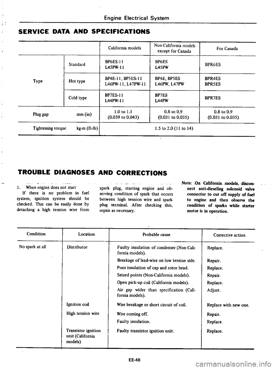
SPECIFICATIONS
California
models
Non
California
models
For
Canada
except
for
Canada
BP6ES
ll
BP6ES
BPR6ES
Standard
L45PW
ll
L45PW
BP4E
ll
BP5ES
ll
BP4E
BP5ES
BPR4ES
Type
Hot
type
L46PW
ll
L47PW
ll
L46PW
L47PW
BPR5ES
Cold
type
BP7ES
ll
BP7ES
BPR7ES
LMPW
ll
LMPW
1
0
to
l
l
0
8
to
0
9
0
8
to
0
9
Plug
gap
mm
in
0
039
to
0
043
0
031
to
0
D35
0
031
to
0
035
Tightening
torque
kg
m
ft
Ib
I
1
5
to
2
0
11
to
14
TROUBLE
DIAGNOSES
AND
CORRECTIONS
When
engine
does
not
start
If
there
is
no
problem
in
fuel
system
ignition
system
should
be
checked
This
can
be
easily
done
by
detaching
a
high
tension
wire
from
spark
plug
starting
engine
and
ob
serving
condition
of
spark
that
occurs
between
high
tension
wire
and
spark
plug
terminal
After
checking
this
repair
as
necessary
Note
On
California
models
disc
on
nect
anti
dieseling
solenoid
valve
connector
to
cut
off
supply
of
fuel
to
engine
and
then
observe
the
condition
of
spaIks
while
starter
motor
is
in
operation
Condition
Location
Probable
cause
Corrective
action
No
spark
at
all
Distributor
Faulty
insulation
of
condenser
Non
Cali
Replace
fomia
models
Breakage
of
lead
wire
on
low
tension
side
Repair
Poor
insulation
of
cap
and
rotor
head
Replace
Seized
points
Non
California
models
Repair
Open
pick
up
coil
California
models
Replace
Air
gap
wider
than
specification
Cali
Adjust
fornia
models
Ignition
coil
Wire
breakage
or
short
circuit
of
coil
Replace
with
new
one
High
tension
wire
Wire
coming
off
Repair
Faulty
insulation
Replace
Transistor
ignition
Faulty
transistor
ignition
unit
Replace
unit
California
models
EE
4B
Page 419 of 537

DESCRIPTION
REMOVAL
DESCRIPTION
The
fuel
tank
is4Sliters
II
Ji
U
s
gal
9
Ji
Imper
gal
in
capacity
The
tank
unit
is
mounted
to
the
right
side
of
the
rear
floor
1
Fuel
tank
2
Drain
plug
3
Filler
tube
4
RescfYOir
tank
5
Filler
hose
6
Breather
hose
7
Ventilation
hose
8
Evaporation
hose
9
Fuel
outlet
hose
and
tube
10
Fuel
tank
gauge
unit
11
Protector
12
Bracket
13
Retainer
14
Return
tube
Engine
Control
Fuel
Exhaust
Systems
FUEL
SYSTEM
CONTENTS
FE
4
FE
5
INSPECTION
INSTALLATION
FE
6
FE
6
The
filler
shutter
is
installed
to
the
filler
tube
on
California
models
The
electric
fuel
pump
is
adopted
on
air
conditioner
equipped
models
For
the
electric
fuel
pump
refer
to
Section
EF
FE194
Fig
FE
3
Fuel
tank
FE
4
Page 424 of 537

Engine
Control
Fuel
Exhaust
Systems
I
Wipe
clean
all
the
contact
por
tions
of
tube
joints
allow
them
to
dry
thoroughly
2
Temporarily
mount
in
place
muffler
assembly
as
an
assembled
unit
on
the
vehicle
3
Insert
front
tube
until
it
touches
emboss
m
b
nlfrnnjj
mm
lJ
Ij
@L
J
FE263
Fig
FE
ll
Exhawt
tube
connection
4
Torque
nut
securing
the
male
and
female
tubes
at
the
connection
Tightening
torque
is
1
6
to
2
0
kg
m
12
to
14
ft
lb
5
Squeeze
approximately
5
CC
0
31
cu
in
of
sealant
into
injection
from
sealant
tube
See
Figure
FE
12
Sealant
tube
polyethylene
Injector
Fig
FE
IO
Exhaust
sealant
kit
Be
sure
to
place
cap
back
to
sealant
tube
since
sealant
will
dry
Approximately
5
cc
0
31
Cll
in
FE1l1
Fig
FE
12
Squeezing
sealant
to
injec
tor
6
Position
nozzle
of
injector
to
the
guide
and
press
it
there
firmly
Inject
sealant
slowly
until
sealant
begins
to
flow
out
of
the
slit
of
tube
This
indicates
that
the
bead
requires
no
further
sealant
Excessive
sealant
can
cause
a
clogged
tube
See
Figure
FE
13
After
injecting
wash
injector
thoroughly
in
clean
water
to
remove
all
traces
of
sealant
FE191
Fig
FE
13
Injecting
sealant
FE
9
7
Start
engine
and
let
it
idle
slowly
for
ten
minutes
minimum
to
hilfden
sealant
with
the
heat
of
exhaust
gas
8
Check
the
condition
of
sealant
before
driving
the
vehicle
It
is
also
essential
that
the
vehicle
should
not
be
accelerated
sharply
for
20
to
30
minutes
subsequent
to
this
operation
Noles
a
The
sealant
should
be
used
within
guaranty
term
indicated
on
the
kit
case
b
Exposure
of
sealant
to
the
skin
may
cause
a
rash
Wash
sealant
off
the
skin
with
water
c
Do
not
keep
the
sealant
tube
in
a
place
where
the
ambient
tempera
ture
is
above
400C
I040F
A
sealant
hardened
above
4QoC
I040F
cannot
be
used
The
most
suitable
storage
temperature
is
from
15
to
350C
59
to
950F
If
sealant
becomes
hardened
because
of
low
temperatures
wann
the
sealant
tube
with
lukewarm
water
until
the
sealant
is
softened
Do
not
warm
tube
at
a
temperature
over
400C
1040F
for
a
long
time
d
Thoroughly
read
the
instruction
sheet
furnished
with
the
kit
before
using
the
sealant
i
Page 480 of 537

Body
Electrical
System
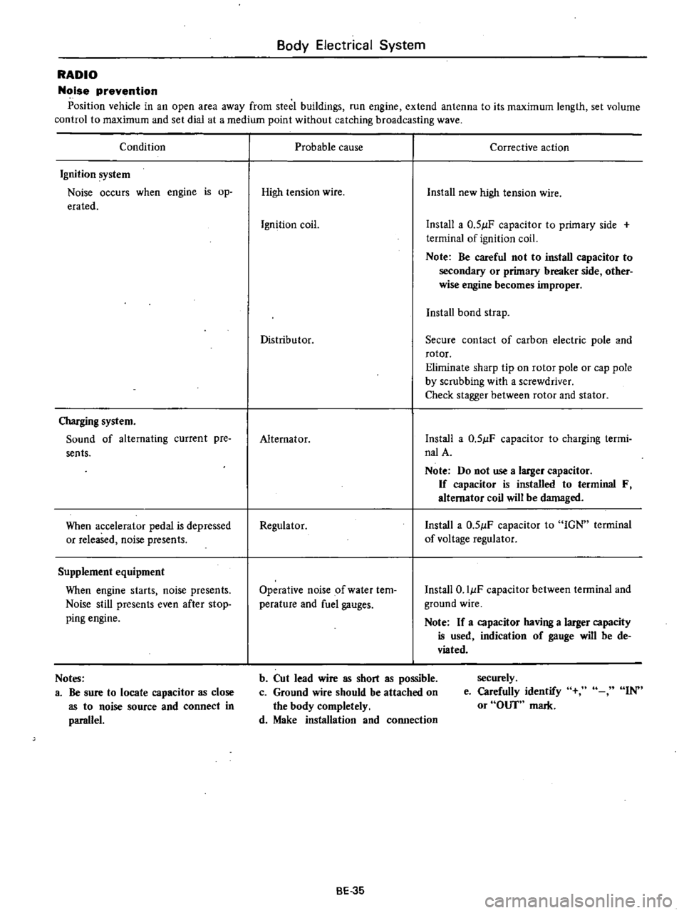
RADIO
Noise
prevention
Position
vehicle
in
an
open
area
away
from
steel
buildings
run
engine
extend
antenna
to
its
maximum
length
set
volume
control
to
maximum
and
set
dial
at
a
medium
point
without
catching
broadcasting
wave
Condition
Ignition
system
Noise
occurs
when
engine
is
op
erated
Charging
system
Sound
of
alternating
current
pre
sents
When
accelerator
pedal
is
depressed
or
released
noise
presents
Supplement
equipment
When
engine
starts
noise
presents
Noise
still
presents
even
after
stop
ping
engine
Notes
a
Be
sure
to
locate
capacitor
as
close
as
to
noise
source
and
connect
in
parallel
Probable
cause
Corrective
action
High
tension
wire
Install
new
high
tension
wire
Ignition
coil
Install
a
0
51lF
capacitor
to
primary
side
terminal
of
ignition
coil
Note
Be
careful
not
to
install
capacitor
to
secondary
or
primary
breaker
side
other
wise
engine
becomes
improper
Install
bond
strap
Distributor
Secure
contact
of
carbon
electric
pole
and
rotor
Eliminate
sharp
tip
on
rotor
pole
or
cap
pole
by
scrubbing
with
a
screwdriver
Check
stagger
between
rotor
and
stator
Alternator
Install
a
0
51lF
capacitor
to
charging
termi
nalA
Note
Do
not
use
a
larger
capacitor
If
capacitor
is
installed
to
terminal
F
alternator
coil
will
be
damaged
Regulator
Install
a
0
51lF
capacitor
to
IGN
terminal
of
voltage
regulator
Operative
noise
of
water
tem
perature
and
fuel
gauges
Install
O
IIlF
capacitor
between
terminal
and
ground
wire
Note
If
a
capacitor
having
a
larger
capacity
is
used
indication
of
gauge
will
be
de
viated
b
Cut
lead
wire
as
short
as
possible
c
Ground
wire
should
be
attached
on
the
body
completely
d
Make
installation
and
connection
securely
e
Carefully
identify
or
OUT
mark
IN
BE
35