air condition DATSUN PICK-UP 1977 Owner's Guide
[x] Cancel search | Manufacturer: DATSUN, Model Year: 1977, Model line: PICK-UP, Model: DATSUN PICK-UP 1977Pages: 537, PDF Size: 35.48 MB
Page 109 of 537
Engine
Fuel
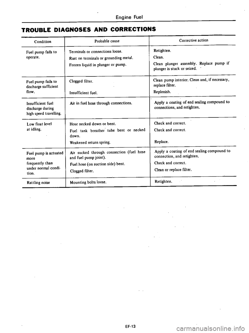
TROUBLE
DIAGNOSES
AND
CORRECTIONS
Condition
Fuel
pump
fails
to
operate
Fuel
pump
fails
to
discharge
sufficient
flow
Insufficient
fuel
discharge
during
high
speed
travelling
Low
float
level
at
idling
Fuel
pump
is
actuated
more
frequently
than
under
normal
condi
tion
Rattling
noise
Probable
cause
Terminals
or
connections
loose
Rust
on
terminals
or
grounding
metal
Frozen
liquid
in
plunger
or
pump
Clogged
filter
Insufficient
fuel
Air
in
fuel
hose
through
connections
Hose
necked
down
or
bent
Fuel
tank
breather
tube
bent
or
necked
down
Weakened
return
spring
Air
sucked
through
connection
fuel
hose
and
fuel
pump
joint
Fuel
hose
on
suction
side
bent
Clogged
fIlter
Mounting
bolts
loose
EF
13
Corrective
action
Retighten
Clean
Clean
plunger
assembly
Replace
pump
if
plunger
is
stuck
or
seized
Clean
pump
interior
Clean
and
if
necessary
replace
fIlter
Replenish
Apply
a
coating
of
end
sealing
compound
to
connections
and
retighten
Check
and
correct
Check
and
correct
Replace
Apply
a
coating
of
end
sealing
compound
to
connection
and
retighten
Check
and
correct
Clean
or
replace
fIlter
Retighten
Page 110 of 537
Engine
Fuel
CARBURETOR
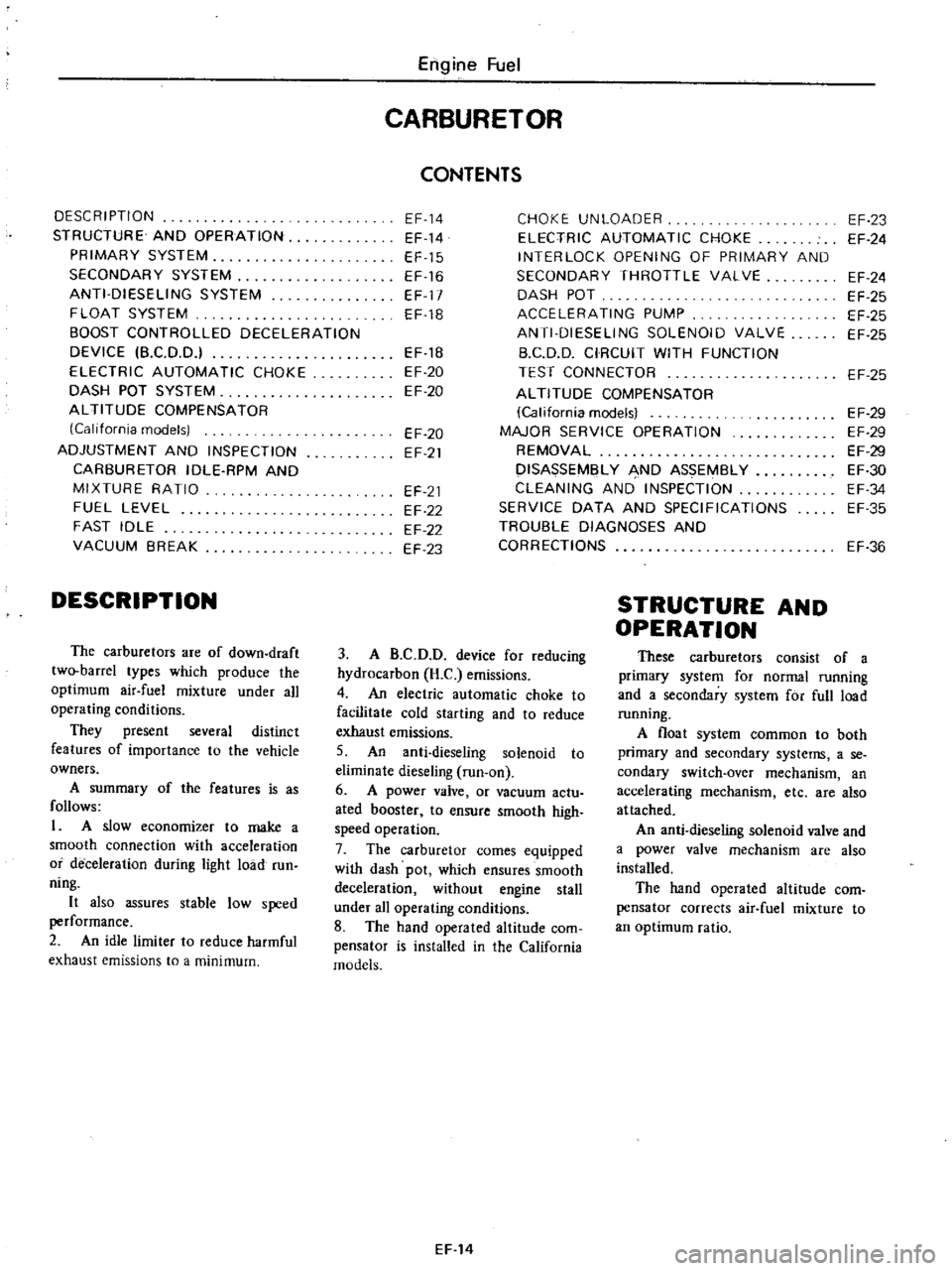
CONTENTS
DESCRIPTION
EF
14
CHOKE
UNLOADER
EF
23
STRUCTURE
AND
OPERATION
EF
14
ELECTRIC
AUTOMATIC
CHOKE
EF
24
PRIMARY
SYSTEM
EF
15
INTERLOCK
OPENING
OF
PRIMARY
AND
SECONDARY
SYSTEM
EF
16
SECONDARY
THROTTLE
VALVE
EF
24
ANTI
DIESELING
SYSTEM
EF
17
DASH
POT
EF
25
FLOAT
SYSTEM
EF
18
ACCELERATING
PUMP
EF
25
BOOST
CONTROLLED
DECELERATION
ANTI
DIESELING
SOLENOID
VALVE
EF
25
DEVICE
B
C
D
D
EF
1B
B
C
D
D
CIRCUIT
WITH
FUNCTION
ELECTRIC
AUTOMATIC
CHOKE
EF
20
TEST
CONNECTOR
EF
25
DASH
POT
SYSTEM
EF
20
ALTITUDE
COMPENSATOR
ALTITUDE
COMPENSATOR
California
modelsl
EF
29
California
models
EF
20
MAJOR
SERVICE
OPERATION
EF
29
ADJUSTMENT
AND
INSPECTION
EF
21
REMOVAL
EF
29
CARBURETOR
IDLE
RPM
AND
DISASSEMBLY
AND
ASSEMBLY
EF
30
MIXTURE
RATIO
EF
21
CLEANING
AND
INSPECTION
EF
34
FUEL
LEVEL
EF
22
SERVICE
DATA
AND
SPECIFICATIONS
EF
35
FAST
IDLE
EF
22
TROU8LE
DIAGNOSES
AND
VACUUM
BREAK
EF
23
CORRECTIONS
EF
36
DESCRIPTION
The
carburetors
are
of
down
draft
two
barrel
types
which
produce
the
optimum
air
fuel
mixture
under
all
operating
conditions
They
present
several
distinct
features
of
importance
to
the
vehicle
owners
A
summary
of
the
features
is
as
follows
1
A
slow
economizer
to
make
a
smooth
connection
with
acceleration
or
deceleration
during
light
load
run
ning
It
also
assures
stable
low
speed
performance
2
An
idle
limiter
to
reduce
harmful
exhaust
emissions
to
a
minimum
3
A
B
C
D
D
device
for
reducing
hydrocarbon
H
C
emissions
4
An
electric
automatic
choke
to
facilitate
cold
starting
and
to
reduce
exhaust
emissions
5
An
anti
dieseling
solenoid
to
eliminate
dieseling
run
on
6
A
power
valve
or
vacuum
actu
ated
booster
to
ensure
smooth
high
speed
operation
7
The
carburetor
comes
equipped
with
dash
pot
which
ensures
smooth
deceleration
without
engine
stall
under
all
operating
conditions
8
The
hand
operated
altitude
com
pensator
is
installed
in
the
California
models
EF
14
STRUCTURE
AND
OPERATION
These
carburetors
consist
of
a
primary
system
for
normal
running
and
a
secondary
system
for
full
load
running
A
float
system
common
to
both
primary
and
secondary
systems
a
se
condary
switch
over
mechanism
an
accelerating
mechanism
etc
are
also
attached
An
anti
dieseling
solenoid
valve
and
a
power
valve
mechanism
are
also
installed
The
hand
operated
altitude
com
pensator
corrects
air
fuel
mixture
to
an
optimum
ratio
Page 116 of 537
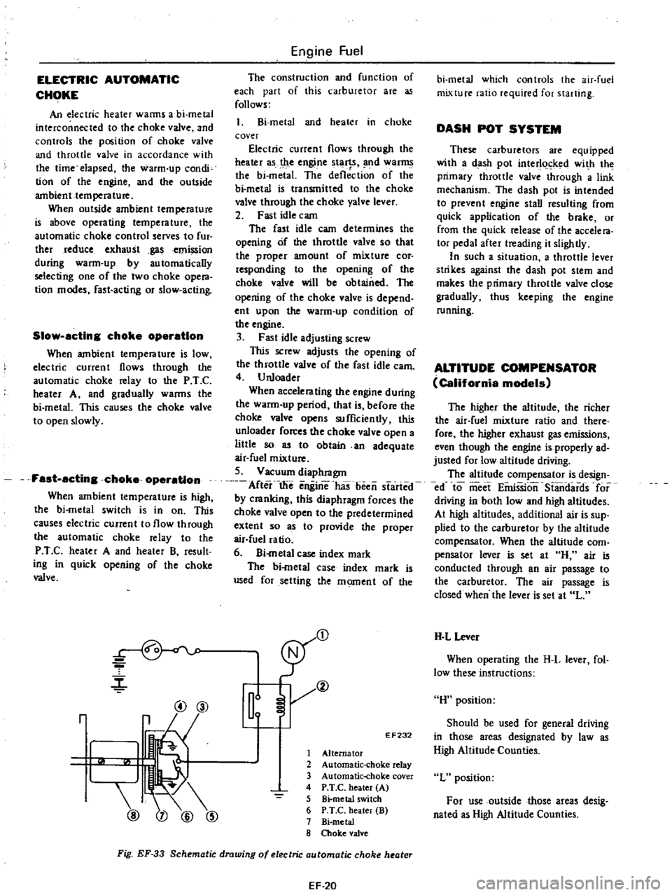
ELECTRIC
AUTOMATIC
CHOKE
An
electric
heater
wanns
a
bi
metal
interconnected
to
the
choke
valve
and
controls
the
position
of
choke
valve
and
throttle
valve
in
accordance
with
the
time
elapsed
the
warm
up
condi
tion
of
the
engine
and
the
outside
ambient
temperature
When
outside
ambient
temperature
is
above
operating
temperature
the
automatic
choke
control
serves
to
fur
ther
reduce
exhaust
gasemission
during
warm
up
by
automatically
selecting
one
of
the
two
choke
opera
tion
modes
fast
acting
or
slow
acting
Slow
acting
choke
operation
When
ambient
temperature
is
low
electric
current
flows
through
the
automatic
choke
relay
to
the
P
T
C
heater
A
and
gradually
warms
the
bi
metal
This
causes
the
choke
valve
to
open
slowly
Fast
acting
choke
operation
When
ambient
temperature
is
high
the
bi
metal
switch
is
in
on
This
causes
electric
current
to
flow
through
the
automatic
choke
relay
to
the
P
T
C
heater
A
and
heater
B
result
ing
in
quick
opening
of
the
choke
valve
r
@@
r
@
Engine
Fuel
The
construction
and
function
of
each
part
of
this
carburetor
are
as
follows
l
Bi
metal
and
heater
in
choke
cover
Electric
current
flows
through
the
ttea
r
as
t
le
engine
tl
1
SI
nd
war
the
bi
metal
The
deflection
of
the
bi
metal
is
transmitted
to
the
choke
valve
through
the
choke
yalve
lever
2
Fast
idle
cam
The
fast
idle
cam
determines
the
opening
of
the
throttle
valve
so
that
the
proper
amount
of
mixture
cor
responding
to
the
opening
of
the
choke
valve
will
be
obtained
The
opening
of
the
choke
valve
is
depend
ent
upon
the
warm
up
condition
of
the
engine
3
Fast
idle
adjusting
screw
This
screw
adjusts
the
opening
of
the
throttle
valve
of
the
fast
idle
earn
4
U
nloader
When
accelerating
the
engine
during
the
warm
up
period
that
is
before
the
choke
valve
opens
sufficiently
this
unloader
forces
the
choke
valve
open
a
liUle
so
as
to
obtain
an
adequate
air
fuel
mixture
5
Vacuum
diaphragm
After
the
enginThas
been
started
by
cranking
this
diaphragm
forces
the
choke
valve
open
to
the
predetermined
extent
so
as
to
provide
the
proper
air
fuel
ratio
6
Bi
metal
case
index
mark
The
bi
metal
case
index
mark
is
used
for
setting
the
moment
of
the
D
Il
EF232
1
Alternator
2
Automatic
choke
relay
3
Automatic
choke
cover
4
P
T
C
heater
A
5
Bi
metal
switch
6
P
T
C
heater
B
7
Bi
metal
8
Choke
valve
Fig
EF
33
Schematic
drawing
of
electric
automatic
choke
heater
EF
20
bi
metal
which
controls
the
air
fuel
mixture
ratio
required
for
starting
DASH
POT
SYSTEM
These
carburetors
are
equipped
with
a
dash
pot
interl
ked
wi
h
the
primary
throttle
valve
through
a
link
mechanism
The
dash
pot
is
intended
to
prevent
engine
stall
resulting
from
quick
application
of
the
brake
or
from
the
quick
release
of
the
accele
ra
tor
pedal
after
treading
it
slightly
In
such
a
situation
a
throttle
lever
strikes
against
the
dash
pot
stem
and
makes
the
primary
throttle
valve
close
gradually
thus
keeping
the
engine
running
ALTITUDE
COMPENSATOR
California
models
The
higher
the
altitude
the
richer
the
air
fuel
mixture
ratio
and
there
fore
the
higher
exhaust
gas
emissions
even
though
the
engine
is
properly
ad
justed
for
low
altitude
driving
The
altitude
compensator
is
design
ed
to
meet
EiiriSSion
S13ndards
for
driving
in
both
low
and
high
altitudes
At
high
altitudes
additional
air
is
sup
plied
to
the
carburetor
by
the
altitude
compensator
When
the
altitude
com
pensator
lever
is
set
at
H
air
is
conducted
through
an
air
passage
to
the
carburetor
The
air
passage
is
closed
when
the
lever
is
set
at
L
H
L
Lever
When
operating
the
H
L
lever
fol
low
these
instructions
H
position
Should
be
used
for
general
driving
in
those
areas
designated
by
law
as
High
Altitude
Counties
L
position
For
use
outside
those
areas
desig
nated
as
High
Altitude
Counties
Page 117 of 537
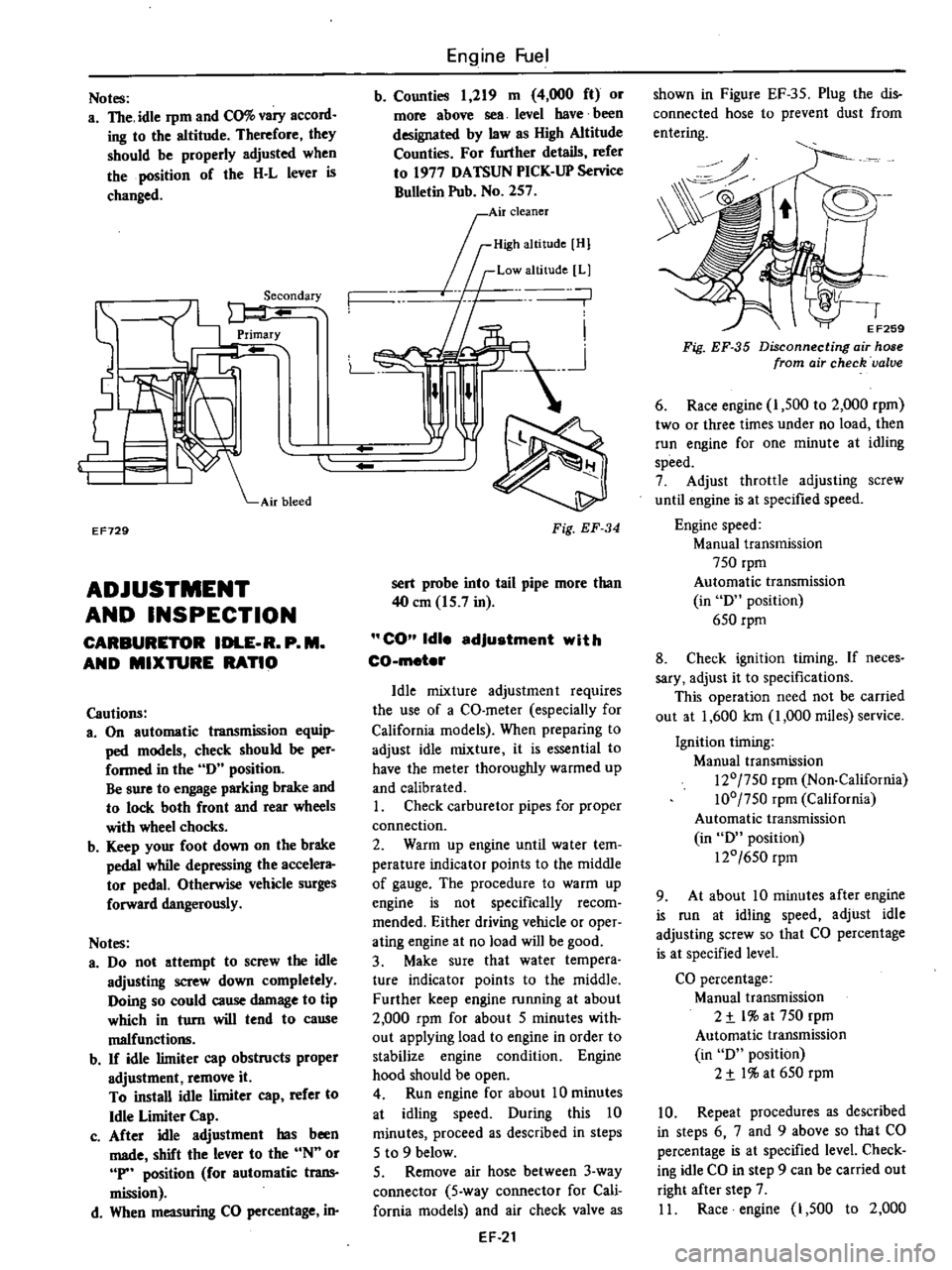
Notes
a
The
idle
rpm
and
CO
vary
accord
ing
to
the
altitude
Therefore
they
should
be
properly
adjusted
when
the
position
of
the
H
L
lever
is
changed
EF729
ADJUSTMENT
AND
INSPECTION
CARBURETOR
IDLE
R
P
M
AND
MIXTURE
RATIO
Cautions
3
On
automatic
transmission
equi
ped
models
check
should
be
per
formed
in
the
0
position
Be
sure
to
engage
parking
brake
and
to
lock
both
front
and
rear
wheels
with
wheel
chocks
b
Keep
your
foot
down
on
the
brake
pedal
while
depressing
the
accelera
tor
pedal
Otherwise
vehicle
surges
forward
dangerously
Notes
a
00
not
attempt
to
screw
the
idle
adjusting
screw
down
completely
Ooing
so
could
cause
damage
to
tip
which
in
turn
will
tend
to
cause
malfunctio11ll
b
If
idle
limiter
cap
obstructs
proper
adjustment
remove
it
To
install
idle
limiter
cap
refer
to
Idle
Limiter
Cap
c
After
idle
adjustment
has
been
made
shift
the
lever
to
the
N
or
P
position
for
automatic
trans
mission
d
When
measuring
CO
percentage
in
Engine
Fuel
b
Counties
1
219
m
4
000
ft
or
more
above
sea
level
have
been
designated
by
law
as
High
Altitude
Counties
For
further
details
refer
to
1977
OATSUN
PICK
UP
Service
Bulletin
Pub
No
257
0
I
Air
cleaner
rID
mOl
If
Low
altitude
Ll
n
n
L
n
Fig
EF
34
sert
probe
into
tail
pipe
more
than
40
em
15
7
in
CO
Idle
adjustment
with
CO
meter
Idle
mixture
adjustment
requires
the
use
of
a
CO
meter
especially
for
California
models
When
preparing
to
adjust
idle
mixture
it
is
essential
to
have
the
meter
thoroughly
warmed
up
and
calibrated
I
Check
carburetor
pipes
for
proper
connection
2
Warm
up
engine
until
water
tem
perature
indicator
points
to
the
middle
of
gauge
The
procedure
to
warm
up
engine
is
not
specifically
recom
mended
Either
driving
vehicle
or
oper
ating
engine
at
no
load
will
be
good
3
Make
sure
that
water
tempera
ture
indicator
points
to
the
middle
Further
keep
engine
running
at
about
2
000
rpm
for
about
5
minutes
with
out
applying
load
to
engine
in
order
to
stabilize
engine
condition
Engine
hood
should
be
open
4
Run
engine
for
about
10
minutes
at
idling
speed
Ouring
this
10
minutes
proceed
as
described
in
steps
5
to
9
below
5
Remove
air
hose
between
3
way
connector
5
way
connector
for
Cali
fornia
models
and
air
check
valve
as
EF
21
shown
in
Figure
EF
35
Plug
the
dis
connected
hose
to
prevent
dust
from
entering
0
o
EF259
Fig
EF
35
Disconnecting
air
hose
from
air
check
valve
6
Race
engine
I
500
to
2
000
rpm
two
or
three
times
under
no
load
then
run
engine
for
one
minute
at
idling
speed
7
Adjust
throttle
adjusting
screw
until
engine
is
at
specified
speed
Engine
speed
Manual
transmission
750
rpm
Automatic
transmission
in
0
position
650
rpm
8
Check
ignition
timing
If
neces
sary
adjust
it
to
specifications
This
operation
need
not
be
carried
out
at
1
600
Ian
1
000
miles
service
Ignition
timing
Manual
transmission
120
750
rpm
Non
California
100
750
rpm
California
Automatic
transmission
in
0
position
120
650
rpm
9
At
about
10
minutes
after
engine
is
run
at
idling
speed
adjust
idle
adjusting
screw
so
that
CO
percentage
is
at
specified
level
CO
percentage
Manual
transmission
2
t
l
at
750
rpm
Automatic
transmission
in
0
position
2
t
I
at
650
rpm
10
Repeat
procedures
as
described
in
steps
6
7
and
9
above
so
that
CO
percentage
is
at
specified
level
Check
ing
idle
CO
in
step
9
can
be
carried
out
right
after
step
7
II
Race
engine
1
500
to
2
000
Page 118 of 537
rpm
two
or
three
iimes
under
no
load
and
make
sure
that
specified
CO
per
centage
is
obtained
12
Connect
air
hose
to
air
check
valve
If
engine
speed
increases
readjust
it
to
the
specified
speed
with
throttle
adjustingsqew
CO
idle
edJustment
without
CO
meter
If
CO
meter
is
not
available
the
following
procedures
may
be
used
L
Check
carburetor
pipes
for
proper
connection
2
Warm
up
engine
until
water
tem
perature
indicator
points
to
the
middle
of
gauge
The
procedure
to
warm
up
engine
is
not
specifically
recom
mended
Either
driving
vehicle
or
oper
ating
engine
at
no
load
will
be
good
3
Make
sure
that
water
temperature
indicator
points
to
the
middle
Further
keep
engine
running
at
about
2
000
rpm
for
about
5
minutes
without
applying
load
to
engine
in
order
to
stabilize
engine
condition
Engine
hood
should
be
open
4
Run
engine
for
about
10
minutes
at
idling
speed
During
this
10
minutes
proceed
as
described
in
steps
5
to
9
below
5
Remove
air
hose
between
3
way
connector
5
way
connector
for
Cali
fornia
models
and
air
check
valve
shown
in
Figure
EF
35
Plug
the
dis
connected
hose
19
prevent
dust
from
entering
6
Race
engine
1
500
to
2
000
rpm
two
or
three
times
under
no
load
then
run
engine
for
one
minute
at
idling
speed
7
Adjust
throttle
adjusting
screw
so
that
engine
speeds
are
as
indicated
below
Engine
speed
Manual
transmission
815
rpm
Automatic
transmission
in
D
position
670
rpm
8
Check
ignition
timing
if
neces
sary
adjust
it
to
the
value
required
by
specifications
This
operation
need
not
be
carried
out
at
1
600
km
1
000
miles
service
9
At
about
10
minutes
after
engine
Engine
Fuel
is
run
at
idling
speed
adjust
idle
adjusting
screw
until
maximum
rpm
is
obtained
10
Repeat
procedures
as
described
in
steps
6
7
and
9
above
until
engine
speed
at
best
idle
mixture
is
815
rpm
for
manual
transmission
models
and
670
rpm
for
automatic
transmission
models
in
D
position
Adjustment
in
step
9
can
be
carried
out
right
after
step
7
11
Turn
the
idle
adjusting
screw
clockwise
until
engine
speed
drops
off
below
specified
rpm
Engine
speed
drops
off
Manual
transmission
60
to
70
rpm
Automatic
transmission
in
D
position
15
to
25
rpm
12
Connect
air
hose
to
air
check
valve
If
engine
speed
increases
readjust
it
to
the
specified
speed
with
throttle
adjusting
screw
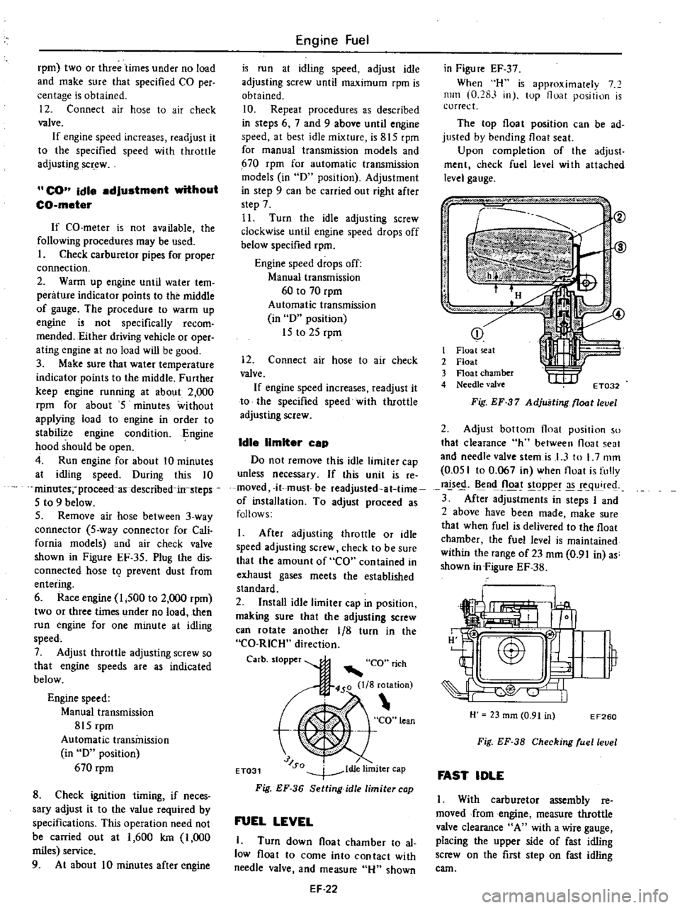
Idle
limiter
cep
Do
not
remove
this
idle
limiter
cap
unless
necessary
If
this
unit
is
re
moved
it
must
be
readjusted
at
lime
of
installation
To
adjust
proceed
as
follows
I
After
adjusting
throttle
or
idle
speed
adjusting
screw
check
to
be
sure
that
the
amount
of
CO
contained
in
exhaust
gases
meets
the
established
standard
2
Install
idle
limiter
cap
in
position
making
sure
that
the
adjusting
screw
can
rotate
another
1
8
turn
in
the
CO
RICH
direction
Carbo
to
per
CO
rich
450
lIS
rotation
t
CO
lean
J
SQ
dl
lim
ET031
1
e
Iter
cap
Fig
EF
36
Setting
idle
limiter
cap
FUEL
LEVEL
1
Turn
down
float
chamber
to
al
low
float
to
come
into
contact
with
needle
valve
and
measure
Hu
shown
EF
22
in
Figu
re
EF
37
When
H
is
approximalely
7
mill
0
283
in
lOp
float
position
is
correct
The
top
float
position
can
be
ad
justed
by
bending
float
seat
Upon
completion
of
the
adjust
ment
check
fuel
level
wi
th
attached
level
gauge
p
j
i
I
it
I
Float
seat
2
Float
3
Float
chamber
4
Needle
valve
t
I
IIf
ET032
Fig
EF
37
Adjusting
float
level
2
Adjust
bottom
float
position
so
that
clearance
h
between
float
seat
and
needle
valve
stemis
I
3
to
L
7
mm
0
051
to
0
067
in
when
Iloat
is
fully
rals
n
Jloa
t
goppe
q
re
3
After
adjustments
in
steps
I
and
2
above
have
been
made
make
sure
that
when
fuel
is
delivered
to
the
float
chamber
the
fuel
level
is
maintained
within
the
range
of23
mm
0
91
in
as
shown
in
FigureEF
38
H
23
mm
0
91
in
EF260
Fig
EF
38
Checking
ruellevel
FAST
IDLE
I
With
carburetor
assembly
reo
moved
from
engine
measure
throttle
valve
clearance
A
with
a
wire
gauge
placing
the
upper
side
of
fast
idling
screw
on
the
first
step
on
fast
idling
cam
Page 125 of 537
I
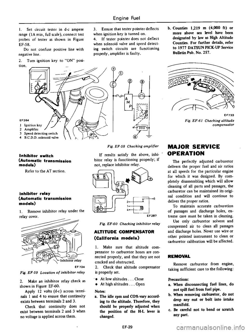
Set
circuit
tester
in
d
c
ampere
range
IA
min
fuU
scale
connect
test
probes
of
tester
as
shown
in
Figure
EF
58
Do
not
confuse
positive
line
with
negative
line
2
Turn
ignition
key
to
ON
posi
tion
I
t
EF264
1
Ignition
key
2
Amplifier
3
Speed
detecting
switch
4
B
C
D
D
solenoid
valve
Inhibitor
switch
Automatic
transmission
models
Refer
to
the
AT
section
Inhibitor
relay
Automatic
transmission
models
Inhibitor
relay
EF724
Fig
EF
59
Location
of
inhibitor
relay
2
Make
an
inhibitor
relay
check
as
shown
in
Figure
EF
60
Apply
12
volts
d
c
across
termi
nals
1
and
4
to
ensure
that
continuity
exists
between
terminals
2
and
3
Check
that
continuity
does
not
exist
between
terminals
2
and
3
when
no
voltage
is
applied
across
them
Engine
Fuel
3
Ensure
that
tester
pointer
deflects
when
ignition
key
is
turned
on
4
If
tester
pointer
does
not
deflect
when
solenoid
valve
and
speed
detect
ing
switch
circuits
are
functioning
properly
amplifier
is
faulty
Fig
EF
58
Checking
amplifier
If
results
satisfy
the
above
inhi
bitor
relay
is
functioning
properly
if
not
replace
inhibitor
relay
it
@
j
l
j
4
L
I
44
11
oJ
EF287
Fig
EF
60
Checking
inhibitor
relay
ALTITUDE
COMPENSATOR
California
models
Make
sure
that
altitude
com
pensator
to
carburetor
hoses
are
con
nected
properly
and
that
they
are
not
cracked
and
obstructed
2
Check
that
altitude
compensator
is
properly
set
At
low
altitudes
At
high
altitudes
Notes
a
The
idle
Pm
and
CO
vary
accord
ing
to
the
altitude
Therefore
they
should
be
properly
adjusted
when
the
position
of
the
H
L
lever
is
changed
Close
Open
EF
29
b
Counties
1
219
m
4
000
ft
or
more
above
sea
level
have
been
designated
by
law
as
High
Altitude
Counties
For
further
details
refer
to
1977
DATSUN
PICK
UP
Service
BuUetin
Pub
No
257
Q0
1
v
EF733
Fig
EF
61
Checking
altitude
compensator
MAJOR
SERVICE
OPERATION
The
perfectly
adjusted
carburetor
delivers
the
proper
fuel
and
air
ratios
at
all
speeds
for
the
particular
engine
for
which
it
was
designed
By
com
pletely
disassembling
which
will
allow
deaning
of
all
parts
and
passages
the
carburetor
can
be
maintained
its
origi
nal
condition
and
will
continue
to
deliver
the
proper
ratios
To
maintain
accurate
carburetion
of
passages
and
discharge
holes
ex
treme
care
must
be
taken
in
cleaning
Use
only
carburetor
solvent
and
compressed
air
to
clean
all
passages
and
discharge
holes
Never
use
wire
or
other
pointed
instrument
to
clean
or
carburetor
calibration
will
be
affected
REMOVAL
Remove
carburetor
from
engine
taking
sufficient
care
to
the
following
Precautions
a
When
disconnecting
fuel
lines
do
not
spill
fuel
from
fuel
pipe
b
When
removing
carburetor
do
not
drop
any
nut
or
bolt
into
intake
manifold
c
Be
careful
not
to
bend
or
scratch
any
part
Page 130 of 537
CLEANING
AND
INSPECTION
Dirt
gum
wuler
or
l
arbon
con
taminatiun
in
or
on
exterior
moving
parts
of
a
arburctor
arc
often
respon
sihk
for
unsatisfactory
performance
For
this
reason
efficient
carbutetioll
dcpends
upon
careful
cleaning
and
inspection
while
servicing
I
Blow
all
passages
and
castings
with
compressed
air
and
blow
off
all
parts
until
dry
Note
Do
not
pass
drills
or
wires
through
calibrated
jet
or
passaaa
as
this
may
enlarge
orirlce
and
seriously
affect
carburetor
calibrs
lion
2
Check
all
parts
for
wear
If
wear
is
noted
damaged
parts
must
be
re
placed
Note
especially
the
following
Engine
Fuel
I
Check
float
needle
and
seat
for
wear
If
wear
is
noted
assembly
must
be
replaced
2
Check
throule
and
choke
shaft
bores
in
throtlle
chamber
and
choice
chamber
for
wear
or
out
of
roundness
3
Inspect
idle
adjusting
needle
for
burrs
or
ridges
Such
a
condition
re
quires
replacemen
1
3
Inspect
gaskets
0
see
if
they
appear
hard
or
briUle
or
if
edges
are
torn
or
distorted
If
any
such
condi
tion
i
noted
they
must
be
replaced
4
Check
filter
screen
for
dirt
or
lint
Clean
and
if
screen
is
distorted
or
remain
plugged
replace
5
Check
linkage
for
operating
condition
6
Inspect
operation
of
accelerating
pump
Pour
f
el
into
jloat
chamber
and
make
throtlle
lever
operate
Check
condition
of
fuel
injection
from
the
EF
34
accelerating
nowe
7
Push
connecting
rod
of
dia
phragm
chamber
and
block
passage
of
vacuum
with
finger
When
connecting
rod
becomes
free
check
for
leakage
of
air
or
damage
to
diaphragm
Jets
Carburetor
performance
depends
on
jet
and
air
bleed
That
is
why
these
components
must
be
fabricated
with
utmost
care
To
clean
them
use
cleaning
solvent
and
blow
air
on
them
Larger
inner
numbers
tamped
on
the
jet
indicate
larger
diameters
Ac
cordingly
main
and
slow
jets
with
lalger
nUmbers
provide
richer
mixture
the
smaller
the
numbers
the
leaner
the
mixture
Conversely
the
main
and
slow
air
bleeds
through
which
air
to
passes
through
make
the
fueLleaner
if
they
bear
larger
numbers
the
smaller
the
numbers
the
richer
the
fuel
Page 132 of 537
Engine
Fuel
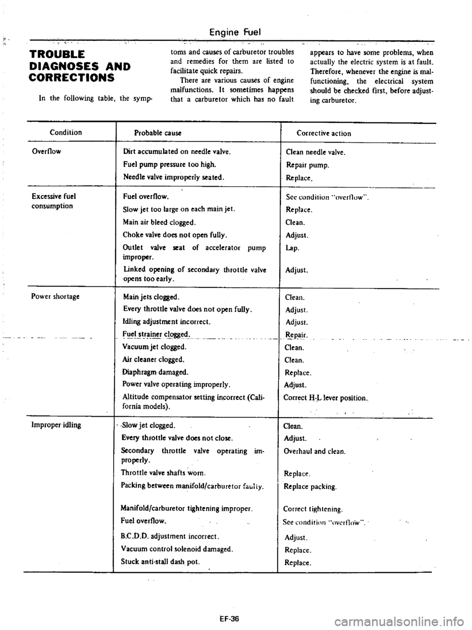
toms
and
causes
of
carburetor
troubles
and
remedies
for
them
are
listed
to
facilitate
quick
repairs
There
are
various
causes
of
engine
malfunctions
It
sometimes
happens
that
a
carburetor
which
has
no
fault
TROUBLE
DIAGNOSES
AND
CORRECTIONS
In
the
following
table
the
syml
Condition
Probable
cause
Overflow
Dirt
accumulated
on
needle
valve
Fuel
pump
pressure
too
high
Needle
valve
improperly
seated
Excessive
fuel
consumption
Fuel
overflow
Slow
jet
too
large
on
each
main
jet
Main
air
bleed
clogged
Choke
valve
does
not
open
fully
Outlet
valve
seat
of
accelerator
pump
improper
Linked
opening
of
secondary
throttle
valve
opens
too
early
Power
shortage
Main
jets
clogged
Every
throttle
valve
does
not
open
fully
Idling
adjustment
incorrect
FIICI
tr
clogged
Vacuum
jet
clogged
Air
c1eane
clogged
Diaphragm
damaged
Power
valve
operating
improperly
Altitude
compensator
setting
incorrect
Cali
fornia
models
Improper
idling
Slow
jet
clogged
Every
throttle
valve
does
not
close
Secondary
throttle
valve
operating
im
properly
Throttle
valve
shafts
worn
Packing
between
manifold
carburetor
fauJiy
Manifold
carburetor
tightening
improper
Fuel
overflow
B
C
D
D
adjustment
incorrect
Vacuum
control
solenoid
damaged
Stuck
anti
stall
dash
pot
EF
36
appears
to
have
some
problems
when
actually
the
electric
system
is
at
fault
Therefore
whenever
the
engine
is
mal
functioning
the
electrical
system
should
be
checked
rust
before
adjust
ing
carburetor
Corrective
action
Clean
needle
valve
Repair
pump
Re
place
See
condition
overflow
Replace
Clean
Adjust
Lap
Adjust
Clean
Adjust
AdjusL
pa
ir
Clean
Clean
Replace
Adjust
Correct
H
L
lever
position
Clean
Adjust
Overhaul
and
clean
Replace
Replace
packing
Correct
tightening
See
l
ondition
ov
rl1ow
Adjust
Replace
Replace
Page 135 of 537

There
are
three
types
of
control
system
These
are
J
Closed
type
CIllnkcase
emission
control
system
Emission
Control
System
of
GENERAL
DESCRIPTION
2
Exhaust
emission
control
system
3
Evaporative
ell
lhsion
control
sys
tem
Pericxiic
inspection
and
required
seCV1Clng
of
these
systems
should
be
carried
out
to
reduce
harmful
emis
sions
to
a
minimum
CRANKCASE
EMISSION
CONTROL
SYSTEM
c
01
Lkf
If
1
TIL
II
tll
1
j
GUuuu
DESCRIPTION
This
system
returns
blow
by
gas
to
both
the
intake
manifold
and
carbure
tor
air
cleaner
The
positive
crankcase
ventilation
p
C
V
valve
is
provided
to
conduct
crankcase
blow
by
gas
to
the
intake
manifold
During
partial
throttle
operation
of
the
engine
the
intake
manifold
sucks
the
blow
by
gas
through
the
P
C
V
valve
Normally
the
capacity
of
the
valve
is
sufficient
to
handle
any
blow
by
and
a
small
amount
of
ventilating
air
4
c
Fresh
air
Blow
by
gas
The
ventilating
air
is
then
drawn
from
the
dust
side
of
the
cadlUretor
air
cleaner
tluough
the
tube
con
necting
carburetor
air
cleaner
to
rock
er
cover
into
the
crankcase
Under
full
tluottle
condition
the
manifold
vacuwn
is
insufficient
to
draw
the
blow
by
flow
tluough
the
valve
and
its
flow
goes
through
the
tube
connection
in
the
reverse
diree
tion
On
vehicles
with
an
excessively
high
blow
by
some
of
the
flow
will
go
through
the
tube
connection
to
carbu
retor
air
cleaner
under
all
conditions
1
Sealtypc
oil
level
gauge
2
Bame
plate
3
Flame
arrester
4
Filler
5
P
C
Y
valve
6
Steel
net
7
Bame
plate
EC716
Fig
EC
l
Crankcase
miaion
control
ay
tem
EC
2
INSPECTION
P
c
V
VALVE
AND
FILTER
Checking
P
C
V
valve
in
accord
ance
with
the
following
method
With
engine
running
at
idle
remove
the
ventilator
hose
from
P
C
V
valve
if
the
valve
is
working
a
hissing
noise
will
be
heard
as
air
passes
through
the
valve
and
a
strong
vacuwn
should
be
felt
immediately
when
a
fmger
is
placed
over
valve
inlet
Replace
P
C
V
valve
and
filter
in
accordance
with
the
maintenance
schedule
VENTILATION
HOSE
1
Check
hoses
and
hose
connec
tions
for
leaks
2
Disconnect
all
hoses
and
clean
with
compressed
air
If
any
hose
cannot
be
free
of
obstructions
replace
Ensure
that
flame
arrester
is
surely
inserted
in
hose
between
air
cleaner
and
rocker
cover
Page 139 of 537
Emission
Control
System
EARLY
FUEL
EVAPORATIVE
SYSTEM
E
F
E
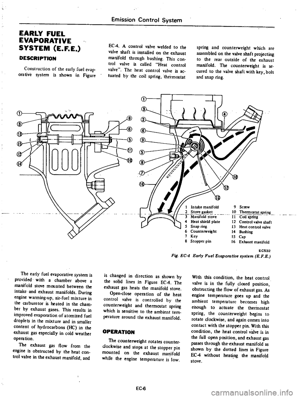
DESCRIPTION
spring
and
counterweight
which
are
assembled
on
the
valve
shaft
projecting
to
the
rear
outside
of
the
exhaust
manifold
The
counterweight
is
se
cured
to
the
valve
shaft
with
key
bolt
and
snap
ring
EC
4
A
control
valve
welded
to
the
valve
shaft
is
wtalled
on
the
exhaust
manifold
through
bushing
This
con
trol
valve
is
called
Heat
control
valve
The
heat
control
valve
is
ac
luated
by
the
coil
spring
thermostat
Construction
of
the
early
fuel
evap
orative
system
is
shown
in
Figure
r
I
1
@
rW
9
Sc
w
10
Thennostat
spring
11
Coil
spriiig
12
Control
valve
shaft
13
Heat
control
valve
14
Bushing
15
Cap
16
Exhaust
manifold
1
Intake
manifold
2
Stove
gasket
ManifoktstOve
4
Heat
shield
plate
5
Snap
ring
6
Counterweight
7
Key
g
Stoppel
pin
EC532
Fig
EC
4
Early
Fuel
Evaporutive
tem
E
F
E
The
early
fuel
evaporative
system
is
provided
with
a
chamber
above
a
manifold
stove
moonted
between
the
intake
and
exhaust
manifolds
During
engine
warming
up
air
fuel
mixture
in
the
carburetor
is
heated
in
the
cham
bet
by
exhaust
gases
This
results
in
improved
evaporation
of
atomized
fuel
droplets
in
the
mixture
and
in
smaller
content
of
hydrocarbons
He
in
the
exhaust
gas
especially
in
cold
weather
operation
The
exhaust
gas
flow
from
the
engine
is
obstructed
by
the
heat
con
trol
valve
in
the
exhaust
manifold
and
is
changed
in
direction
as
shown
by
the
solid
lines
in
Figure
EC
4
The
exhaust
gas
heats
the
manifold
stove
Open
close
operation
of
the
heat
control
valve
is
controlled
by
the
counterweight
and
thermostat
spring
which
is
sensitive
to
the
ambient
tem
perature
around
the
exhaust
manifold
With
this
condition
the
heat
control
valve
is
in
the
fully
closed
position
obstructing
the
flow
of
exhaust
gas
As
engine
tempera
lure
goes
up
and
the
ambient
temperature
becomes
high
enough
to
actuate
the
thermostat
spring
the
counterweight
begins
to
rotate
clockwise
and
again
comes
into
con
tact
with
the
stopper
pin
With
this
condition
the
heat
control
valve
is
in
the
full
open
position
and
exhaust
gas
passes
through
the
exhaust
manifold
as
shown
by
the
dotted
lines
in
Figure
EC
4
without
heati
ng
the
manifold
stove
OPERATION
The
counterweight
rotates
counter
clockwise
and
stops
at
the
stopper
pin
mounted
on
the
exhaust
manifold
while
the
engine
temperature
is
low
EC
6