air condition DATSUN PICK-UP 1977 Repair Manual
[x] Cancel search | Manufacturer: DATSUN, Model Year: 1977, Model line: PICK-UP, Model: DATSUN PICK-UP 1977Pages: 537, PDF Size: 35.48 MB
Page 219 of 537
Engine
Removal
Installation
ENGINE
REMOVAL
AND
INSTAllATION
REMOVAL
INSTALLATION
ENGINE
MOUNTING
INSULATORS
REMOVAL
It
is
much
easier
to
remove
engine
and
transmission
as
a
single
unit
than
to
remove
them
separately
After
re
moval
engine
can
be
separated
from
transntission
assembly
Notes
a
Be
sure
to
hoist
engine
and
jack
up
transmission
in
a
safe
manner
b
Use
fender
cove
to
protect
vehicle
body
1
Remove
battery
2
Scribe
hood
hinge
location
for
proper
reinstallation
and
remove
hood
Note
Have
an
assistant
help
you
so
as
to
prevent
damage
to
body
3
Drain
radiator
coolant
4
Disconnect
upper
and
lower
radiator
hoses
from
engine
5
Remove
two
oil
cooler
hoses
from
lower
end
of
radiator
Auto
ma
tic
transmission
models
only
6
Remove
radiator
shroud
7
Remove
four
bolts
securing
radia
tor
and
detach
radiator
Note
Always
tighten
securing
bolt
at
upper
right
hand
side
together
with
body
harness
terminal
8
Remove
carburetor
air
cleaner
as
follows
Remove
fresh
air
duct
Remove
hot
air
duct
Loosen
air
cleaner
band
bolt
and
air
cleaner
supporting
bolts
Disconnect
air
cleaner
ta
air
pump
hose
Disconnect
air
cleaner
to
rocker
cover
hose
at
rocker
cover
Disconnect
air
cleaner
to
air
control
valve
hose
California
models
only
CONTENTS
ER
2
ER
3
ER
3
FRONT
INSULATOR
REAR
INSULATOR
TIGHTENING
TORQUE
ER
4
ER
4
ER
4
Disconnect
air
deaner
to
A
B
valve
hose
Disconnect
air
cleaner
ta
vacuum
hoses
Note
Protect
carburetor
from
dust
and
foreign
matter
by
placing
cover
over
air
inlet
opening
9
Disconnect
fuel
pump
to
fuel
fdter
hose
and
return
hose
10
Disconnect
carbon
canister
hose
on
engine
side
II
Disconnect
air
pump
air
C1eaner
to
al
p
p
hose
12
Disconnect
following
cables
wires
and
hoses
Engine
ground
cable
Accelerator
wire
at
carburetor
High
tension
cable
between
ignition
coil
and
distributor
Wire
to
distributor
at
body
ter
minal
Wire
to
oil
pressure
switch
Wires
to
thermal
transmitter
Wires
to
B
C
p
D
cut
solenoid
Non
California
models
only
auto
choke
heater
and
anti
dieseling
solenoid
Wires
to
alternator
Wires
to
starter
motor
Heater
inlet
and
outlet
hoses
if
so
equipped
Vacuum
hose
of
Master
Vac
at
in
taJce
manifold
Wires
for
back
up
lamp
switch
Cable
to
speedometer
13
Remove
transmission
control
linkage
from
transmission
Manual
transmission
models
I
Detach
rubber
boot
2
Remove
E
ring
and
control
lever
pin
from
transmission
striking
rod
guide
and
remove
control
lever
ER
2
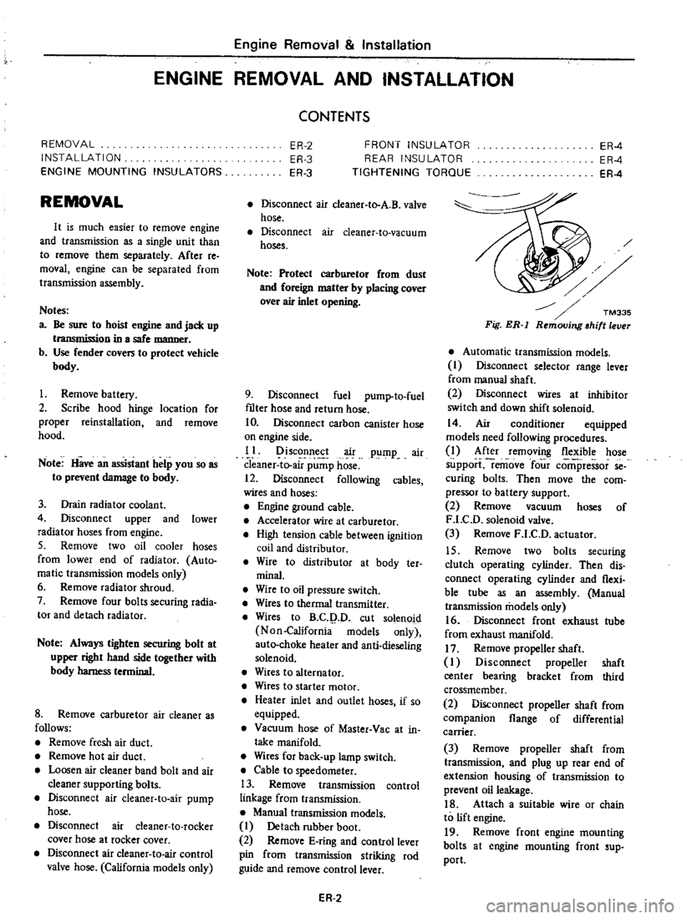
Fig
ER
l
Automatic
transmission
models
I
Disconnect
selector
range
lever
from
manual
shaft
2
Disconnect
wires
at
inhibitor
switch
and
down
shift
solenoid
14
Air
conditioner
equipped
models
need
following
procedures
1
After
removing
flexible
hose
support
remove
four
comi
ressor
se
curing
bolts
Then
move
the
com
pressor
to
battery
support
2
Remove
vacuum
hoses
of
F
LC
D
solenoid
valve
3
Remove
F
LC
D
actuator
15
Remove
two
bolts
securing
clutch
operating
cylinder
Then
dis
connect
operating
cylinder
and
flexi
ble
tube
as
an
assembly
Manual
transmission
models
only
16
Disconnect
front
exhaust
tube
from
exhaust
manifold
17
Remove
propeller
shaft
I
Disconnect
propeller
shaft
center
bearing
bracket
from
third
crossmember
2
Disconnect
propeller
shaft
from
companion
flange
of
differential
carrier
3
Remove
propeller
shaft
from
transmission
and
plug
up
rear
end
of
extension
housing
of
transmission
to
prevent
oil
leakage
18
Attach
a
suitable
wire
or
chain
to
lift
engine
19
Remove
front
engine
mounting
bolts
at
engine
mounting
front
sup
port
Page 231 of 537
CLUTCH
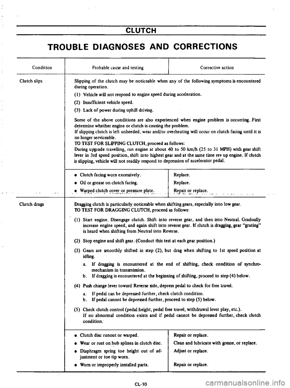
TROUBLE
DIAGNOSES
AND
CORRECTIONS
Condition
Probable
cause
and
testing
Clutch
slips
Corrective
action
Slipping
of
the
clutch
may
be
noticeable
when
any
of
the
following
symptoms
is
encountered
during
operation
I
Vehicle
will
not
respond
to
engine
speed
during
acceleration
2
Insufficient
vehicle
speed
3
Lack
of
power
during
uphill
driving
Some
of
the
above
conditions
are
also
experienced
when
engine
problem
is
oc
urring
First
de
tennine
whether
engine
or
clutch
is
causing
the
problem
If
slipping
clutch
is
left
unheeded
wear
and
or
overheating
will
occur
on
clutch
facing
until
it
is
no
longer
serviceable
TO
TEST
FOR
SLIPPING
CLlJfCH
proceed
as
follows
During
upgrade
travelling
run
engine
at
about
40
to
50
km
h
25
to
31
MPH
with
gear
shift
lever
in
3rd
speed
position
shift
into
highest
gear
and
at
the
same
time
rev
up
engine
If
clutch
is
slipping
vehicle
will
not
readily
respond
to
depression
of
accelerator
pedal
Clutch
facing
worn
excessively
Oil
or
grease
on
clutch
facing
W
r
d
clut
h
cov
r
pressure
plat
Replace
Replace
tpa
o
e
lace
Dragging
clutch
is
particularly
noticeable
when
shifting
gears
especially
into
low
gear
TO
TEST
FOR
DRAGGING
CLlJfCH
proceed
as
follows
I
Start
engine
Disengage
clutch
Shift
into
reverse
gear
and
then
into
Neutral
Gradually
increase
engine
speed
and
again
shift
into
reverse
gear
If
clutch
is
dragging
gear
grating
is
heard
when
shifting
from
Neutral
into
Reverse
Clutch
drags
2
Stop
engine
and
shift
gear
Conduct
this
test
at
each
gear
position
3
Gears
are
smoothly
shifted
in
step
2
but
drag
when
shifting
to
1st
speed
position
at
idling
a
If
dragging
is
encountered
at
the
end
of
shifting
check
condition
of
synchro
mechanism
in
transmission
b
If
dragging
is
encountered
at
the
beginning
of
shifting
proceed
to
step
4
below
4
Push
change
lever
toward
Reverse
side
depress
pedal
to
check
for
free
travel
a
If
pedal
can
be
depressed
further
check
clutch
condition
b
If
pedal
cannot
be
depressed
further
proceed
to
step
5
below
5
Check
clutch
control
pedal
height
pedal
free
travel
withdrawal
lever
play
etc
If
no
abnonnal
condition
exists
and
if
pedal
cannot
be
depressed
further
check
clutch
condition
Clutch
disc
runout
or
warped
Wear
or
rust
on
hub
splines
in
clutch
disc
Diaphragm
spring
toe
height
out
of
ad
justment
or
toe
tip
worn
Worn
or
improperly
installed
parts
CL10
Repair
or
replace
Clean
and
lubricate
with
grease
or
replace
Adjust
or
replace
Repair
or
replace
Page 232 of 537
Condition
Clutch
chatters
Noisy
clutch
Clutch
grabs
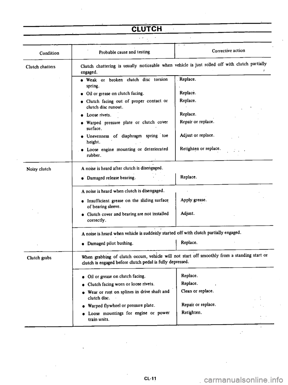
CLUTCH
Probable
cause
and
testing
Corrective
action
Clutch
chattering
is
usually
noticeable
when
vchicle
is
just
rolled
off
with
clutch
partially
engaged
Weak
or
broken
clutch
disc
torsion
spring
Oil
or
grease
on
clutch
facing
Clutch
facing
out
of
proper
contact
or
clutch
disc
runout
Loose
rivets
Warped
pressure
plate
or
clutch
cover
surface
Unevenness
of
diaphragm
spring
toe
height
Loose
engine
mounting
or
deteriorated
rubber
A
noise
is
heard
after
clutch
is
disengaged
Damaged
release
bearing
A
noise
is
heard
when
clutch
is
disengaged
Insufficient
grease
on
the
sliding
surface
of
bearing
sleeve
Clutch
cover
and
bearing
are
not
installed
correctly
Replace
Replace
Replace
Replace
Repair
or
replace
Adjust
or
replace
Retighten
or
replace
I
Replace
Apply
grease
Adjust
A
noise
is
heard
when
vehicle
is
suddei11y
staited
off
with
clutch
partially
engaged
Damaged
pilot
bushing
I
Replace
When
grabbing
of
clutch
occurs
vehicle
will
not
start
off
smoothly
from
a
standing
start
or
clutch
is
engaged
before
clutch
pedal
is
fully
depressed
Oil
or
grease
on
clutch
facing
Clutch
facing
worn
or
loose
rivets
Wear
or
rust
on
splines
in
drive
shaft
and
clu
tch
disc
Warped
flywheel
or
pressure
plate
Loose
mountings
for
engine
or
power
train
units
CLll
Replace
Replace
Clean
or
replace
Repair
or
replace
Retighten
Page 242 of 537
REAR
EXTENSION
DISASSEMBLY
Remove
lock
pin
from
striking
lever
and
remove
striking
rod
Manual
Transmission
Note
00
not
diSlssemble
rear
exten
sion
bush
from
rear
extension
ADAPTER
PLATE
DISASSEMBLY
I
Remove
six
6
bearing
retainer
attaching
screws
with
an
impact
wrench
and
remove
bearing
retainer
from
adapter
plate
2
Remove
reverse
idler
shaft
3
Remove
mainshaft
bearing
from
the
rear
extension
side
INSPECTION
Wash
all
parts
in
a
suitable
cleaning
solvent
and
check
for
wear
damage
or
other
faulty
conditions
Notes
a
Be
careful
not
to
damage
any
parts
with
scraper
b
00
not
clean
wash
or
soak
oil
seals
in
solvent
TRANSMISSION
CASE
AND
REAR
EXTENSION
HOUSING
I
Clean
with
solvent
thoroughly
and
check
for
cracks
which
might
cause
oil
leak
or
other
faulty
con
ditions
2
Check
mating
surface
of
the
case
to
engine
or
adapter
plate
for
small
nicks
projection
or
sealant
e
1
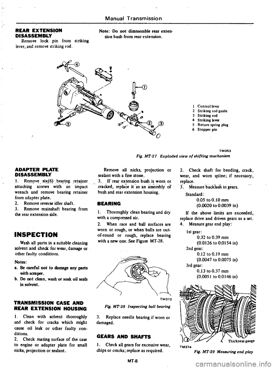
Control
lever
2
Striking
rod
guide
3
Striking
rod
4
Striking
lever
5
Return
spring
plug
6
Stopper
pin
TM353
Fig
MT
27
Exploded
view
of
shifting
mechani6m
Remove
all
nicks
projection
or
sealant
with
a
frne
stone
3
If
rear
extension
bush
is
worn
or
cracked
replace
it
as
an
assembly
of
bush
and
rear
extension
housing
BEARING
I
Thoroughly
clean
bearing
and
dry
with
a
compressed
air
2
When
race
and
ball
surfaces
are
worn
or
rough
or
when
balls
are
out
of
round
or
rough
replacebearihg
with
a
new
one
See
Figure
MT
28
I
TM372
Fig
MT
28
l
pecting
ball
bearing
3
Replace
needle
bearing
if
worn
or
damaged
GEARS
AND
SHAFTS
I
Check
all
gears
for
excessive
wear
chips
or
cracks
replace
as
required
MT
8
2
Check
shaft
for
bending
crack
wear
and
worn
spline
if
necessary
replace
3
Measure
backiasii
in
gears
Standard
0
05
to0
10mm
0
0020
to
0
0039
in
If
the
above
limits
are
exceeded
replace
drive
and
driven
gears
as
a
set
4
Measure
gear
end
play
1st
gear
0
32
to
0
39
mm
0
0126
to
0
0154
in
2nd
gear
0
12
to
0
19
mm
0
0047
to
0
0075
in
3rd
gear
0
13
to
0
37
mm
0
0051
to
0
0146
in
TM374
Fig
MT
29
Measuring
end
play
Page 253 of 537
ADAPTER
PLATE
DISASSEMBLY
Same
as
for
the
F4W71
B
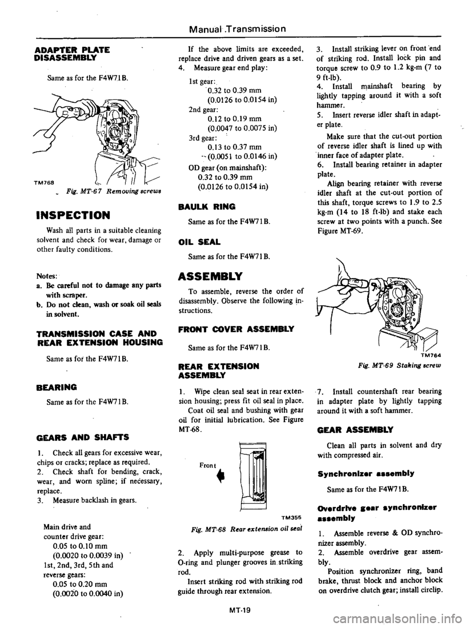
Fig
MT
67
Removing
screws
INSPECTION
Wash
all
parts
in
a
suitable
cleaning
solvent
and
check
for
wear
damage
or
other
faulty
conditions
Notes
a
Be
careful
not
to
damage
any
parts
with
scraper
b
Do
not
clean
wash
or
soak
oil
seals
in
solvent
TRANSMISSION
CASE
AND
REAR
EXTENSION
HOUSING
Same
as
for
the
F4W71
B
BEARING
Same
as
for
the
F4W7l
B
GEARS
AND
SHA
S
I
Check
all
gears
for
excessive
wear
chips
or
cracks
replace
as
required
2
Check
shaft
for
bending
crack
wear
and
worn
spline
if
necessary
replace
3
Measure
backlash
in
gears
Main
drive
and
counter
drive
gear
0
05
to
0
10
mm
0
0020
to
0
0039
in
1st
2nd
3rd
5th
and
reverse
gears
0
05
to
0
20
mm
0
0020
to
0
0040
in
Manual
Transmission
If
the
above
limits
are
exceeded
replace
drive
and
driven
gears
as
a
set
4
Measure
gear
end
play
1st
gear
0
32
to
0
39
mm
0
0126
to
0
0154
in
2nd
gear
0
12
to
0
19
mm
0
0047
to
0
0075
in
3rd
gear
0
13
to
0
37
mm
0
0051
to
0
0146
in
OD
gear
on
mainshaft
0
32
to
0
39
mm
0
0126
to
0
0154
in
BAULK
RING
Same
as
for
the
F4W7IB
OIL
SEAL
Same
as
for
the
F4W71
B
ASSEMBLY
To
assemble
reverse
the
order
of
disassembly
Observe
the
following
in
structions
FRONT
COVER
ASSEMBLY
Same
as
for
the
F4W7l
B
REAR
EXTENSION
ASSEMBLY
I
Wipe
clean
seal
seat
in
rear
exten
sion
housing
press
fit
oil
seal
in
place
Coat
oil
seal
and
bushing
with
gear
oil
for
initial
lubrication
See
Figure
MT
68
Front
r
I
TM355
Fig
MT
68
R
ar
extemion
oil
sea
2
Apply
multi
purpose
grease
to
O
ring
and
plunger
grooves
in
striking
rod
Insert
striking
rod
with
striking
rod
guide
through
rear
extension
MT19
3
Install
striking
lever
on
front
end
of
striking
rod
Install
lock
pin
and
torque
screw
to
0
9
to
1
2
kg
m
7
to
9
ft
lb
4
Install
filainshaft
bearing
by
lightly
tapping
around
it
with
a
soft
hammer
5
Insert
reverse
idler
shaft
in
adapt
er
plate
Make
sure
that
the
cut
out
portion
of
reverse
idler
shaft
is
lined
up
with
inner
face
of
adapter
plate
6
Install
bearing
retainer
in
adapter
plate
Align
bearing
retainer
with
reverse
idler
shaft
at
the
cut
out
portion
of
this
shaft
torque
screws
to
1
9
to
2
5
kg
m
14
to
18
ft
lb
and
stake
each
screw
at
two
points
with
a
punch
See
Figure
MT
69
TM764
Fig
MT
69
Stahing
screw
7
Install
countershaft
rear
bearing
in
adapter
plate
by
lightly
tapping
around
it
with
a
soft
hammer
GEAR
ASSEMBLY
Clean
all
parts
in
solvent
and
dry
with
compressed
air
Synchronlz
r
embly
Same
as
for
the
F4W71
B
Ov
rdrlve
r
ynchronlz
r
mbly
I
Assemble
reverse
OD
synchro
nizer
assembly
2
Assemble
overdrive
gear
assem
bly
Position
synchronizer
ring
band
brake
thrust
block
and
anchor
block
on
overdrive
clutch
gear
install
circlip
Page 257 of 537
Manual
Transmission
I
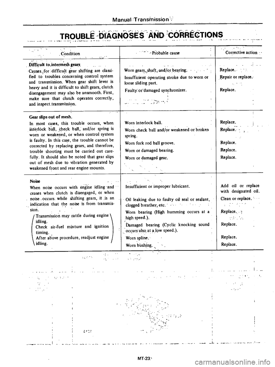
TROUBLE
DIAGNOSES
AND
CORREGTIONS
Condition
Difficult
to
intel11lesh
gears
Causes
Jor
difficu
t
gear
shifting
are
classi
fied
to
troubles
concerning
control
system
and
transniissioo
When
gear
shift
lever
is
heavy
and
it
is
difficult
to
shift
gears
clutch
disengagement
may
also
be
unsmooth
First
make
sure
that
clutch
operates
correctly
and
inspect
transmissi
o
Gear
slips
out
of
mesh
In
most
cases
this
trouble
occurs
when
interlock
b
all
check
ball
and
or
spring
is
worn
or
weakened
or
when
control
system
is
faulty
In
this
case
the
trouble
cannot
be
corrected
by
replacing
gears
and
therefore
trouble
shooting
must
be
carried
out
care
fully
It
should
also
be
noted
that
gear
slips
out
of
mesh
due
to
vibration
generated
by
weakened
fron
t
and
rear
engine
mounts
Noise
When
noise
occurs
with
engine
idling
and
ceases
when
clutch
is
disengaged
or
when
noise
occurs
while
shifting
gears
it
is
an
indicati90
that
th
e
noise
is
from
transmis
sion
t
Transmission
may
fa
ule
during
engine
idling
Check
air
fuel
mixture
and
ignition
timing
After
above
procedure
readjust
engine
idling
Probable
cause
Worn
gear
shaft
and
or
bearing
Insufficient
operating
stroke
due
to
worn
or
loose
sliding
part
Faulty
or
damaged
synchronizer
Worn
interlock
ball
Worn
check
ball
and
or
weakened
or
broken
spring
Wom
fork
rod
ball
groove
Wom
or
damaged
bearing
Worn
or
damaged
gear
Insufficient
or
improper
lubricant
Oil
leaking
due
to
faulty
oil
seal
or
sealant
clogged
breather
etc
Worn
bearing
High
humming
occurs
at
a
high
speed
Damaged
bearing
Cyclic
knocking
sound
occurs
also
at
a
19W
speed
Worn
spline
Worn
bushing
j
MT
23
Corrective
action
Replace
pair
or
replace
Replace
Replace
Replace
Replace
Replace
Replace
Add
oil
or
replace
with
designated
oil
Clean
Of
replace
Replace
Replace
Replace
Replace
Page 307 of 537
Automatic
Transmission
i
r
11
I
@
@
j
A
T290
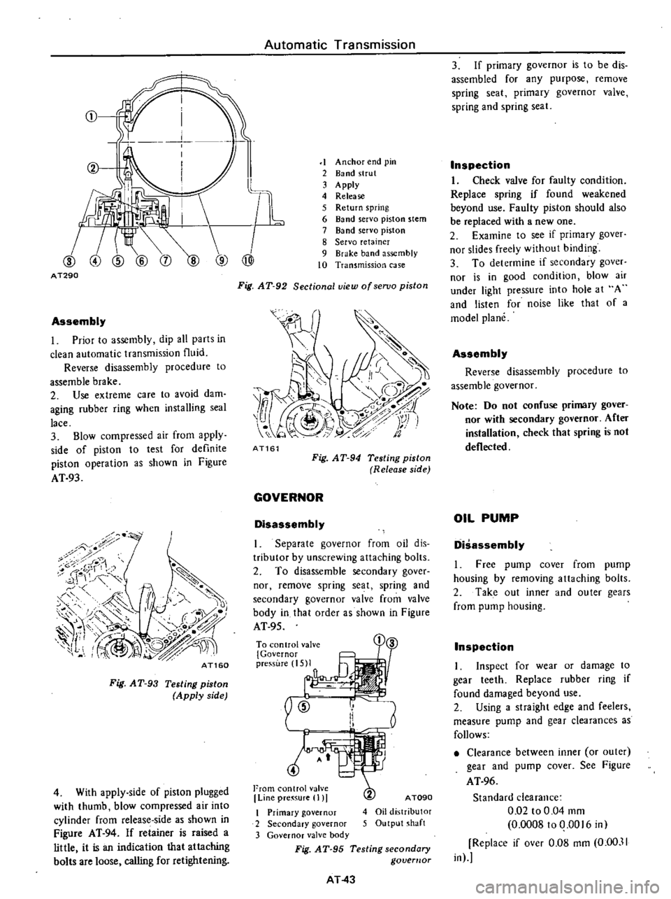
Assembly
I
Prior
to
assembly
dip
all
parts
in
clean
automatic
transmission
fluid
Reverse
disassembly
procedure
to
assemble
brake
2
Use
extreme
care
to
avoid
dam
aging
rubber
ring
when
installing
seal
lace
3
Blow
compressed
air
from
apply
side
of
piston
to
test
for
definite
piston
operation
as
shown
in
Figure
AT
93
7
i
8
ror
1
1
r
c
f
f
A
J
II
1
0
c
r
1
1
I
@
L
O
j
0
n
iJ
fl
IV
I
AT160
Fig
AT
93
Testing
piston
Apply
side
4
With
apply
side
of
piston
plugged
with
thumb
blow
compressed
air
into
cylinder
from
release
side
as
shown
in
Figure
AT
94
If
retainer
is
raised
a
little
it
is
an
indication
that
attaching
bolts
are
loose
calling
for
retightening
1
Anchor
end
pin
2
Band
strut
3
Apply
4
Release
5
Return
spring
6
Band
servo
piston
stem
7
Band
servo
piston
8
Servo
retainer
9
Brake
band
assembly
10
Transmission
case
Fig
AT
92
Sectional
view
ofseruo
piston
7
o
i
J
1S
I
z
1
Y
i
1
t
9
c
fa
AT161
Fig
AT
94
Testing
piston
Release
side
GOVERNOR
Disassembly
I
Separate
governor
from
oil
dis
tributor
by
unscrewing
attaching
bolts
2
To
disassemble
secondary
gover
nor
remove
spring
seat
spring
and
secondary
governor
valve
from
valve
body
in
that
order
as
shown
in
Figure
AT
95
To
control
val
i
1
3
5MI
n
ID
r
Ii
I
4
From
control
valve
Line
pre
sure
I
I
A
TOgO
4
Oil
distributor
5
Output
shaft
I
Primary
governor
2
Secondary
governor
3
Governor
valve
body
Fig
AT
95
Testing
secondary
govemor
AT
43
3
If
primary
governor
is
to
be
dis
assembled
for
any
purpose
remove
spring
seat
primary
governor
valve
spring
and
spring
seat
Inspection
I
Check
valve
for
faulty
condition
Replace
spring
if
found
weakened
beyond
use
Faulty
piston
should
also
be
replaced
with
a
new
one
2
Examine
to
see
if
primary
gover
nor
slides
freely
without
binding
3
To
determine
if
secondary
gaver
nor
is
in
good
condition
blow
air
under
light
pressure
into
hole
at
A
and
listen
for
noise
like
that
of
a
model
plane
Assembly
Reverse
disassembly
procedure
to
assemble
governor
Note
Do
not
confuse
primary
gover
nor
with
secondary
governor
After
installation
check
that
spring
is
not
deflected
OIL
PUMP
Disassembly
I
Free
pump
cover
from
pump
housing
by
removing
attaching
bolts
2
Take
out
inner
and
outer
gears
from
pump
housing
Inspection
I
Inspect
for
wear
or
damage
to
gear
teeth
Replace
rubber
ring
if
found
damaged
beyond
use
2
Using
a
straight
edge
and
feelers
measure
pump
and
gear
clearances
as
follows
Clearance
between
inner
or
outer
gear
and
pump
cover
See
Figure
AT
96
Standard
clearance
0
02
to
0
04
mm
0
0008100
0016
in
Replace
if
over
0
08
mm
0
00
11
in
Page 312 of 537
Automatic
Transmission
TROUBLE
DIAGNOSIS
AND
ADJUSTMENT
INSPECTION
AND
ADJUSTMENT
BEFORE
TRQUBLE
DIAGNOSIS
TESTING
INSTRUMENT
FOR
INSPECTION
CHECKING
OIL
LEVEL
INSPECTION
AND
REPAIR
OF
OIL
EAKAGE
CHECKING
ENGINE
IDLING
REVOLUTION
CHECKING
AND
ADJUSTING
KICKDOWN
SWITCH
AND
DqWNSHIFT
SOLENOID
N
J
J
CII
Q
t
L
8li
p
JYSTMs
T
OF
MANUAL
LINKAGE
CHECKING
AND
ADJUSTING
INHIBITOR
SWITCH
STALL
TEST
STALL
TEST
PROCEDURES
JUDGEMENT
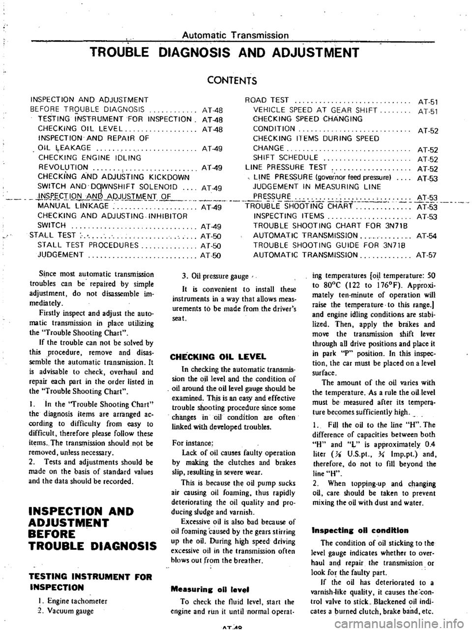
Since
most
automatic
transmission
troubles
can
be
repaired
by
simple
adjustment
do
not
disassemble
im
mediately
Firstly
inspect
and
adjust
the
auto
matic
transmission
in
place
utilizing
the
Trouble
Shooting
Chart
If
the
trouble
can
not
be
solved
by
this
procedure
remove
and
disas
semble
the
automatic
transmission
It
is
advisable
to
check
overhaul
and
repair
each
part
in
the
order
listed
in
the
Trouble
Shooting
Chart
I
In
the
Trouble
Shooting
Chart
the
diagnosis
items
are
arranged
ac
cording
to
difficulty
from
easy
to
difficult
therefore
please
follow
these
items
The
transmission
should
not
be
removed
unless
necessary
2
Tests
and
adjustments
should
be
made
on
the
basis
of
standard
values
and
the
data
should
be
recorded
INSPECTION
AND
ADJUSTMENT
BEFORE
TROUBLE
DIAGNOSIS
TESTING
INSTRUMENT
FOR
INSPECTION
I
Engine
tachometer
2
Vacuum
gauge
ROAD
TEST
VEHICLE
SPEED
AT
GEAR
SHIFT
CHECKING
SPEED
CHANGING
CONDITION
CHECKING
ITEMS
DURING
SPEED
CHANGE
SHIFT
SCHEDULE
LINE
PRESSURE
TEST
LINE
PRESSURE
governor
feed
pressure
JUDGEMENT
IN
MEASURING
LINE
PRESSURE
At
49
TR6
uBLE
SHOOTINC
CHART
INSPECTING
ITEMS
TROUBLE
SHOOTING
CHART
FOR
3N71B
AUTOMATIC
TRANSMISSION
TROUBLE
SHOOTING
GUIDE
FOR
3N71B
AUTOMATIC
TRANSMISSION
CONTENTS
AT
4B
AT
48
AT
4B
AT
49
AT
49
AT
49
AT
49
AT
50
AT
50
AT
50
3
Oil
pressure
gauge
It
is
convenient
to
install
these
instruments
in
a
way
that
allows
meas
urements
to
be
made
from
the
driver
s
seat
CHECKING
OIL
LEVEL
In
checking
the
automatic
transmis
sion
the
o
illevel
and
the
condition
of
oil
around
the
oil
level
gauge
should
be
examined
This
is
an
easy
and
effective
trouble
shooting
procedure
since
some
changes
in
oil
condition
are
often
linked
with
developed
troubles
For
instance
Lack
of
oil
causes
faulty
operation
by
making
the
clutches
and
brakes
slip
resulting
in
severe
wear
This
is
because
the
oil
pump
sucks
air
causing
oil
foaming
thus
rapidly
deteriorating
the
oil
quality
and
pro
ducing
sludge
and
varnish
Excessive
oil
is
also
bad
because
of
oil
foaming
caused
by
the
gears
stirring
up
the
oil
During
high
speed
driving
excessive
oil
in
the
transmission
often
blows
out
from
the
breather
Measuring
011
level
To
check
the
fluid
level
start
the
engine
and
run
it
until
normal
operat
T
AO
AT
51
AT
51
AT
52
AT
52
AT
52
AT
52
AT
53
AT
3
AT
53
AT
53
AT
54
AT
57
ing
temperatures
o
temperature
SO
to
800C
122
to
l760F
Approxi
mately
ten
minute
of
operation
will
raise
the
temperature
to
this
range
and
engine
idling
conditions
are
stabi
lized
Then
apply
the
brakes
and
move
the
transmission
shift
lever
through
all
drive
positions
and
place
it
in
park
P
position
In
this
inspec
tion
the
car
must
be
placed
on
a
level
surface
The
amount
of
the
oil
varies
with
the
temperature
As
a
rule
the
oil
level
must
be
measured
after
its
temper
ture
becomes
sufficiently
high
1
Fill
the
oil
to
the
line
H
The
difference
of
capacities
between
both
H
and
L
is
approximately
0
4
liter
Ji
V
S
p
Y
Imp
pl
and
therefore
do
not
to
fill
beyond
the
line
H
2
When
topping
up
and
changing
oil
care
should
be
taken
to
prevent
mixing
the
oil
with
dust
and
water
InspectIng
011
condition
The
condition
of
oil
sticking
to
the
level
gauge
indicates
whether
to
over
haul
and
repair
the
transmission
or
look
for
the
faulty
part
If
the
oil
has
deteriorated
to
a
varnish
ike
quality
it
causes
the
con
trol
valve
to
stick
Blackened
oil
indi
cates
a
burned
clutch
brake
band
etc
Page 336 of 537
PROPElli
ER
SHAfT
DIFFERENTIAL
G
ARRIERf
Notes
a
PUller
should
be
handled
with
care
in
catchins
the
edge
of
bearing
inner
race
b
Be
careful
not
to
confuse
left
and
right
hand
parts
2
Remove
ring
gear
by
spreading
out
lock
strap
and
loosening
ring
gear
bolts
in
diagonally
3
Punch
off
pinion
mate
shaft
lock
pin
from
ring
gear
side
using
Solid
Punch
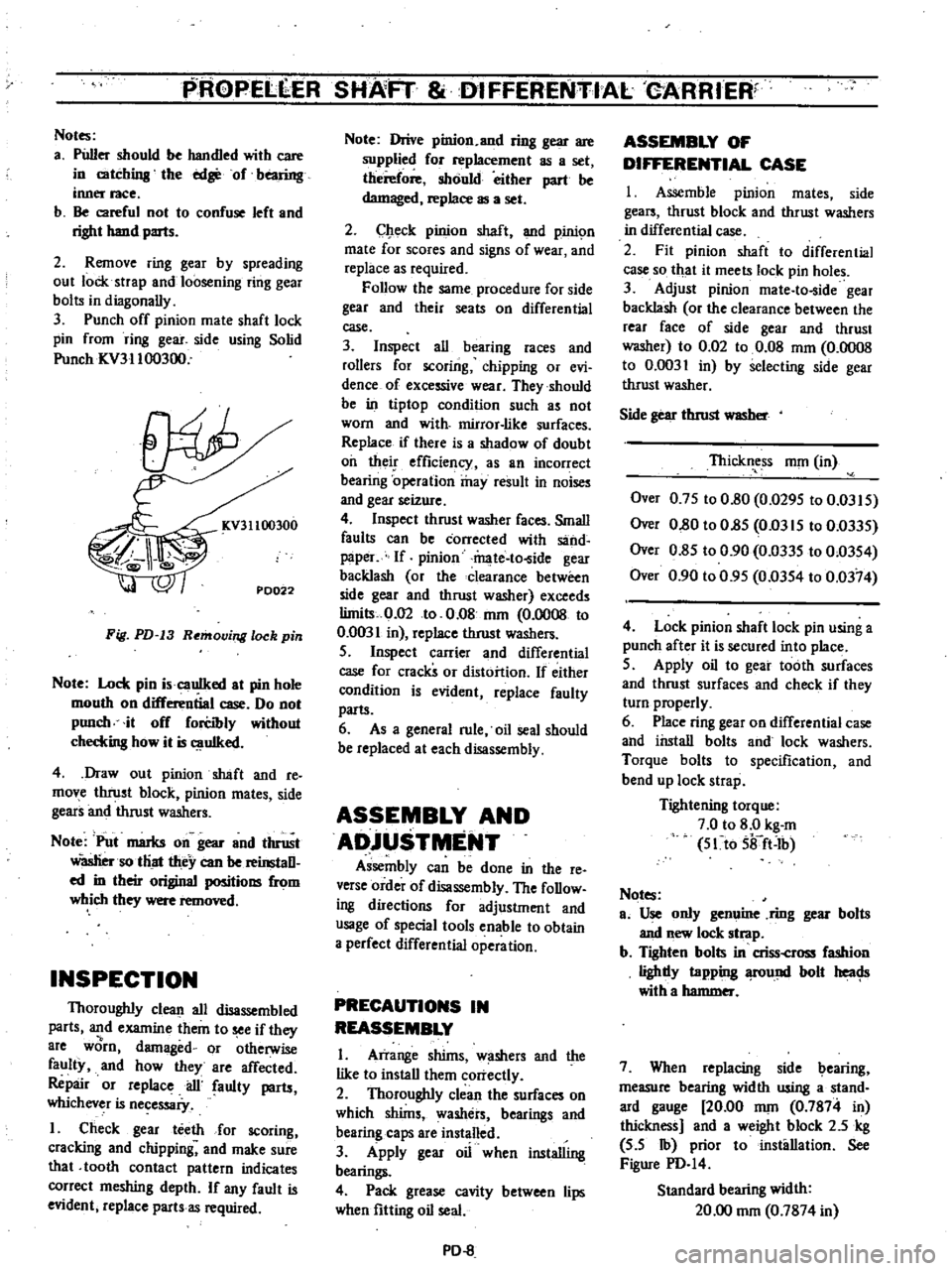
ICV31100300
KV31100300
PD022
Fig
PD
13
Removing
lock
pin
Note
Lock
pin
i
cauIked
at
pin
hole
mouth
on
differential
case
Do
not
punch
it
off
forCibly
without
checkins
how
it
is
uIked
4
Draw
out
pinion
shaft
and
re
move
thrust
block
pinion
mates
side
gears
and
thrust
washers
Note
Put
marks
on
gear
and
thrust
Wasliersotliat
they
can
be
reinstaD
ed
in
their
original
positions
from
which
they
were
removed
INSPECTION
Thoroughly
clean
all
disassembled
parts
and
examine
them
to
see
if
they
8re
worn
damaged
or
otherwise
faulty
and
how
they
are
affected
Repair
or
replace
ail
faulty
parts
whichever
is
necessaiy
I
Check
gear
teeth
for
scoring
cracking
and
chipping
and
make
sure
that
tooth
contact
pattern
indicates
correct
meshing
depth
If
any
fault
is
evident
replace
parts
as
required
Note
Drive
pinion
and
ring
gear
are
supplied
for
replacement
as
a
set
therefore
should
either
part
be
damaged
replace
as
a
set
2
Check
pinion
shaft
and
pinic
m
mate
for
scores
and
signs
of
wear
and
replace
as
required
Follow
the
same
procedure
for
side
gear
and
their
seats
on
differential
case
3
Inspect
all
bearing
races
and
rollers
for
scoring
chipping
or
evi
dence
of
excessive
wear
They
should
be
in
tiptop
condition
such
as
not
worn
and
with
mirror
like
surfaces
Replace
if
there
is
a
shadow
of
doubt
oil
their
efficiency
as
an
incorrect
bearing
operation
may
result
in
noises
and
gear
seizure
4
Inspect
thrust
washer
faces
Small
faults
can
be
corrected
with
sand
paper
If
pinion
mate
to
ide
gear
backlash
or
the
clearance
between
side
gear
and
thrust
washer
exceeds
limits
0
02
to
0
08
nun
0
0008
to
0
0031
in
replace
thrust
washers
S
Inspect
carrier
and
differential
case
for
cracks
or
distortion
If
either
condition
is
evident
replace
faulty
parts
6
As
a
general
rule
oil
seal
should
be
replaced
at
each
disassembly
ASSEMBLY
AND
ADjUSTMENT
Assembly
can
be
done
in
the
reo
verse
order
of
disassembly
The
foDow
ing
directions
for
adjustment
and
usage
of
special
tools
enable
to
obtain
a
perfect
differential
operation
PRECAUTIONS
IN
REASSEMBLY
I
Arrange
shims
w
shers
and
the
like
to
install
them
correctly
2
Thoroughly
clean
the
surfaces
on
which
shims
washers
bearings
and
bearing
caps
are
installed
3
Apply
gear
oil
when
installing
bearings
4
Pack
grease
cavity
between
lips
when
fitting
oil
seal
PD
8
ASSEMBLY
OF
DIFFERENTIAL
CASE
I
Assemble
pinion
mates
side
gears
thrust
block
and
thrust
washers
in
differential
case
2
Fit
pinion
shaft
to
differential
case
so
that
it
meets
lock
pin
holes
3
Adjust
pinion
mate
to
ide
gear
backlash
or
the
clearance
between
the
rear
face
of
side
gear
and
thrust
washer
to
0
02
to
0
08
mOl
0
0008
to
0
0031
in
by
selecting
side
gear
thrust
washer
Side
gear
thrust
WlISber
Thickness
nun
in
Over
0
7S
to
0
80
0
029S
to
0
03IS
Over
0
80
to
O
8S
Om
IS
to
0
033S
Over
0
8S
to
0
90
0
033S
to
0
03S4
Over
0
90
to
0
9S
0
03S4
to
0
0374
4
Lock
pinion
shaft
lock
pin
using
a
punch
after
it
is
secured
into
place
S
Apply
oil
to
gear
tooth
surfaces
and
thrust
surfaces
and
check
if
they
turn
properly
6
Place
ring
gear
on
differential
case
and
install
bolts
and
lock
washers
Torque
bolts
to
specification
and
bend
up
lock
strap
Tightening
torque
7
0
to
8
0
kg
m
S1to
Sifft
Ib
Notes
ao
Use
only
genuine
ring
gear
bolts
and
new
lock
strap
b
Tighten
bolts
in
criss
cross
fashion
lighdy
tapping
fOund
bolt
heac
Js
with
a
hammer
7
When
replacing
side
bearing
measure
bearing
width
using
a
stand
ard
gauge
20
00
nun
0
7874
in
thickness
and
a
weight
block
2
5
kg
S
S
Ib
prior
to
installation
See
Figure
PD
I4
Standard
bearing
width
20
00
nun
0
7874
in
Page 342 of 537
PROPELLER
SHAFT
DIFFERENTIAl
CARRIER
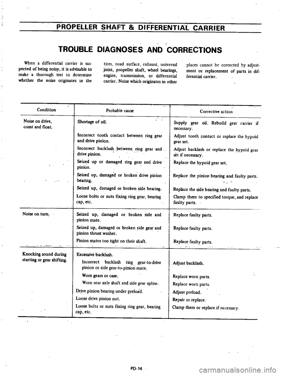
TROUBLE
DIAGNOSES
AND
CORRECTIONS
When
a
differential
carrier
is
sus
pected
of
being
noisy
it
is
advisable
to
make
a
thorough
lest
to
determine
whether
the
noise
originates
in
the
Condition
Noise
on
drive
coast
and
float
Noise
on
turn
Knocking
sound
during
starting
or
gear
shifting
tires
road
surface
exhaust
universal
joint
propeller
shaft
wheel
bearings
engine
transmission
or
differential
carrier
Noise
which
originates
in
other
Probable
cause
Shortage
of
oil
Incorrect
tooth
contact
between
ring
gear
and
drive
pinion
Incorrect
backlash
between
ring
gear
and
drive
pinion
Seized
up
or
damaged
ring
gear
and
drive
pinion
Seized
up
damaged
or
broken
drive
pinion
bearing
Seized
up
damaged
or
broken
side
bearing
Loose
bolts
or
nuts
fIXing
ring
gear
bearing
cap
etc
Seized
up
damaged
or
broken
side
and
pinion
mate
Seized
up
damaged
or
broken
side
gear
and
pinion
thrust
washer
Pinion
mates
too
tight
on
their
shaft
Excessive
backlash
Incorrect
backlash
ring
ar
to
drive
pinion
or
side
gear
to
pinionmate
Worn
gears
or
case
Worn
rear
axle
shaft
and
side
gear
spline
Drjve
pinion
bearing
under
p
reload
Loose
drive
pinion
nut
Loose
bolts
or
nuts
ftxing
ring
gear
bearing
cap
etc
PD
14
places
cannot
be
corrected
by
adjust
ment
or
replacement
of
parts
in
dif
ferential
carrier
Corrective
action
Supply
gear
oil
Rebuild
gear
carrier
if
necessary
Adjust
tooth
contact
or
replace
the
hypoid
gear
set
Adjust
backlash
or
replace
the
hypoid
gear
set
if
necessary
Replace
the
hypoid
gear
set
Replace
the
pinion
bearing
and
faulty
parts
Replace
the
side
bearing
and
faulty
parts
Clamp
them
to
specified
torque
and
replace
faulty
parts
Replace
faulty
parts
Replace
faulty
parts
Replace
faulty
parts
Adjust
backlash
Replace
worn
parts
Replace
worn
parts
Adjust
preload
Repair
or
replace
Clamp
them
or
replace
if
necessary