battery DATSUN PICK-UP 1977 Workshop Manual
[x] Cancel search | Manufacturer: DATSUN, Model Year: 1977, Model line: PICK-UP, Model: DATSUN PICK-UP 1977Pages: 537, PDF Size: 35.48 MB
Page 461 of 537
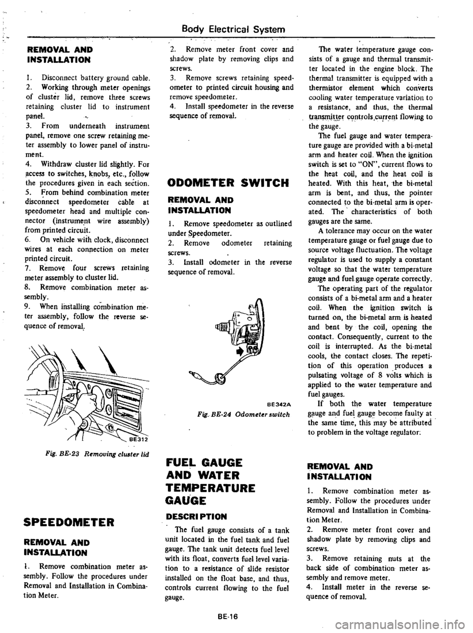
REMOVAL
AND
INSTALLATION
I
Disconnect
battery
ground
cable
2
Working
through
meter
openings
of
cluster
lid
remove
three
screws
retaining
cluster
lid
to
instrument
panel
3
From
underneath
instrument
panel
remove
one
screw
retaining
me
ter
assembly
to
lower
panel
of
instru
ment
4
Withdraw
cluster
lid
slightly
For
ccess
to
switches
knobs
etc
follow
the
procedures
given
in
each
section
5
From
behind
combination
meter
disconnect
speedometer
cable
at
speedometer
head
and
multiple
con
nector
instrume
nt
wire
assembly
from
printed
circuit
6
On
vehicle
with
clock
disconnect
wires
at
each
connection
on
meter
printed
circuit
7
Remove
four
screws
retaining
me
ter
assembly
to
cluster
lid
8
Remov
combination
meter
as
sembly
9
When
installing
combination
me
ter
assembly
follow
the
reverse
se
quence
of
removal
Fig
BE
23
Removing
eluster
lid
SPEEDOMETER
REMOVAL
AND
INSTALLATION
1
Remove
combination
meter
as
sembly
Follow
the
procedures
under
Removal
and
Installation
in
Combina
tion
Meter
Body
Electrical
System
2
Remove
meter
front
cover
and
shadow
plate
by
removing
clips
and
screws
3
Remove
screws
retaining
speed
ometer
to
printed
circuit
housing
and
remove
speedometer
4
Install
speedometer
in
the
reverse
sequence
of
removal
ODOMETER
SWITCH
REMOVAL
AND
INSTALLATION
I
Remove
speedometer
as
outlined
under
Speedometer
2
Remove
odometer
retaining
screws
3
Install
odometer
in
the
reverse
sequence
of
removal
BE342A
Fig
BE
24
Odometerswitch
FUEL
GAUGE
AND
WATER
TEMPERATURE
GAUGE
DESCRI
PTION
The
fuel
gauge
consists
of
a
tank
unit
located
in
the
fuel
tank
and
fuel
gauge
The
tank
unit
detects
fuel
level
with
its
float
converts
fuel
level
varia
tion
to
a
resistance
of
slide
resistor
installed
on
the
float
base
and
thus
controls
current
flowing
to
the
fuel
gauge
BE16
The
water
temperature
gauge
con
sists
of
a
gauge
and
thermal
transmit
ter
located
in
the
engine
block
The
thermal
transmitter
is
equipped
with
a
thermistor
element
which
converts
cooling
water
temperature
variation
to
a
resistance
and
thus
the
thermal
tr
t
c
rtrols
cUfTent
flowing
to
the
gauge
The
fuel
gauge
and
water
tempera
ture
gauge
are
provided
with
a
bi
metal
arm
and
heater
coil
When
the
ignition
switch
is
set
to
ON
current
flows
to
the
heat
coil
and
the
heat
coil
is
heated
With
this
heat
the
bi
metal
arm
is
bent
and
thus
the
pointer
connected
to
the
bi
metal
arm
is
oper
ated
The
characteristics
of
both
gauges
are
the
same
A
tolerance
may
occur
on
the
water
temperature
gauge
or
fuel
gauge
due
to
source
voltage
fluctuation
The
voltage
regulator
is
used
to
supply
a
constant
voltage
so
that
the
water
temperature
gauge
and
fuel
gauge
operate
correctly
The
operating
part
of
the
regulator
consists
of
a
bi
metal
arm
and
a
heater
coil
When
the
ignition
switch
is
turned
on
the
bi
metal
arm
is
heated
and
bent
by
the
coil
opening
the
contact
Consequently
current
to
the
coil
is
interrupted
As
the
bi
metal
cools
the
contact
closes
The
repeti
tion
of
this
operation
produces
a
pulsating
voltage
of
8
volts
which
is
applied
to
the
water
temperature
and
fuel
gauges
If
both
the
water
temperature
gauge
and
fuel
gauge
become
faulty
at
the
same
time
this
may
be
attributed
to
problem
in
the
voltage
regulator
REMOVAL
AND
INSTALLATION
1
Remove
combination
meter
as
sembly
Follow
the
procedures
under
Removal
and
Installation
in
Combina
tion
Meter
2
Remove
meter
front
cover
and
shadow
plate
by
removing
clips
and
screws
3
Remove
retaining
nuts
at
the
back
side
of
combination
meter
as
sembly
and
remove
meter
4
Install
meter
in
the
reverse
se
quence
of
removal
Page 462 of 537
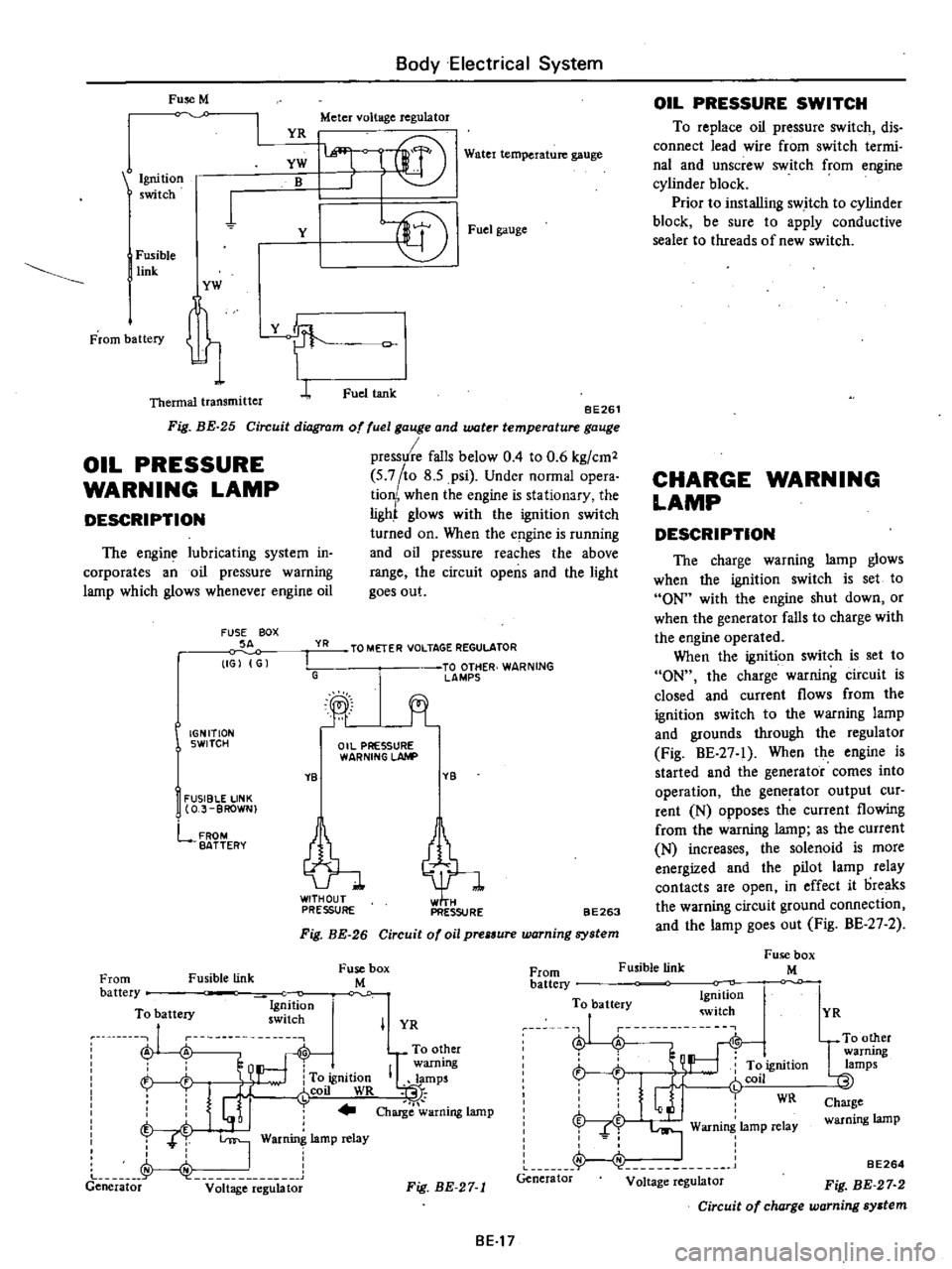
Fuse
M
Body
Electrical
System
YR
Meter
voltage
regulator
Water
temperature
gauge
BE261
Circuit
diagram
of
fuel
gauge
and
water
temperature
gauge
pressure
falls
below
0
4
to
0
6
kg
cm2
5
7
to
8
5
psi
Under
normal
opera
tion
when
the
engine
is
stationary
the
ligh
glows
with
the
ignition
switch
turned
on
When
the
e
gine
is
running
and
oil
pressure
reaches
the
above
range
the
circuit
opens
and
the
light
goes
out
Ignition
switch
YW
B
1
Y
I
Fusible
link
YW
t
Thermal
transmitter
L
Fig
BE
25
OIL
PRESSURE
WARNING
LAMP
DESCRIPTION
The
engine
lubricating
system
in
corporates
an
oil
pressure
warning
lamp
which
glows
whenever
engine
oil
FUSE
BOX
SA
IGJ
G
YR
I
G
IGNITION
SWITCH
YB
I
FUSIBLE
LINK
O
J
BROWN
lffi
l
f
r@
Fuel
gauge
Fuel
tank
TO
METER
VOLTAGE
REGULATOR
TO
OTHER
WARNING
lAMPS
jt
Oil
PRESSURE
WARNING
LAhlP
YB
tl
PRESSURE
PRESSURE
FROM
BATTERY
BE263
Fig
BE
26
Circuit
of
oil
prelSure
warning
system
Fusible
link
Fuse
box
M
OIL
PRESSURE
SWITCH
To
replace
oil
pressure
switch
dis
connect
lead
wire
from
switch
termi
nal
and
unscrew
switch
from
engine
cylinder
block
Prior
to
installing
switch
to
cylinder
block
be
sure
to
apply
conductive
sealer
to
threads
of
new
switch
CHARGE
WARNING
LAMP
DESCRIPTION
The
charge
warning
lamp
glows
when
the
ignition
switch
is
set
to
ON
with
the
engine
shut
down
or
when
the
generator
falls
to
charge
with
the
engine
operated
When
the
ignition
switch
is
set
to
ON
the
charge
warning
circuit
is
closed
and
current
flows
from
the
ignition
switch
to
the
warning
lamp
and
grounds
through
the
regulator
Fig
BE
27
1
When
the
engine
is
started
and
the
generator
comes
into
operation
the
generator
output
cur
rent
N
opposes
th
current
flowing
from
the
warning
lamp
as
the
current
N
increases
the
solenoid
is
more
energized
and
the
pilot
lamp
relay
contacts
are
open
in
effect
it
oreaks
the
warning
circuit
ground
connection
and
the
lamp
goes
out
Fig
BE
27
2
Fusible
link
Fuse
box
M
From
battery
To
battery
Ig
ition
ru
nu
swllch
A
A
To
other
warning
h
To
ignition
IQlamps
i
J
r
coil
WR
t
I
j
Charge
warning
lamp
T
T
I
War
lamp
relay
J
I
Generator
v
it
ge
e
g
bt
From
battery
To
battery
Ignition
witch
J
i
L
r
t
ft
ignition
r
Glj
fCOil
WR
f
I
Warning
lamp
relay
Generator
Voltage
regulator
I
YR
Fig
BE
27
1
BE17
YR
UTO
other
warrung
lamps
Charge
warning
lamp
BE264
Fig
BE
27
2
Circuit
of
charge
warning
system
Page 463 of 537
HAND
BRAKE
WARNING
LAMP
DESCRIPTION
The
hand
brake
warning
lamp
glows
when
the
hand
brake
is
applied
When
the
ignition
switch
is
set
to
ON
current
flows
from
the
ignition
switch
to
the
warning
lamp
When
the
hand
brake
is
applied
hand
brake
warning
switch
is
closed
and
warning
lamp
glows
Fuse
M
Ignition
5
tch
Fusible
link
From
battery
I
YG
1
1
Hand
brake
sWitch
BE314
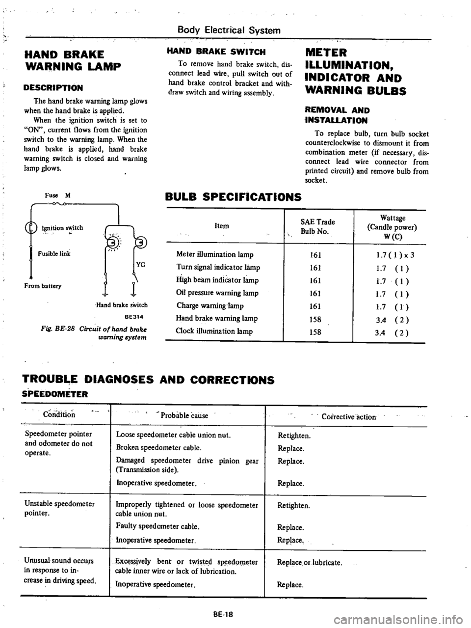
Fig
BE
28
Circuit
of
hand
broke
warning
Iystem
Body
Electrical
System
HAND
BRAKE
SWITCH
To
remove
hand
brake
switch
dis
connect
lead
wire
pull
switch
out
of
hand
brake
control
bracket
and
with
draw
switch
and
wiring
assembly
METER
ILLUMINATION
INDICATOR
AND
WARNING
BULBS
REMOVAL
AND
INSTALLATION
To
replace
bulb
turn
bulb
socket
counterclockwise
to
dismount
it
from
combination
meter
if
necessary
dis
connect
lead
wire
connector
from
printed
circuit
and
remove
bulb
from
socket
BULB
SPECIFICATIONS
Item
Meter
illumination
lamp
Turn
signal
indicator
lamp
High
beam
indicator
lamp
Oil
pressure
warning
lamp
Charge
warning
lamp
Hand
brake
warning
lamp
Clock
illumination
lamp
SAE
Trade
Bulb
No
Wattage
Candle
power
W
e
161
161
161
161
161
158
158
1
7
I
x3
1
7
I
1
7
I
I
7
I
1
7
I
3
4
2
3
4
2
TROUB
E
DIAGNOSES
AND
CORRECTIONS
SPEEDOMETER
Condition
Speedometer
pointer
and
odometer
do
not
operate
Unstable
speedometer
pointer
Unusual
sound
occurs
in
response
to
in
crease
in
driving
speed
Probable
cause
Loose
speedometer
cable
union
nut
Broken
speedometer
cable
Damaged
speedometer
drive
pinion
gear
Transmission
side
Inoperative
speedometer
Improperly
tightened
or
loose
speedometer
cable
union
nut
Faulty
speedometer
cable
Inoperative
speedometer
ExceS
jvelybent
or
twisted
speedOmeter
cable
inner
wire
or
lack
of
lubrication
Inoperative
speedometer
8El8
Coirective
action
Retighten
Replace
Replace
Replace
Retighten
Replace
Replace
Replace
or
lubricate
Replace
Page 466 of 537
Body
Electrical
System
ELECTRICAL
ACCESSORIES
CONTENTS
HORN
DESCRIPTION
REMOVAL
AND
INSTALLATION
IGNITION
SWITCH
REMOVAL
AND
INSTALLATION
INSPECTION
WINDSHIELD
WIPER
AND
WASHER
REMOVAL
AND
INSTALLATION
INSPECTION
RADIO
REMOVAL
AND
INSTALLATION
ADJUSTMENT
CLOCK
REMOVAL
I
NST
ALLA
TION
HEATER
DESCRIPTION
AIRFLOW
HEATER
UNIT
ASSEMBLY
BE
21
BE
21
BE
21
8E
n
BE
22
BE
22
BE
23
BE
23
BE
23
BE
25
BE
25
BE
25
BE
25
BE
25
BE
26
BE
26
BE
26
BE
28
BE
29
HORN
DESCRIPTION
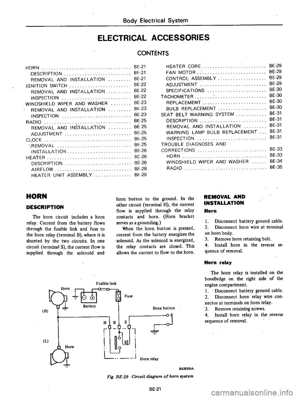
The
horn
circuit
includes
a
horn
relay
Current
from
the
battery
flows
through
the
fusible
link
and
fuse
to
the
horn
relay
terminal
B
where
it
is
shunted
by
the
two
circuits
In
one
circuit
terminal
S
the
current
flow
is
supplied
through
the
solenoid
and
Fusible
link
Qi
att
Fu
H
I
HIBQ
t
J
JJI
L
J
Hornrelay
Qm
HEATER
CORE
FAN
MOTOR
CONTROL
ASSEMBLY
ADJUSTMENT
SPECIFICATIONS
TACHOMETER
REPLACEMENT
8UL8
REPLACEMENT
SEAT
8ELT
WARNING
SYSTEM
DESCRIPTION
REMOVAL
AND
INSTALLATION
WARNING
LAMP
BULB
REPLACEMENT
INSPECTION
TROUBLE
DIAGNOSES
AND
CORRECTIONS
HORN
WINDSHIELD
WIPER
AND
WASHER
RADIO
Horn
button
BE859A
Fig
BE
29
Circuit
diagram
of
horn
sy
tem
horn
button
to
the
ground
In
the
other
circuit
terminal
H
the
current
flow
is
supplied
through
the
relay
contacts
and
horn
Horn
bracket
serves
as
a
grounding
When
the
horn
button
is
pressed
current
from
the
battery
energizes
the
solenoid
As
the
solenoid
is
energized
the
relay
contacts
are
closed
This
allows
the
current
to
flow
to
the
horn
BE
21
REMOVAL
AND
INSTALLATION
Horn
8E
29
BE
29
BE
29
8E
29
BE
30
BE
30
BE
30
8E
30
8E
31
BE
31
BE
31
8E
31
8E
31
BE
33
8E
33
8E
34
BE
35
I
Disconnect
battery
ground
cable
2
Disconnect
horn
wire
at
terminal
on
horn
body
3
Remove
horn
retaining
bolt
4
Install
horn
in
the
reverse
se
quence
of
removal
Horn
relay
The
horn
relay
is
installed
on
the
hoodIedge
on
the
right
side
of
the
engine
compartment
I
Disconnect
battery
ground
cable
2
Disconnect
horn
relay
wire
con
nector
at
terminals
on
horn
relay
3
Remove
retaining
screws
4
Install
horn
relay
in
the
reverse
sequence
of
removal
Page 467 of 537
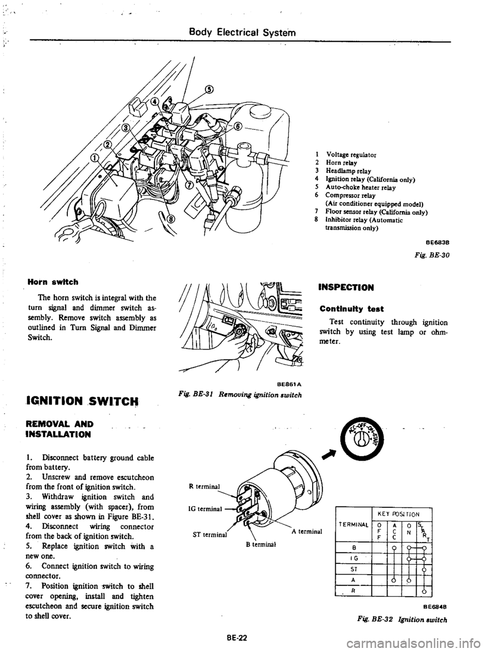
Body
Electrical
System
Horn
switch
The
horn
switch
is
integral
with
the
turn
signal
and
dimmer
switch
as
sembly
Remove
switch
assembly
as
outlined
in
Turn
Signal
and
Dimmer
Switch
IGNITION
SWITCH
BE861A
Fig
BE
3
I
Removing
ignition
switch
REMOVAL
AND
INSTALLATION
I
Disconnect
battery
ground
cable
from
battery
2
Unscrew
and
remove
escutcheon
from
the
front
of
ignition
switch
3
Withdraw
ignition
switch
and
wiring
assembly
with
spacer
from
shell
cover
as
shown
in
Figure
BE
3
4
Disconnect
wiring
connector
from
the
back
of
ignition
switch
5
Replace
ignition
switch
with
a
new
one
6
Connect
ignition
switch
to
wiring
connector
7
Position
ignition
switch
to
shell
cover
opening
install
and
tighten
escutcheon
and
secure
ignition
switch
to
shell
cover
R
terminal
1G
terminal
ST
terminal
B
terminal
8E
22
1
Voltage
regulator
2
Horn
relay
3
Headlamp
relay
4
Ignition
relay
California
only
5
Auto
choke
heater
relay
6
Compressor
relay
Au
conditioner
equipped
model
7
Floor
sensor
relay
California
only
8
Inhibitor
relay
Automatic
tran5mission
only
INSPECTION
BE683B
Fig
BE
30
ContInuity
test
Test
continuity
through
ignition
switch
by
using
test
lamp
or
ohm
meter
C
A
terminal
TERMINAL
0
F
F
B
IG
ST
A
R
KEY
FOSITlON
t
1
o
j
u
u
I
I
A
C
C
Fig
BE
32
Ignition
witch
BE6848
Page 468 of 537
Body
Electrical
System
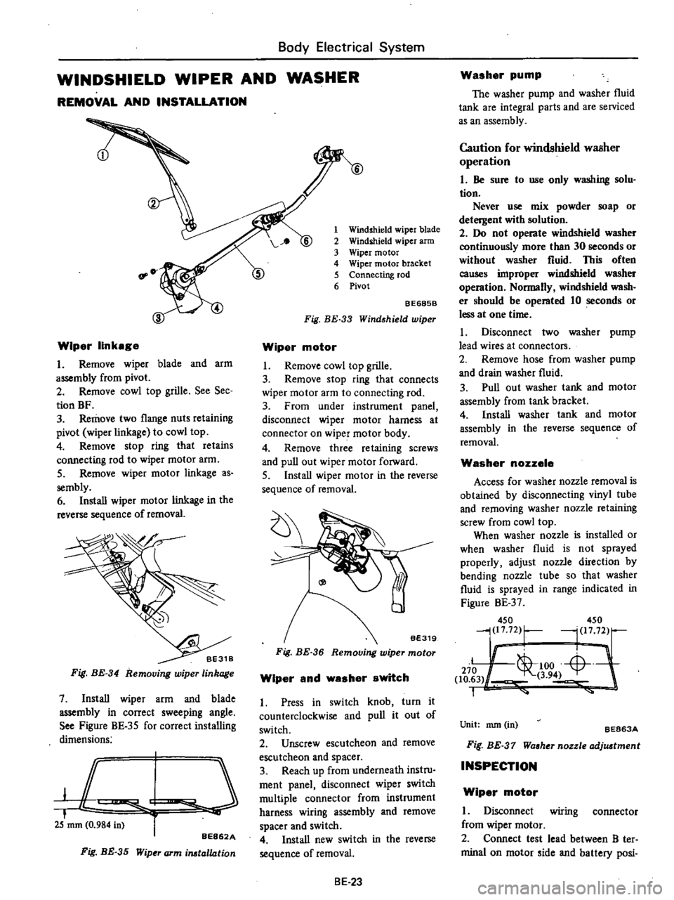
WINDSHIELD
WIPER
AND
WASHER
REMOVAL
AND
INSTALLATION
Wiper
linkage
I
Remove
wiper
blade
and
arm
assembly
from
pivot
2
Remove
cowl
top
grille
See
Sec
tion
BF
3
Remove
two
flange
nuts
retaining
pivot
wiper
linka
e
to
cowl
top
4
Remove
stop
ring
that
retains
connecting
rod
to
wiper
motor
arm
5
Remove
wiper
motor
linkage
as
sembly
6
Install
wiper
motor
linkage
in
the
reverse
sequence
of
removal
Fig
BE
34
Removing
wiper
linkage
7
Install
wiper
arm
and
blade
assembly
in
correct
sweeping
angle
See
Figure
BE
35
for
correct
installing
dimensions
JC
I
i
25
mm
0
984
in
r
BE862A
Fig
BE
35
Wip
J
arm
irutallation
1
Windshield
wiper
blade
2
Windihield
wiper
arm
3
Wiper
motor
4
Wiper
motor
bracket
5
Connecting
rod
6
Pivot
BE685B
Fig
BE
33
Wind
hield
wiper
Wiper
motor
I
Remove
cowl
top
grille
3
Remove
stop
ring
that
connects
wiper
motor
arm
to
connecting
rod
3
From
under
instrument
panel
disconnect
wiper
motor
harness
at
connector
on
wiper
motor
body
4
Remove
three
retaining
screws
and
pull
out
wiper
motor
forward
5
Install
wiper
motor
in
the
reverse
sequence
of
removal
Fig
BE
36
Wiper
and
washer
switch
1
Press
in
switch
knob
turn
it
counterclockwise
and
pull
it
out
of
switch
2
Unscrew
escutcheon
and
remove
escutcheon
and
spacer
3
Reach
up
from
underneath
instru
ment
panel
disconnect
wiper
switch
multiple
connector
from
instrument
harness
wiring
assembly
and
remove
spacer
and
switch
4
Install
new
switch
in
the
reverse
sequence
of
removal
BE
23
Washer
pump
The
washer
pump
and
washer
fluid
tank
are
integral
parts
and
are
serviced
as
an
assembly
Caution
for
windshield
waBher
operation
I
Be
sure
to
use
only
washing
solu
tion
Never
use
mix
powder
soap
or
detergent
with
solution
2
Do
not
operate
windshield
washer
continuously
more
than
30
seconds
or
without
washer
fluid
This
often
causes
improper
windshield
washer
operation
Normally
windshield
wash
er
should
be
operated
10
seconds
or
less
at
one
time
I
Disconnect
two
washer
pump
lead
wires
at
connectors
2
Remove
hose
from
washer
pump
and
drain
washer
fluid
3
Pull
out
washer
tank
and
motor
assembly
from
tank
bracket
4
Install
washer
tank
and
motor
assembly
in
the
reverse
sequence
of
removal
Washer
nozzele
Access
for
washer
nozzle
removal
is
obtained
by
disconnecting
vinyl
tube
and
removing
washer
nozzle
retaining
screw
from
cowl
top
When
washer
nozzle
is
installed
or
when
washer
fluid
is
not
sprayed
properly
adjust
nozzle
direction
by
bending
nozzle
tube
so
that
washer
fluid
is
sprayed
in
range
indicated
in
Figure
BE
37
450
450
j217
72
r
l
1772
Ii
L
1
00
Li
L
J
270
1
to
63
3
94
1
Unit
nun
in
BE863A
Fif
BE
37
Waaher
nozzle
adjuatment
INSPECTION
Wiper
motor
I
Disconnect
wiring
connector
from
wiper
motor
2
Connect
test
lead
between
B
ter
minal
on
motor
ide
and
battery
posi
Page 469 of 537
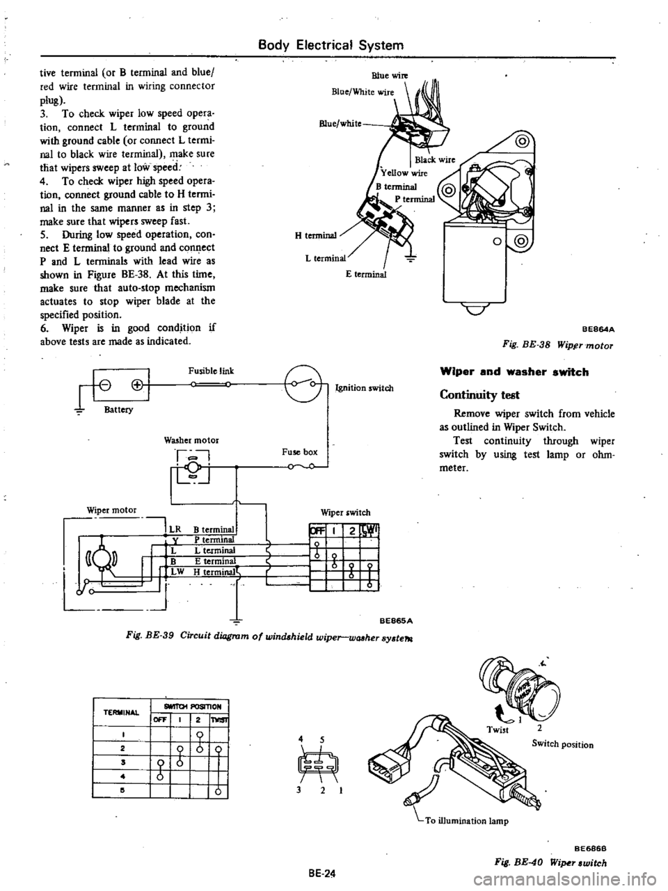
Body
Electrical
System
tive
terminal
or
B
terminal
and
blue
red
wire
terminal
in
wiring
connector
plug
3
To
check
wiper
low
speed
opera
tion
connect
L
terminal
to
ground
with
ground
cable
or
connect
L
termi
nal
to
black
wire
terminal
make
sure
that
wipers
sweep
at
low
speed
4
To
check
wiper
high
speed
opera
tion
connect
ground
cable
to
H
termi
nal
in
the
same
manner
as
in
step
3
make
sure
that
wipers
sweep
fast
5
During
low
speed
operation
con
nect
E
terminal
to
ground
and
conl
ect
P
and
L
terminals
with
lead
wire
as
shown
in
Figure
BE
38
At
this
time
make
sure
that
auto
stop
mechanism
actuates
to
stop
wiper
blade
at
the
specified
position
6
Wiper
is
in
good
condition
if
above
tests
are
made
as
indicated
H
tenninal
Blue
white
o
@
C
BE864A
Fig
BE
38
Wipftrmotor
rt
Cl
Battery
Fusible
link
e
Ignition
witch
Wiper
and
washer
switch
I
D
j
Fuse
box
Y
O
Continuity
test
Remove
wiper
switch
from
vehicle
as
outlined
in
Wiper
Switch
Test
continuity
through
wiper
switch
by
using
test
lamp
or
ohm
meter
WQ5hcr
motor
Wiper
motor
191
LR
y
I
L
I
w
J
Wiper
switch
B
terminal
P
tenninal
L
terminal
E
terminal
H
t
rmjrW
r
21
1
b
I
r
1
I
I
BE865A
Fig
BE
39
Circuit
diagram
of
windshield
wiper
wtUher
sy
te7tl
TERMINAL
I
SlOIT01
POSIl10N
I
I
OFF
2
1
1
2
I
b
ii
4
5
Switch
position
2
I
Z
m
Z
I
I
I
I
I
I
I
10
I
3
2
BE686B
Fig
BE
40
Wi
r
witch
8E
24
Page 470 of 537
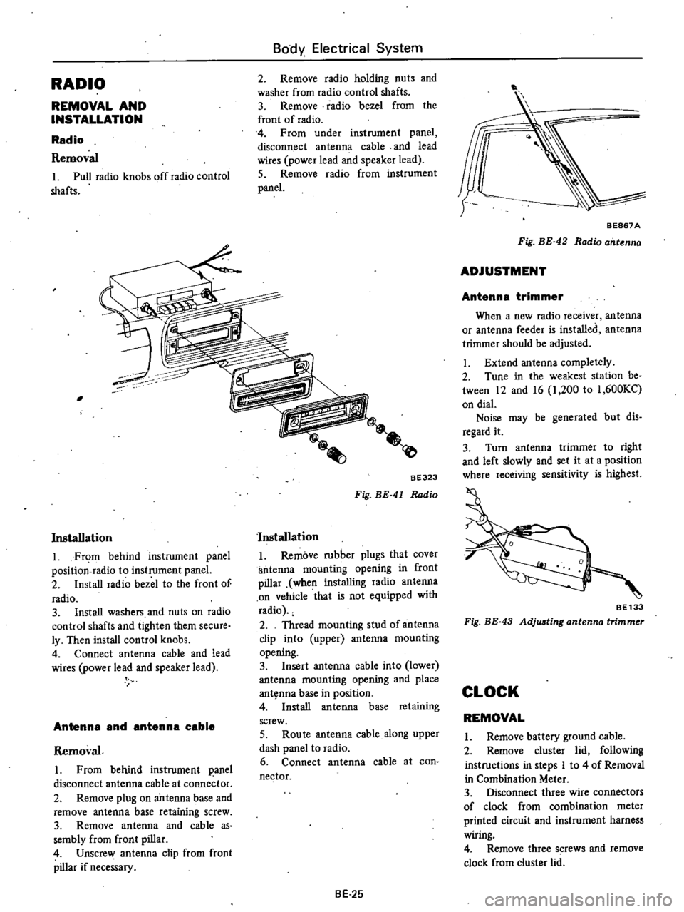
RADIO
REMOVAL
AND
INSTALLATION
Radio
Removal
Pull
radio
knobs
offradio
control
shafts
Body
Electrical
System
2
Remove
radio
holding
nuts
and
washer
from
radio
control
shafts
3
Remove
radio
bezel
from
the
front
of
radio
4
From
under
instrument
panel
disconnect
antenna
cable
and
lead
wires
power
lead
and
speaker
lead
5
Remove
radio
from
instrument
panel
Installation
Fr
m
behind
instrument
panel
position
radio
to
instrument
panel
2
Install
radio
bezel
to
the
front
of
radio
3
Install
washers
and
nuts
on
radio
control
shafts
and
tighten
them
secure
ly
Then
install
control
knobs
4
Connect
antenna
cable
and
lead
wires
power
lead
and
speaker
lead
Antenna
and
antenna
cable
Removal
From
behind
instrument
panel
disconnect
antenna
cable
at
conne
tor
2
Remove
plug
on
antenna
base
and
remove
antenna
base
retaining
screw
3
Remove
antenna
and
cable
as
sembly
from
fr
ont
pillar
4
Unscrew
antenna
clip
from
front
pillar
if
necessary
aE323
Fig
BE
41
Radio
Installation
Remove
rubber
plugs
that
cover
antenna
mounting
opening
in
front
pillar
when
installing
radio
antenna
on
vehicle
that
is
not
equipped
with
radio
2
Thread
mounting
stud
of
antenna
clip
into
upper
antenna
mountins
opening
3
Insert
antenna
cable
into
lower
antenna
mounting
opening
and
place
ant
nna
base
in
position
4
Install
antenna
base
retaining
screw
5
Route
antenna
cable
along
upper
dash
panel
to
radio
6
Connect
antenna
cable
at
con
nector
BE
25
t
BEB67
A
Fig
BE
42
Radio
ant
nna
ADJUSTMENT
Antenna
trimmer
When
a
new
radio
receiver
antenna
or
antenna
feeder
is
installed
antenna
trimmer
should
be
adjusted
Extend
antenna
completely
2
Tune
in
the
weakest
station
be
tween
12
and
16
1
200
to
1
600KC
on
dial
Noise
may
be
generated
but
dis
regard
it
3
Turn
antenna
trimmer
to
right
and
left
slowly
and
set
it
at
a
position
where
receiving
sensitivity
is
highest
SE133
Fig
BE
43
Adjwting
antenna
trimmer
CLOCK
REMOVAL
Remove
battery
ground
cable
2
Remove
cluster
lid
following
instructions
in
steps
I
to
4
of
Removal
in
Combination
Meter
3
Disconnect
three
wire
connectors
of
clock
from
combination
meter
printed
circuit
and
instrument
harnes
wiring
4
Remove
three
s
rews
and
remove
clock
from
cluster
lid
Page 471 of 537

INSTALLATION
I
Position
clock
to
cluster
lid
and
install
three
screws
2
Connect
three
wire
connectors
of
clock
to
each
connection
two
to
combination
meter
printed
circuit
one
to
instrument
h
ness
wiring
3
Install
cluster
lid
to
instrument
panel
4
Connect
battery
ground
cable
HEATER
DESCRIPTION
@
Body
Electrical
System
Fig
BE
44
Clock
1
Defroster
nozzle
L
U
2
Deflor
tcr
duct
L
R
3
Heater
control
4
Resistor
5
Heater
motor
6
Heater
case
7
Ventilator
knob
8
Heater
core
9
Conuol
cable
clip
10
Heater
cock
11
Defroster
duct
R
H
12
Defroster
nozzle
R
H
BE687B
Fig
BE
45
Heater
comtruction
BE
26
Page 472 of 537
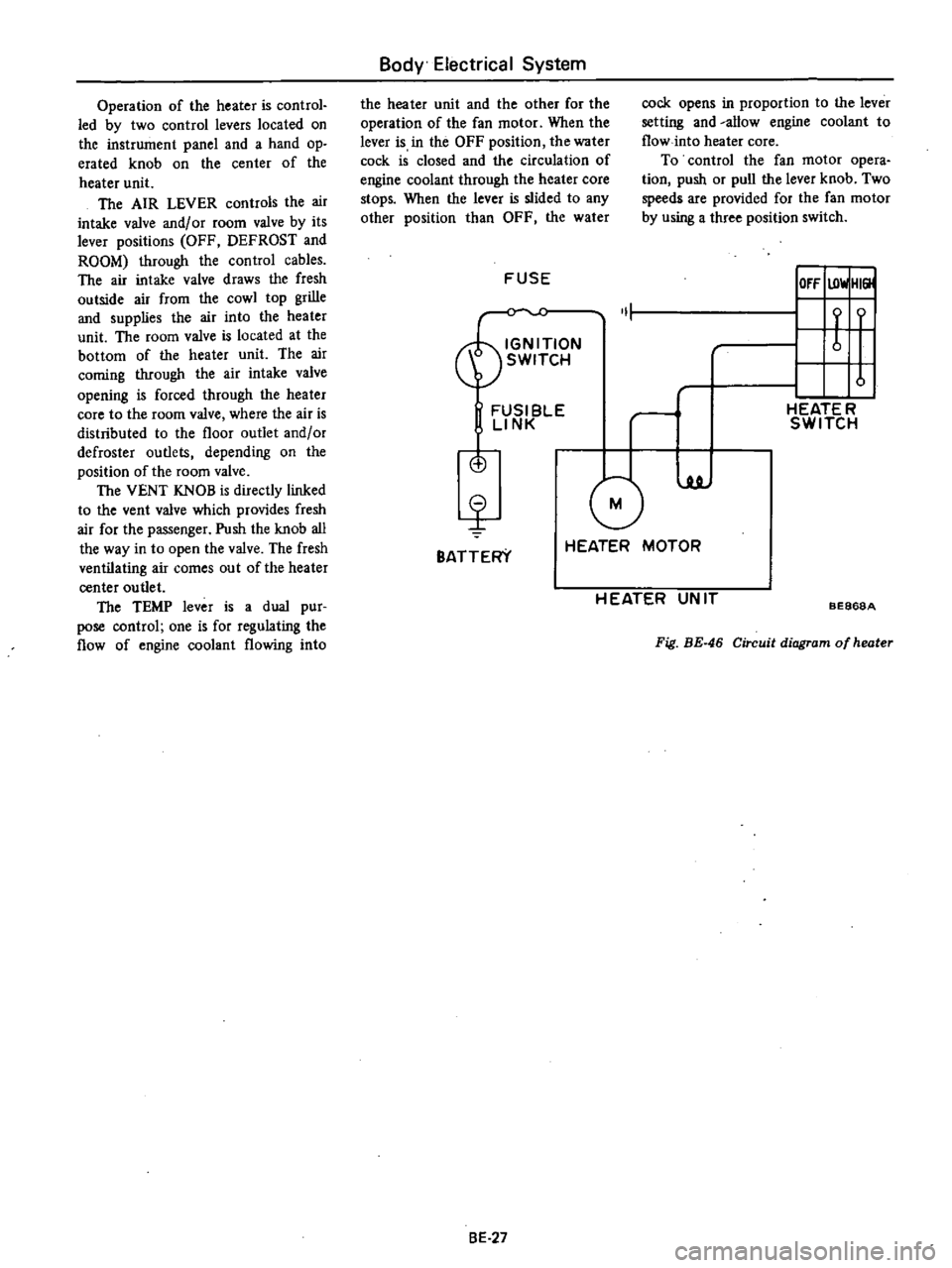
Operation
of
the
heater
is
control
led
by
two
control
levers
located
on
the
instrument
panel
and
a
hand
op
erated
knob
on
the
center
of
the
heater
unit
The
AIR
LEVER
controls
the
air
intake
valve
and
or
room
valve
by
its
lever
positions
OFF
DEFROST
and
ROOM
through
the
control
cables
The
air
intake
valve
draws
the
fresh
outside
air
from
the
cowl
top
grille
and
supplies
the
air
into
the
heater
unit
The
room
valve
is
located
at
the
bottom
of
the
heater
unit
The
air
coming
through
the
air
intake
valve
opening
is
forced
through
the
heater
core
to
the
room
valve
where
the
air
is
distributed
to
the
floor
outlet
and
or
defroster
outlets
depending
on
the
position
of
the
room
valve
The
VENT
KNOB
is
directly
linked
to
the
vent
valve
which
provides
fresh
air
for
the
passenger
Push
the
knob
all
the
way
in
to
open
the
valve
The
fresh
ventilating
air
comes
out
of
the
heater
center
outlet
The
TEMP
lever
is
a
dual
pur
pose
control
one
is
for
regulating
the
flow
of
engine
coolant
flowing
into
Body
Electrical
System
the
heater
unit
and
the
other
for
the
operation
of
the
fan
motor
When
the
lever
is
in
the
OFF
position
the
water
cock
is
closed
and
the
circulation
of
engine
coolant
through
the
heater
core
stops
When
the
lever
is
slided
to
any
other
position
than
OFF
the
water
cock
opens
in
proportion
to
the
lever
setting
and
allow
engine
coolant
to
flow
into
heater
core
To
control
the
fan
motor
opera
tion
push
or
pull
the
lever
knob
Two
speeds
are
provided
for
the
fan
motor
by
using
a
three
position
switch
FUSE
IOfF
UlwlHI
ON
1
t
f
SWITCH
u
FUSI
BlE
rl
HEATE
R
LINK
SWITCH
is
G
luJ
BATTERY
HEATER
MOTOR
H
EATER
UN
IT
BE868A
Fig
BE
46
Circuit
diagram
of
heater
8E
27