check oil DATSUN PICK-UP 1977 Repair Manual
[x] Cancel search | Manufacturer: DATSUN, Model Year: 1977, Model line: PICK-UP, Model: DATSUN PICK-UP 1977Pages: 537, PDF Size: 35.48 MB
Page 229 of 537
Inspection
Note
To
clean
or
wash
all
parts
of
master
cylinder
operating
cylinder
and
piping
clean
brake
fluid
must
be
used
Never
use
minera10ils
llUch
as
gasoline
and
kerosene
It
will
ruin
the
rubber
parts
of
the
hydrau
lic
system
I
Check
cylinder
and
piston
for
uneven
wear
or
damage
and
if
neces
sary
replace
2
If
the
clearance
between
cylinder
and
piston
is
more
than
0
15
mm
0
0059
in
replace
cylinder
3
Renew
piston
cup
when
dis
assembled
It
must
also
be
replaced
when
wear
or
deformation
due
to
fatigue
or
damage
is
found
4
Damaged
dust
cover
oil
reservoir
or
cap
should
be
replaced
Return
spring
and
valve
spring
must
also
be
replaced
when
they
are
broken
or
weak
5
Replace
clutch
hose
and
tube
if
any
abnormal
sign
of
damage
or
de
fro
ti
n
is
found
OPERATING
CYLINDER
Removal
and
installation
Removal
1
Detach
clutch
hose
from
operat
ing
cylinder
2
Remove
two
bolts
securing
op
erating
cylinder
to
clutch
housing
Installation
Install
in
the
reverse
order
of
re
moval
Observe
the
following
instructions
Bleed
air
thoroughly
from
clutch
hydraulic
system
2
Do
not
install
return
spring
or
clutch
will
not
be
disengaged
properly
Tightening
torque
Operating
cylinder
securing
bolt
2
5
to
3
5
kg
m
18
to
25
ft
lb
Bleeder
screw
0
7
to
0
9
kg
m
5
1
to
6
5
ft
Ib
Clutch
hose
connector
1
7
to
2
0
kg
m
12
to
14
ft
b
CLUTCH
Disassembly
and
assembly
Disassembly
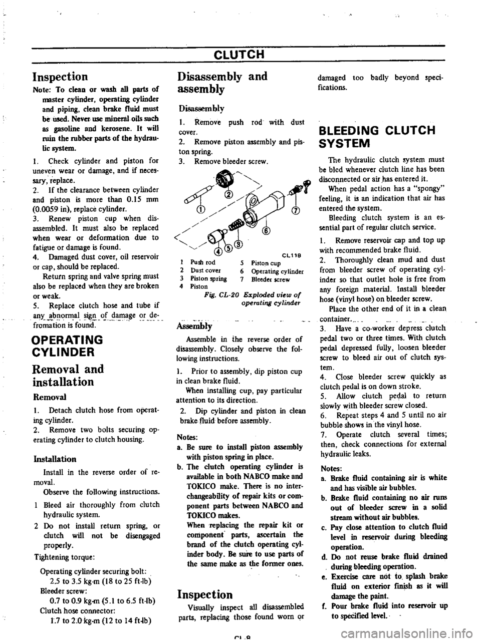
1
Remove
push
rod
with
dust
cover
2
Remove
piston
assembly
and
pis
ton
spring
3
Remove
bleeder
screw
1
6
Cl11B
5
Piston
cup
6
Operating
cylinder
7
Bleeder
screw
1
Push
rod
2
Dust
cover
3
Piston
spring
4
Piston
Fig
CL
20
Exploded
view
of
operating
cyUnder
Assembly
Assemble
in
the
reverse
order
of
disassembly
Closely
observe
the
fol
lowing
instructions
1
Prior
to
assembly
dip
piston
cup
in
clean
brake
fluid
When
installing
cup
pay
particular
attention
to
its
direction
2
Dip
cylinder
and
piston
in
clean
brake
fluid
before
assembly
Notes
a
Be
sure
to
install
piston
assembly
with
piston
spring
in
place
b
The
clutch
operating
cylinder
is
available
in
both
NABCO
make
and
TOKICO
make
There
is
no
inter
changeability
of
repair
kits
or
com
ponent
parts
between
NABCO
and
TOKICO
makes
When
replacing
the
repair
kit
or
component
parts
ascertain
the
brand
of
the
clutch
operating
cyl
inder
bndy
Be
sure
to
use
parts
of
the
same
make
as
the
former
ones
Inspection
Visually
inspect
all
disassembled
parts
replacing
those
found
worn
or
rl
Q
damaged
too
badly
beyond
speci
fications
BLEEDING
CLUTCH
SYSTEM
The
hydraulic
clutch
system
must
be
bled
whenever
clutch
line
has
been
disconnected
or
air
has
entered
it
When
pedal
action
has
a
spongy
feeling
it
is
an
indication
that
air
has
entered
the
system
Bleeding
clutch
system
is
an
es
sential
part
of
regular
clutch
service
I
Remove
reservoir
cap
and
top
up
with
recommended
brake
fluid
2
Thoroughly
clean
mud
and
dust
from
bleeder
screw
of
operating
cyl
inder
so
that
outlet
hole
is
free
from
any
foreign
rnaterial
Install
bleeder
hose
vinyl
hose
on
bleeder
screw
Place
the
other
end
of
it
in
a
clean
container
3
Have
a
co
worker
depress
clutch
pedal
two
or
three
times
With
clu
tch
pedal
depressed
fully
loosen
bleeder
screw
to
bleed
air
out
of
clutch
sys
tern
4
Close
bleeder
screw
quickly
as
clutch
pedal
is
on
down
stroke
5
Allow
clutch
pedal
to
return
slowly
with
bleeder
screw
closed
6
Repeat
steps
4
and
5
until
no
air
bubble
shows
in
the
vinyl
hose
7
Operate
clutch
several
times
then
check
connections
for
external
hydraulic
leaks
Notes
a
Brake
fluid
containing
air
is
white
and
has
visible
air
bubbles
b
Brake
fluid
containing
no
air
runs
out
of
bleeder
screw
in
a
solid
stream
without
air
bubble
c
Pay
close
attention
to
clutch
fluid
level
in
reservoir
during
bleeding
operation
d
Do
not
reuse
brake
fluid
drained
during
bleeding
operation
e
Exercise
care
not
to
splash
brake
fluid
on
exterior
fInish
as
it
will
damage
the
paint
f
Pour
brake
fluid
into
reservoir
up
to
specifIed
level
Page 231 of 537
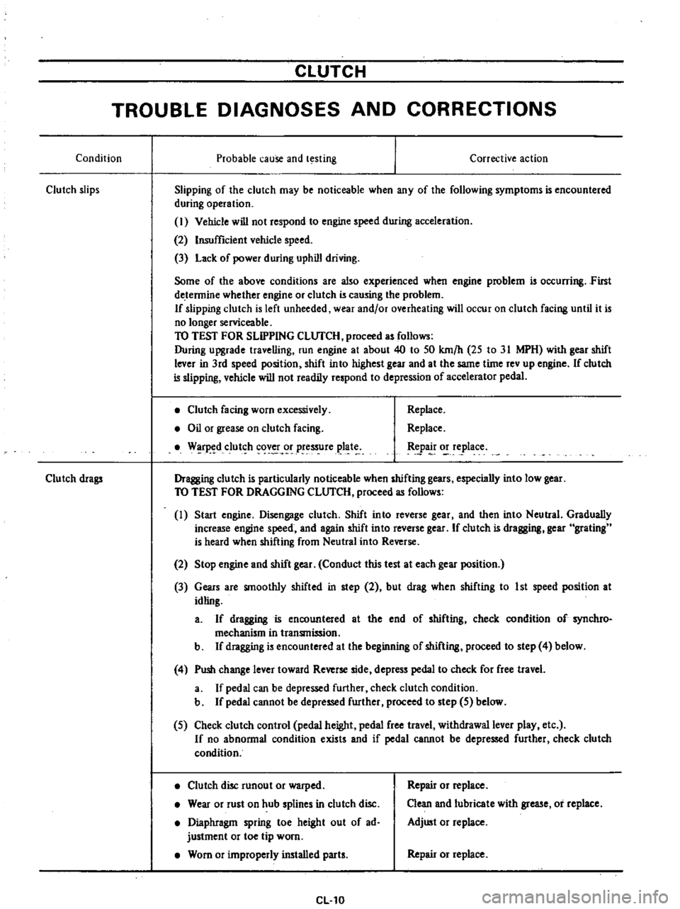
CLUTCH
TROUBLE
DIAGNOSES
AND
CORRECTIONS
Condition
Probable
cause
and
testing
Clutch
slips
Corrective
action
Slipping
of
the
clutch
may
be
noticeable
when
any
of
the
following
symptoms
is
encountered
during
operation
I
Vehicle
will
not
respond
to
engine
speed
during
acceleration
2
Insufficient
vehicle
speed
3
Lack
of
power
during
uphill
driving
Some
of
the
above
conditions
are
also
experienced
when
engine
problem
is
oc
urring
First
de
tennine
whether
engine
or
clutch
is
causing
the
problem
If
slipping
clutch
is
left
unheeded
wear
and
or
overheating
will
occur
on
clutch
facing
until
it
is
no
longer
serviceable
TO
TEST
FOR
SLIPPING
CLlJfCH
proceed
as
follows
During
upgrade
travelling
run
engine
at
about
40
to
50
km
h
25
to
31
MPH
with
gear
shift
lever
in
3rd
speed
position
shift
into
highest
gear
and
at
the
same
time
rev
up
engine
If
clutch
is
slipping
vehicle
will
not
readily
respond
to
depression
of
accelerator
pedal
Clutch
facing
worn
excessively
Oil
or
grease
on
clutch
facing
W
r
d
clut
h
cov
r
pressure
plat
Replace
Replace
tpa
o
e
lace
Dragging
clutch
is
particularly
noticeable
when
shifting
gears
especially
into
low
gear
TO
TEST
FOR
DRAGGING
CLlJfCH
proceed
as
follows
I
Start
engine
Disengage
clutch
Shift
into
reverse
gear
and
then
into
Neutral
Gradually
increase
engine
speed
and
again
shift
into
reverse
gear
If
clutch
is
dragging
gear
grating
is
heard
when
shifting
from
Neutral
into
Reverse
Clutch
drags
2
Stop
engine
and
shift
gear
Conduct
this
test
at
each
gear
position
3
Gears
are
smoothly
shifted
in
step
2
but
drag
when
shifting
to
1st
speed
position
at
idling
a
If
dragging
is
encountered
at
the
end
of
shifting
check
condition
of
synchro
mechanism
in
transmission
b
If
dragging
is
encountered
at
the
beginning
of
shifting
proceed
to
step
4
below
4
Push
change
lever
toward
Reverse
side
depress
pedal
to
check
for
free
travel
a
If
pedal
can
be
depressed
further
check
clutch
condition
b
If
pedal
cannot
be
depressed
further
proceed
to
step
5
below
5
Check
clutch
control
pedal
height
pedal
free
travel
withdrawal
lever
play
etc
If
no
abnonnal
condition
exists
and
if
pedal
cannot
be
depressed
further
check
clutch
condition
Clutch
disc
runout
or
warped
Wear
or
rust
on
hub
splines
in
clutch
disc
Diaphragm
spring
toe
height
out
of
ad
justment
or
toe
tip
worn
Worn
or
improperly
installed
parts
CL10
Repair
or
replace
Clean
and
lubricate
with
grease
or
replace
Adjust
or
replace
Repair
or
replace
Page 237 of 537
Manual
Transmission
o
cCl
4
@
@
fl
t
o
@
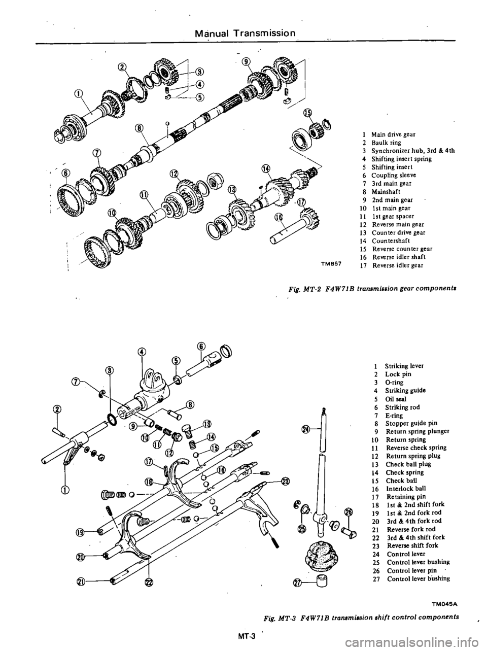
Fig
MT
3
MT
3
TM857
1
Main
drive
gear
2
Baulk
ring
3
d
4th
3
Synchronizer
hub
r
4
Shifting
insert
spnng
5
Shifting
insert
6
Coupling
sleeve
7
3rd
main
gear
8
Mainshaft
9
2nd
main
gear
10
1st
main
gear
11
ht
gear
spacer
12
Reverse
main
gear
13
Counter
drive
gear
14
Countershaft
15
Reverse
counter
gear
16
Reverse
idler
shaft
17
Reverse
idler
gear
Fig
MT
2
n
ear
component
F4W71B
transmlsBIO
g
@
f1f@
n
1
2
3
4
5
6
7
8
9
10
11
12
13
14
15
16
17
18
19
20
21
22
23
24
25
26
27
Striking
lever
Lock
pin
O
ring
Striking
guide
Oil
sea1
Striking
rod
E
ring
Stopper
guide
pm
Return
spring
plunger
Return
spring
Reverse
check
spnng
Return
spring
plug
Check
ball
plug
Check
spring
Check
baD
Interlock
ball
Retaining
pin
k
1st
2nd
shift
or
ht
2nd
fork
rod
3rd
4th
fork
rod
Reverse
fork
rod
3rd
4th
shift
fork
Reverse
shift
fork
Con
trollever
Control
lever
b
shmg
Control
lever
p
n
Control
lever
bushmg
TM045A
I
ponents
shift
contro
com
F4W71
B
transmuswn
Page 242 of 537
REAR
EXTENSION
DISASSEMBLY
Remove
lock
pin
from
striking
lever
and
remove
striking
rod
Manual
Transmission
Note
00
not
diSlssemble
rear
exten
sion
bush
from
rear
extension
ADAPTER
PLATE
DISASSEMBLY
I
Remove
six
6
bearing
retainer
attaching
screws
with
an
impact
wrench
and
remove
bearing
retainer
from
adapter
plate
2
Remove
reverse
idler
shaft
3
Remove
mainshaft
bearing
from
the
rear
extension
side
INSPECTION
Wash
all
parts
in
a
suitable
cleaning
solvent
and
check
for
wear
damage
or
other
faulty
conditions
Notes
a
Be
careful
not
to
damage
any
parts
with
scraper
b
00
not
clean
wash
or
soak
oil
seals
in
solvent
TRANSMISSION
CASE
AND
REAR
EXTENSION
HOUSING
I
Clean
with
solvent
thoroughly
and
check
for
cracks
which
might
cause
oil
leak
or
other
faulty
con
ditions
2
Check
mating
surface
of
the
case
to
engine
or
adapter
plate
for
small
nicks
projection
or
sealant
e
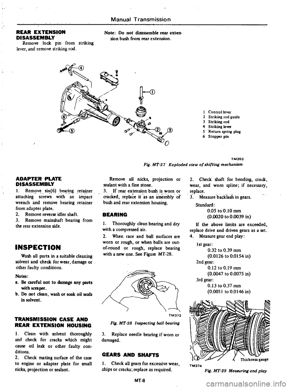
1
Control
lever
2
Striking
rod
guide
3
Striking
rod
4
Striking
lever
5
Return
spring
plug
6
Stopper
pin
TM353
Fig
MT
27
Exploded
view
of
shifting
mechani6m
Remove
all
nicks
projection
or
sealant
with
a
frne
stone
3
If
rear
extension
bush
is
worn
or
cracked
replace
it
as
an
assembly
of
bush
and
rear
extension
housing
BEARING
I
Thoroughly
clean
bearing
and
dry
with
a
compressed
air
2
When
race
and
ball
surfaces
are
worn
or
rough
or
when
balls
are
out
of
round
or
rough
replacebearihg
with
a
new
one
See
Figure
MT
28
I
TM372
Fig
MT
28
l
pecting
ball
bearing
3
Replace
needle
bearing
if
worn
or
damaged
GEARS
AND
SHAFTS
I
Check
all
gears
for
excessive
wear
chips
or
cracks
replace
as
required
MT
8
2
Check
shaft
for
bending
crack
wear
and
worn
spline
if
necessary
replace
3
Measure
backiasii
in
gears
Standard
0
05
to0
10mm
0
0020
to
0
0039
in
If
the
above
limits
are
exceeded
replace
drive
and
driven
gears
as
a
set
4
Measure
gear
end
play
1st
gear
0
32
to
0
39
mm
0
0126
to
0
0154
in
2nd
gear
0
12
to
0
19
mm
0
0047
to
0
0075
in
3rd
gear
0
13
to
0
37
mm
0
0051
to
0
0146
in
TM374
Fig
MT
29
Measuring
end
play
Page 243 of 537
5
Check
for
stripped
or
damaged
speedometer
pinion
gear
If
necessary
replace
BAULK
RI
NG
I
Replace
baulk
ring
if
found
to
be
deformed
cracked
or
otherwise
dam
aged
excessively
2
Place
baulk
ring
in
position
on
gear
cone
While
holding
baulk
ring
against
gear
as
far
as
it
will
go
measure
gap
between
baulk
ring
and
outer
gear
If
gap
is
small
discard
baulk
ring
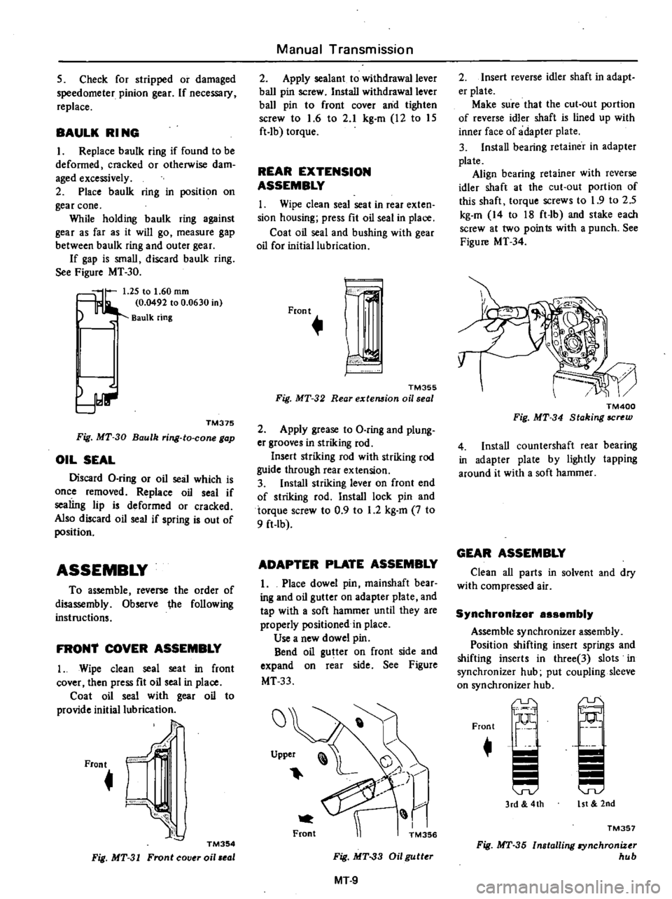
See
Figure
MT
30
5
lr
1
25
to
1
60
rom
0
0492
to
0
0630
in
Baulk
ring
TM375
Fig
MT
30
Baulk
ring
to
cone
gap
OIL
SEAL
Discard
O
ring
or
oil
seal
which
is
once
removed
Replace
oil
seal
if
sealing
lip
is
deformed
or
cracked
Also
discard
oil
seal
if
spring
is
out
of
position
ASSEMBLY
To
assemble
reverse
the
order
of
disassembly
Observe
ihe
following
instructions
FRON1
COVER
ASSEMBLY
I
Wipe
clean
seal
seat
in
front
cover
then
press
fit
oil
seal
in
place
Coat
oil
seal
with
gear
oil
to
provide
initial
lubrication
Front
J
f
C
J
TM354
Fig
MT
31
Front
cov
oil
eol
Manual
Transmission
2
Apply
sealant
to
withdrawal
lever
ball
pin
screw
Install
withdrawal
lever
ball
pin
to
front
cover
and
tighten
screw
to
1
6
to
2
1
kg
m
12
to
15
ft
lb
torque
REAR
EXTENSION
ASSEMBLY
1
Wipe
clean
seal
seat
in
rear
exten
sion
housing
press
fit
oil
seal
in
place
Coat
oil
seal
and
bushing
with
gear
oil
for
initial
lubrication
Front
h
TM355
Fig
MT
32
Rear
extemion
oil
seal
2
Apply
grease
to
O
ring
and
plung
er
grooves
in
striking
rod
Insert
striking
rod
with
striking
rod
guide
through
rear
extension
3
Install
striking
lever
on
front
end
of
striking
rod
Install
lock
pin
and
torque
screw
to
0
9
to
1
2
kg
m
7
to
9
ft
Ib
ADAPTER
PLATE
ASSEMBLY
1
Place
dowel
pin
mainshaft
bear
ing
and
oil
gutter
on
adapter
plate
and
tap
with
a
soft
hammer
until
they
are
properly
positioned
in
place
Use
a
new
dowel
pin
Bend
oil
gutter
on
front
side
and
expand
on
rear
side
See
Figure
MT33
J
7
r
M356
Upper
Front
Fig
MT
33
Oil
gutter
MT
9
2
Insert
reverse
idler
shaft
in
adapt
er
plate
Make
sure
that
the
cut
out
portion
of
reverse
idler
shaft
is
lined
up
with
inner
face
of
adapter
plate
3
Install
bearing
retainer
in
adapter
plate
Align
bearing
retainer
with
reverse
idler
shaft
at
the
cut
out
portion
of
this
shaft
torque
screws
to
1
9
to
2
5
kg
m
14
to
18
ft
lb
and
stake
each
screw
at
two
poin
Is
with
a
punch
See
Figure
MT
34
TM400
Fig
MT
34
Staking
SCN
W
4
Install
countershaft
rear
bearing
in
adapter
plate
by
lightly
tapping
around
it
with
a
soft
hammer
GEAR
ASSEMBLY
Clean
all
parts
in
solvent
and
dry
with
compressed
air
Synchronizer
888embly
Assemble
synchronizer
assembly
Position
shifting
insert
springs
and
shifting
inserts
in
three
3
slots
in
synchronizer
hub
put
coupling
sleeve
on
synchronizer
hub
r
Front
3rd
4th
15t
2nd
TM351
Fig
MT
35
Installing
synchronizer
hub
Page 247 of 537
Note
Prior
to
assembling
reverse
fork
rod
instaU
two
2
interlock
balls
into
adapter
piate
as
shown
in
Figure
MT
I6
6
Install
check
ball
and
check
ball
spring
Apply
sealant
to
check
ball
plug
and
install
it
in
place
Align
notch
in
reverse
fork
rod
with
check
ball
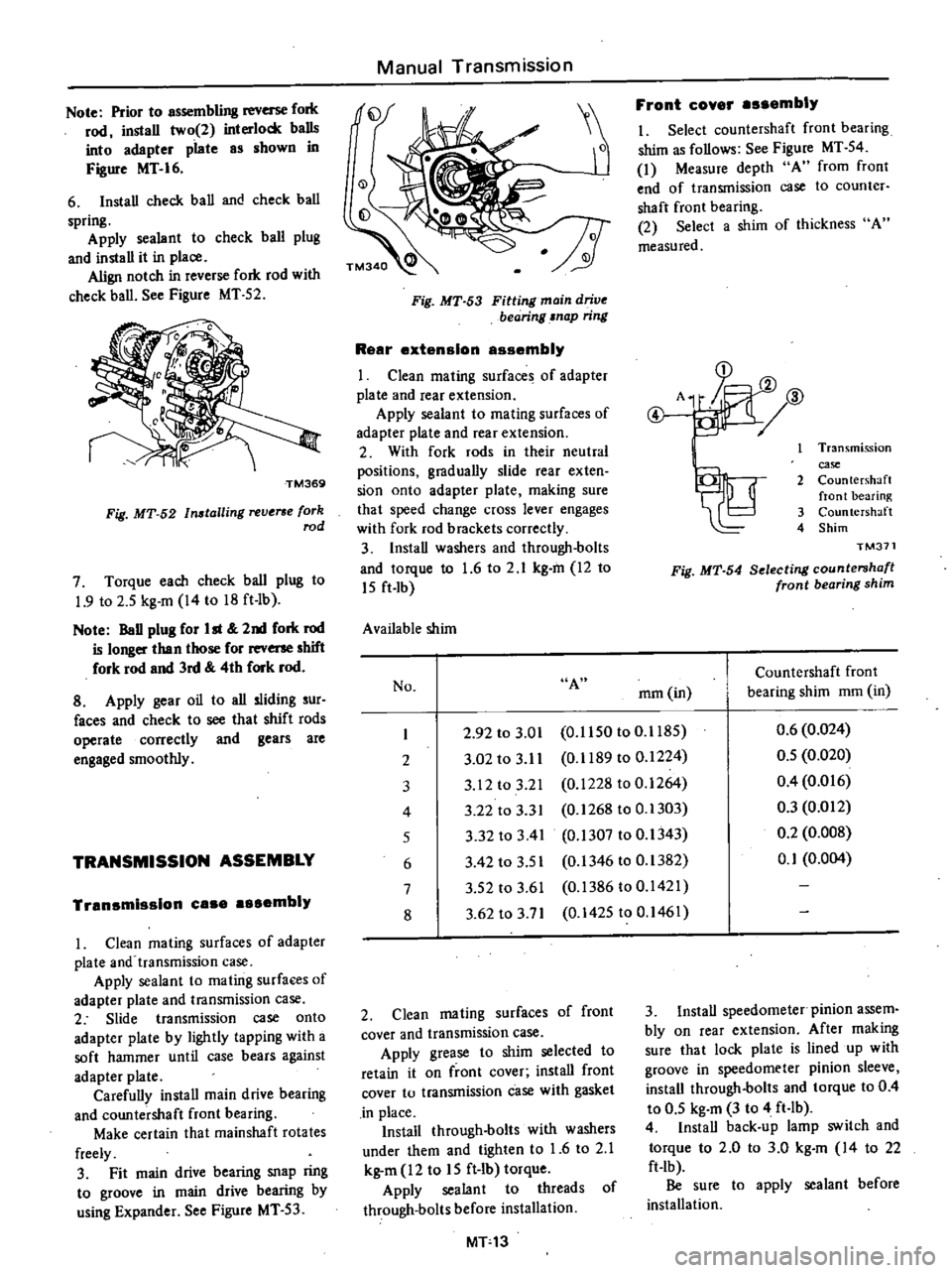
See
Figure
MT
52
TM369
Fig
MT
52
Installing
reverse
fork
rod
7
Torque
each
check
ball
plug
to
1
9
to
2
5
kg
m
14
to
18
ft
Ib
Note
BaD
plug
for
ht
2nd
fork
rod
is
longer
than
those
for
rev
shift
fork
rod
and
3rd
4th
fork
rod
8
Apply
gear
oil
to
all
sliding
sur
faces
and
check
to
see
that
shift
rods
operate
correctly
and
gears
are
engaged
smoothly
TRANSMISSION
ASSEMBLY
Tran
mis
lon
ea
mbly
1
Clean
mating
surfaces
of
adapter
plate
and
transmission
case
Apply
sealant
to
mating
surfaces
of
adapter
plate
and
transmission
case
2
Slide
transmission
case
onto
adapter
plate
by
lightly
tapping
with
a
soft
hammer
until
case
bears
against
adapter
plate
Carefully
install
main
drive
bearing
and
countershaft
front
bearing
Make
certain
that
mainshaft
rotates
freely
3
Fit
main
drive
bearing
snap
ring
to
groove
in
main
drive
bearing
by
using
Expander
See
Figure
MT
53
Manual
Transmission
Fig
MT
53
Fitting
main
drive
bearing
snap
ring
R
ar
xt
nslon
ass
mbly
I
Clean
mating
surfaces
of
adapter
plate
and
fear
extension
Apply
sealant
to
mating
surfaces
of
adapter
plate
and
rear
extension
2
With
fork
rods
in
their
neutral
positions
graduaUy
slide
rear
exten
sion
onto
adapter
plate
making
sure
that
speed
change
cross
lever
engages
with
fork
rod
brackets
correctly
3
Install
washers
and
through
bolts
and
torque
to
1
6
to
2
1
kg
m
12
to
15
ft
lb
Available
shim
Front
eov
r
s
mbly
I
Select
countershaft
front
bearing
shim
as
follows
See
Figure
MT
54
1
Measure
depth
A
from
front
end
of
transmission
case
to
counter
shaft
front
bearing
2
Select
a
shim
of
thickness
A
measured
D
A
JJ
ID
@
2J1
I
Transmission
case
2
Countershaft
front
bearing
3
Countershaft
4
Shim
TM371
Fig
MT
54
Selecting
countershafl
front
bearing
shim
No
A
Countershaft
front
rnm
in
bearing
shim
mm
in
I
2
92
to
3
01
0
1150
to
0
1185
0
6
0
024
2
3
02
to
3
11
0
1189
to
0
1224
0
5
0
020
3
3
12
to
3
21
0
1228
to
0
1264
0
4
0
016
4
3
22
to
3
3
I
0
1268
to
0
1303
0
3
0
012
5
3
32
to
3
41
0
1307
to
0
1343
0
2
0
008
6
3
42
to
3
5
I
0
1346
to
0
1382
0
1
0
004
7
3
52
to
3
61
0
1386
to
0
1421
8
3
62
to
3
71
0
1425
to
0
1461
2
Clean
mating
surfaces
of
front
cover
and
transmission
case
Apply
grease
to
shim
selected
to
retain
it
on
front
cover
install
front
cover
to
transmission
case
with
gasket
in
place
Install
through
bolts
with
washers
under
them
and
tighten
to
1
6
to
2
1
kg
m
12
to
15
ft
lb
torque
Apply
sealant
to
threads
of
through
bolts
before
installation
MT13
3
Install
speedometer
pinion
assem
bly
on
rear
extension
After
making
Sure
that
lock
plate
is
lined
up
with
groove
in
speedometer
pinion
sleeve
install
through
bolts
and
torque
to
0
4
to
0
5
kg
m
3
to
4
ft
lb
4
Install
back
up
lamp
switch
and
torque
to
2
0
to
3
0
kg
m
14
to
22
ft
lb
Be
sure
to
apply
sealant
before
installation
Page 251 of 537
Manual
Transmission
CD
t
e
I
2
3
4
5
6
7
8
9
10
11
12
13
14
17
18
19
O
20
o
21
24
25
j
@
Striking
lever
Lock
pin
Q
ring
Striking
guide
Oil
seal
Striking
rod
Expansion
plug
Stopper
guide
pin
Return
spring
Return
spring
plug
Return
spring
plunger
Check
ball
plUS
Check
spring
Check
ball
Retaining
pin
Interlock
ball
ist
2nd
shift
fork
1st
2nd
fork
rod
3rd
4th
fork
rod
Reverse
OD
fork
rod
3rd
4th
shift
fork
Revene
OD
shift
fork
Con
trol1ever
Con
trol1cver
pin
Con
trollever
bushing
TM048A
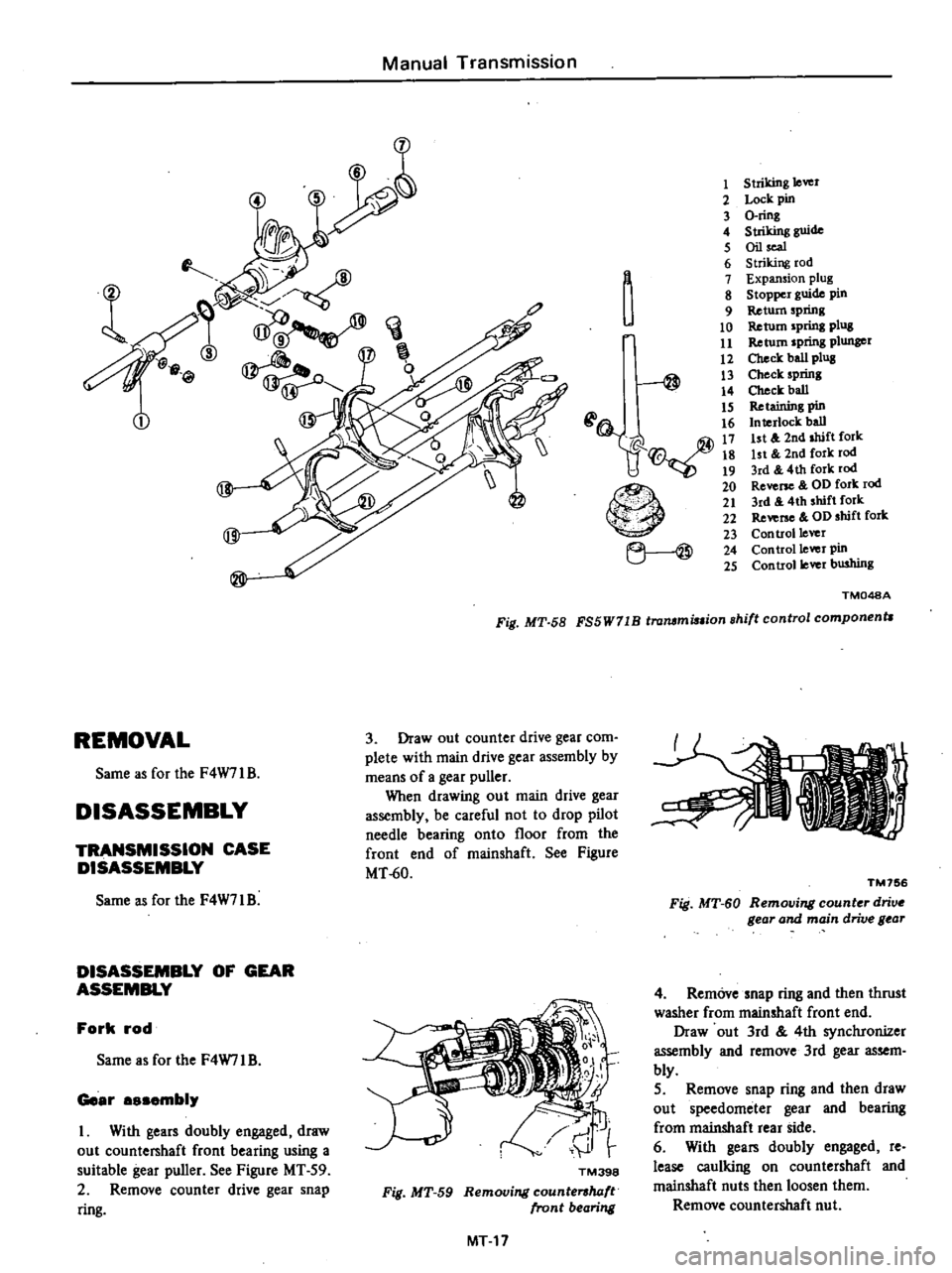
Fig
MT
58
FS5W71B
trammi
ion
shift
control
component
3
Draw
out
counter
drive
gear
com
plete
with
main
drive
gear
assembly
by
means
of
a
gear
puller
When
drawing
out
main
drive
gear
assembly
be
careful
not
to
drop
pilot
needle
bearing
onto
floor
from
the
front
end
of
mainshaft
See
Figure
MT
60
REMOVAL
Same
as
for
the
F4W71B
DISASSEMBLY
TRANSMISSION
CASE
DISASSEMBLY
Same
as
for
the
F4W71
B
DISASSEMBLY
OF
GEAR
ASSEMBLY
Fork
rod
Same
as
for
the
F4W71
B
Geer
sembi
I
With
gears
doubly
engaged
draw
out
counte
haft
front
bearing
using
a
suitable
gear
puller
See
Figure
MT
59
2
Remove
counter
drive
gear
snap
ring
TM398
Fig
MT
59
Removing
countershaft
front
bearing
MT
17
TM756
Fig
MT
60
Removing
counter
drive
gear
and
main
drive
gear
4
Rem6vesnap
ring
and
then
thrust
washer
from
mainshaft
front
end
Draw
out
3rd
4th
synchronizer
assembly
and
remove
3rd
gear
assem
bly
5
Remove
snap
ring
and
then
draw
out
speedometer
gear
and
bearing
from
mainshaft
rear
side
6
With
gea
doubly
engaged
re
lease
caulking
on
countershaft
and
mainshaft
nuts
then
loosen
them
Remove
countershaft
nut
Page 253 of 537
ADAPTER
PLATE
DISASSEMBLY
Same
as
for
the
F4W71
B
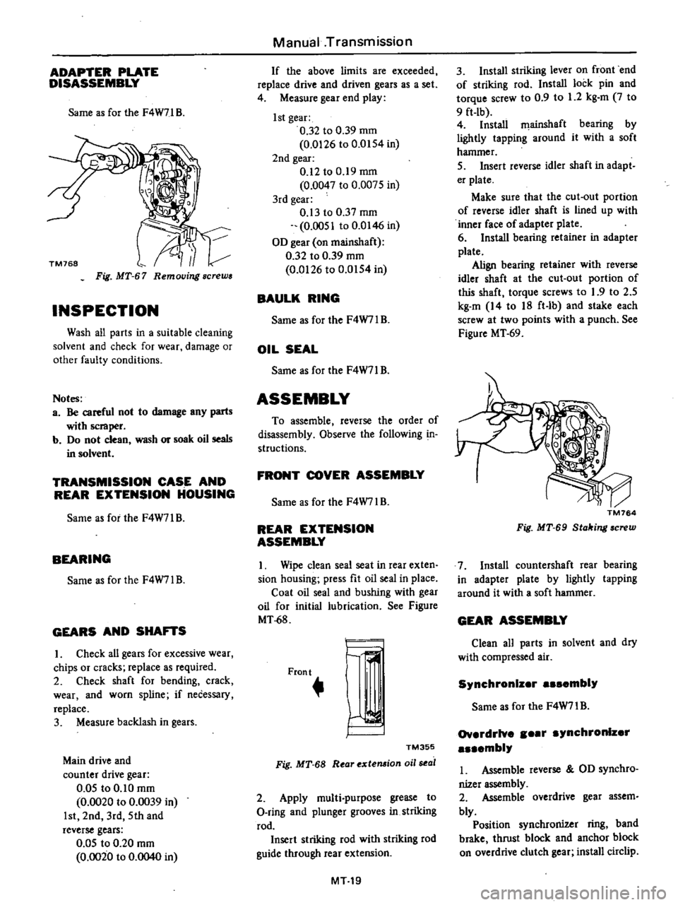
Fig
MT
67
Removing
screws
INSPECTION
Wash
all
parts
in
a
suitable
cleaning
solvent
and
check
for
wear
damage
or
other
faulty
conditions
Notes
a
Be
careful
not
to
damage
any
parts
with
scraper
b
Do
not
clean
wash
or
soak
oil
seals
in
solvent
TRANSMISSION
CASE
AND
REAR
EXTENSION
HOUSING
Same
as
for
the
F4W71
B
BEARING
Same
as
for
the
F4W7l
B
GEARS
AND
SHA
S
I
Check
all
gears
for
excessive
wear
chips
or
cracks
replace
as
required
2
Check
shaft
for
bending
crack
wear
and
worn
spline
if
necessary
replace
3
Measure
backlash
in
gears
Main
drive
and
counter
drive
gear
0
05
to
0
10
mm
0
0020
to
0
0039
in
1st
2nd
3rd
5th
and
reverse
gears
0
05
to
0
20
mm
0
0020
to
0
0040
in
Manual
Transmission
If
the
above
limits
are
exceeded
replace
drive
and
driven
gears
as
a
set
4
Measure
gear
end
play
1st
gear
0
32
to
0
39
mm
0
0126
to
0
0154
in
2nd
gear
0
12
to
0
19
mm
0
0047
to
0
0075
in
3rd
gear
0
13
to
0
37
mm
0
0051
to
0
0146
in
OD
gear
on
mainshaft
0
32
to
0
39
mm
0
0126
to
0
0154
in
BAULK
RING
Same
as
for
the
F4W7IB
OIL
SEAL
Same
as
for
the
F4W71
B
ASSEMBLY
To
assemble
reverse
the
order
of
disassembly
Observe
the
following
in
structions
FRONT
COVER
ASSEMBLY
Same
as
for
the
F4W7l
B
REAR
EXTENSION
ASSEMBLY
I
Wipe
clean
seal
seat
in
rear
exten
sion
housing
press
fit
oil
seal
in
place
Coat
oil
seal
and
bushing
with
gear
oil
for
initial
lubrication
See
Figure
MT
68
Front
r
I
TM355
Fig
MT
68
R
ar
extemion
oil
sea
2
Apply
multi
purpose
grease
to
O
ring
and
plunger
grooves
in
striking
rod
Insert
striking
rod
with
striking
rod
guide
through
rear
extension
MT19
3
Install
striking
lever
on
front
end
of
striking
rod
Install
lock
pin
and
torque
screw
to
0
9
to
1
2
kg
m
7
to
9
ft
lb
4
Install
filainshaft
bearing
by
lightly
tapping
around
it
with
a
soft
hammer
5
Insert
reverse
idler
shaft
in
adapt
er
plate
Make
sure
that
the
cut
out
portion
of
reverse
idler
shaft
is
lined
up
with
inner
face
of
adapter
plate
6
Install
bearing
retainer
in
adapter
plate
Align
bearing
retainer
with
reverse
idler
shaft
at
the
cut
out
portion
of
this
shaft
torque
screws
to
1
9
to
2
5
kg
m
14
to
18
ft
lb
and
stake
each
screw
at
two
points
with
a
punch
See
Figure
MT
69
TM764
Fig
MT
69
Stahing
screw
7
Install
countershaft
rear
bearing
in
adapter
plate
by
lightly
tapping
around
it
with
a
soft
hammer
GEAR
ASSEMBLY
Clean
all
parts
in
solvent
and
dry
with
compressed
air
Synchronlz
r
embly
Same
as
for
the
F4W71
B
Ov
rdrlve
r
ynchronlz
r
mbly
I
Assemble
reverse
OD
synchro
nizer
assembly
2
Assemble
overdrive
gear
assem
bly
Position
synchronizer
ring
band
brake
thrust
block
and
anchor
block
on
overdrive
clutch
gear
install
circlip
Page 256 of 537
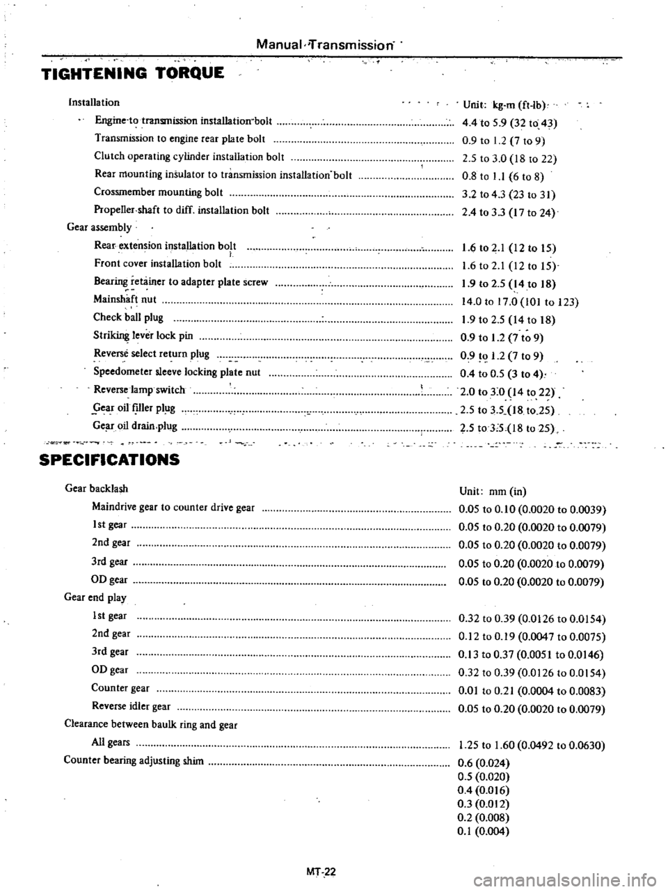
Manual
iTransmission
TIGHTENING
TORQUE
Installa
tion
Engine
to
transmission
installation
bolt
Transmission
to
engine
rear
plate
bolt
Clutch
operating
cylinder
installation
bolt
Rear
mounting
insulator
to
transmission
installation
bolt
Crossmember
mounting
bolt
Propeller
shaft
to
diff
installation
bolt
Gear
assembly
Rear
extension
installation
bolt
Front
cover
installation
bolt
Bearing
retainer
to
adapter
plate
screw
Main
haft
nut
Check
ball
plug
Stri
lever
lock
pin
Reverse
select
return
plug
Speedometer
sleeve
locking
plate
nut
Reverse
lamp
switch
year
oil
Ier
pl
g
Ge
r
oil
drain
plug
Unit
kg
m
ft
lb
4
4
to
5
9
32
to
43
0
9
to
1
2
7
to
9
2
5
to
3
0
18
to
22
0
8
to
1
1
6
to
8
3
2
to
43
23
to
31
2
4
to
33
17
to
24
1
6
to
2
1
12
to
IS
1
6
to
2
1
12to
IS
1
9
to
2
S
14
to
18
14
0
to
17
0
101
to
123
1
9
to
2
S
14
to
18
0
9
to
1
2
7
to
9
0
9
1
2
7
to
9
0
4
to
O
S
3
to
4
2
0
to
3
0
14
to
22
2
S
to
3
5
18
t02S
2
S
toTS
l8
to
2S
or
SPECIFICATIONS
Gear
backlash
Maindrive
gear
to
counter
drive
gear
1st
gear
2nd
gear
3rd
gear
OD
gear
Gear
end
play
1st
gear
2nd
gear
3rd
gear
OD
gear
Counter
gear
Reverse
idler
gear
Clearance
between
baulk
ring
and
gear
All
gears
Counter
bearing
adjusting
shim
Unit
mm
in
0
05
to
0
10
0
0020
to
0
0039
0
05
to
0
20
0
0020
to
0
0079
O
OS
to
0
20
0
0020
to
0
0079
0
05
to
0
20
0
0020
to
0
0079
0
05
to
0
20
0
0020
to
0
0079
0
32
to
0
39
0
0126
to
0
0154
0
12
to
0
19
0
0047
to
0
0075
0
13
to
0
37
0
0051
to
0
0146
0
32
to
0
39
0
0126
to
0
0154
0
01
to
0
21
0
0004
to
0
0083
0
05
to
0
20
0
0020
to
0
0079
1
25
to
1
60
0
0492
to
0
0630
0
6
0
024
0
5
0
020
0
4
0
016
0
3
0
012
0
2
0
008
0
1
0
004
MT
22
Page 257 of 537
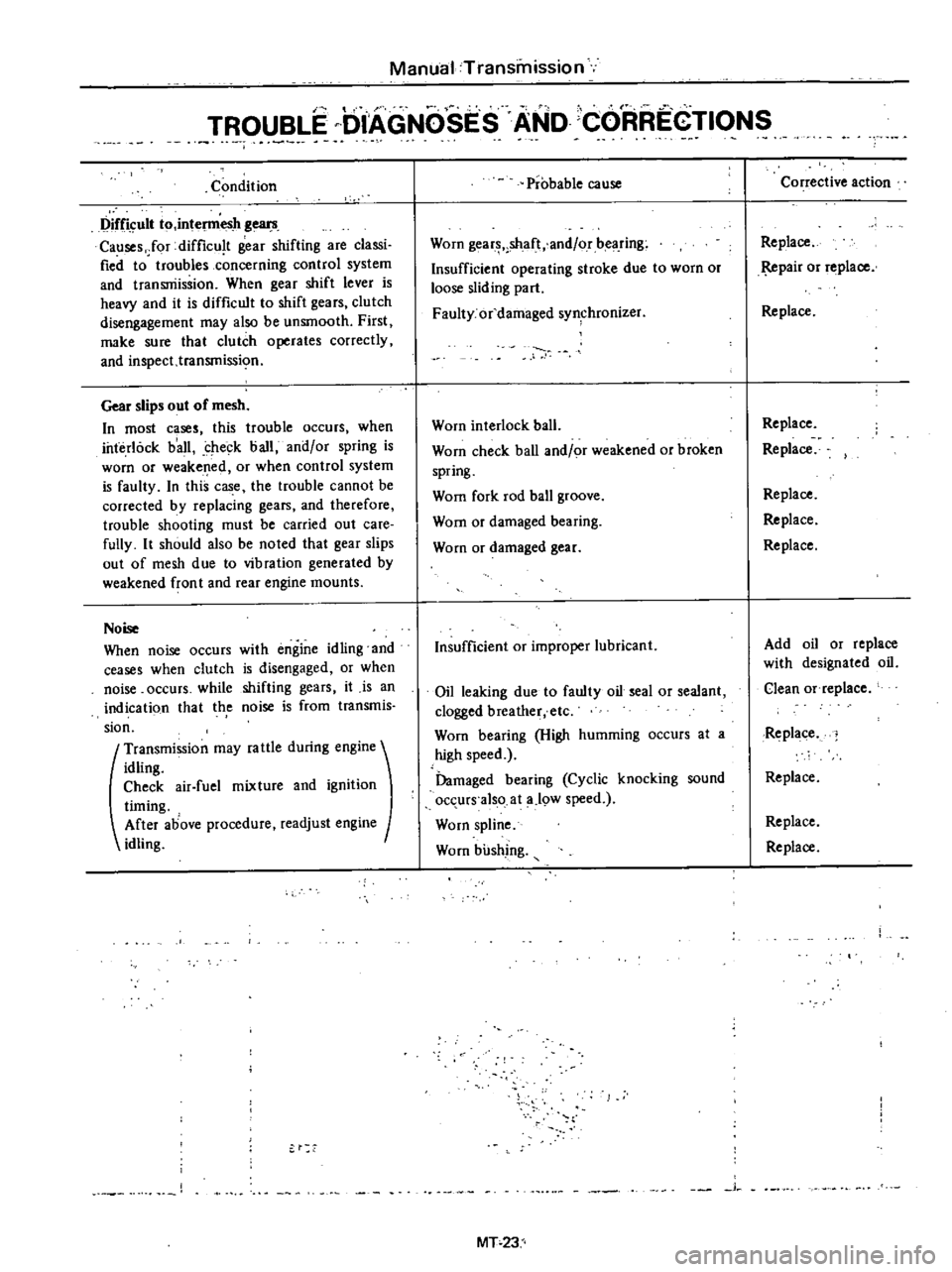
Manual
Transmission
I
TROUBLE
DIAGNOSES
AND
CORREGTIONS
Condition
Difficult
to
intel11lesh
gears
Causes
Jor
difficu
t
gear
shifting
are
classi
fied
to
troubles
concerning
control
system
and
transniissioo
When
gear
shift
lever
is
heavy
and
it
is
difficult
to
shift
gears
clutch
disengagement
may
also
be
unsmooth
First
make
sure
that
clutch
operates
correctly
and
inspect
transmissi
o
Gear
slips
out
of
mesh
In
most
cases
this
trouble
occurs
when
interlock
b
all
check
ball
and
or
spring
is
worn
or
weakened
or
when
control
system
is
faulty
In
this
case
the
trouble
cannot
be
corrected
by
replacing
gears
and
therefore
trouble
shooting
must
be
carried
out
care
fully
It
should
also
be
noted
that
gear
slips
out
of
mesh
due
to
vibration
generated
by
weakened
fron
t
and
rear
engine
mounts
Noise
When
noise
occurs
with
engine
idling
and
ceases
when
clutch
is
disengaged
or
when
noise
occurs
while
shifting
gears
it
is
an
indicati90
that
th
e
noise
is
from
transmis
sion
t
Transmission
may
fa
ule
during
engine
idling
Check
air
fuel
mixture
and
ignition
timing
After
above
procedure
readjust
engine
idling
Probable
cause
Worn
gear
shaft
and
or
bearing
Insufficient
operating
stroke
due
to
worn
or
loose
sliding
part
Faulty
or
damaged
synchronizer
Worn
interlock
ball
Worn
check
ball
and
or
weakened
or
broken
spring
Wom
fork
rod
ball
groove
Wom
or
damaged
bearing
Worn
or
damaged
gear
Insufficient
or
improper
lubricant
Oil
leaking
due
to
faulty
oil
seal
or
sealant
clogged
breather
etc
Worn
bearing
High
humming
occurs
at
a
high
speed
Damaged
bearing
Cyclic
knocking
sound
occurs
also
at
a
19W
speed
Worn
spline
Worn
bushing
j
MT
23
Corrective
action
Replace
pair
or
replace
Replace
Replace
Replace
Replace
Replace
Replace
Add
oil
or
replace
with
designated
oil
Clean
Of
replace
Replace
Replace
Replace
Replace