tow DODGE DURANGO 2021 Manual Online
[x] Cancel search | Manufacturer: DODGE, Model Year: 2021, Model line: DURANGO, Model: DODGE DURANGO 2021Pages: 340, PDF Size: 20.38 MB
Page 272 of 340
270SERVICING AND MAINTENANCE
CHECKING OIL LEVEL
To ensure proper engine lubrication, the engine oil
must be maintained at the correct level. Check the oil
level at regular intervals, such as every fuel stop. The
best time to check the engine oil level is about five
minutes after a fully warmed up engine is shut off.
Checking the oil while the vehicle is on level ground
will improve the accuracy of the oil level readings.
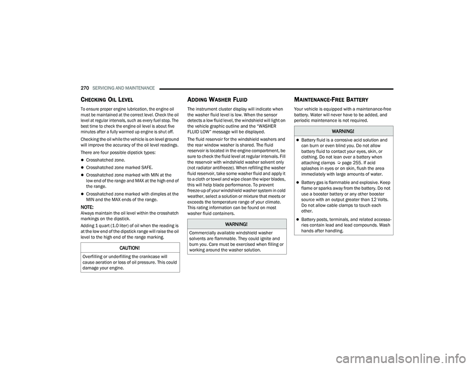
There are four possible dipstick types:
Crosshatched zone.
Crosshatched zone marked SAFE.
Crosshatched zone marked with MIN at the
low end of the range and MAX at the high end of
the range.
Crosshatched zone marked with dimples at the
MIN and the MAX ends of the range.
NOTE:Always maintain the oil level within the crosshatch
markings on the dipstick.
Adding 1 quart (1.0 liter) of oil when the reading is
at the low end of the dipstick range will raise the oil
level to the high end of the range marking.
ADDING WASHER FLUID
The instrument cluster display will indicate when
the washer fluid level is low. When the sensor
detects a low fluid level, the windshield will light on
the vehicle graphic outline and the “WASHER
FLUID LOW” message will be displayed.
The fluid reservoir for the windshield washers and
the rear window washer is shared. The fluid
reservoir is located in the engine compartment, be
sure to check the fluid level at regular intervals. Fill
the reservoir with windshield washer solvent only
(not radiator antifreeze). When refilling the washer
fluid reservoir, take some washer fluid and apply it
to a cloth or towel and wipe clean the wiper blades,
this will help blade performance. To prevent
freeze-up of your windshield washer system in cold
weather, select a solution or mixture that meets or
exceeds the temperature range of your climate.
This rating information can be found on most
washer fluid containers.
MAINTENANCE-FREE BATTERY
Your vehicle is equipped with a maintenance-free
battery. Water will never have to be added, and
periodic maintenance is not required.
CAUTION!
Overfilling or underfilling the crankcase will
cause aeration or loss of oil pressure. This could
damage your engine.
WARNING!
Commercially available windshield washer
solvents are flammable. They could ignite and
burn you. Care must be exercised when filling or
working around the washer solution.
WARNING!
Battery fluid is a corrosive acid solution and
can burn or even blind you. Do not allow
battery fluid to contact your eyes, skin, or
clothing. Do not lean over a battery when
attaching clamps Úpage 255. If acid
splashes in eyes or on skin, flush the area
immediately with large amounts of water.
Battery gas is flammable and explosive. Keep
flame or sparks away from the battery. Do not
use a booster battery or any other booster
source with an output greater than 12 Volts.
Do not allow cable clamps to touch each
other.
Battery posts, terminals, and related accesso -
ries contain lead and lead compounds. Wash
hands after handling.
21_WD_OM_EN_USC_t.book Page 270
Page 276 of 340
274SERVICING AND MAINTENANCE
Refrigerant Recovery And Recycling
R-134a — If Equipped
R-134a Air Conditioning Refrigerant is a Hydrofluo -
rocarbon (HFC) that is an ozone-friendly
substance. The manufacturer recommends that
air conditioning service be performed by an
authorized dealer or other service facilities using
recovery and recycling equipment.
NOTE:Use only the manufacturer approved A/C system
PAG compressor oil and refrigerants.
Refrigerant Recovery And Recycling
R-1234yf — If Equipped
R-1234yf Air Conditioning Refrigerant is a Hydroflu -
oroolefin (HFO) that is endorsed by the
Environmental Protection Agency and is an
ozone-friendly substance with a low global-warming potential. The manufacturer
recommends that air conditioning service be
performed by an authorized dealer using recovery
and recycling equipment.
NOTE:Use only the manufacturer approved A/C system
PAG compressor oil, and refrigerants.
Cabin Air Filter
For the proper maintenance intervals
Úpage 265.
The cabin air filter is located in the fresh air inlet
behind the glove compartment. Perform the
following procedure to replace the filter:
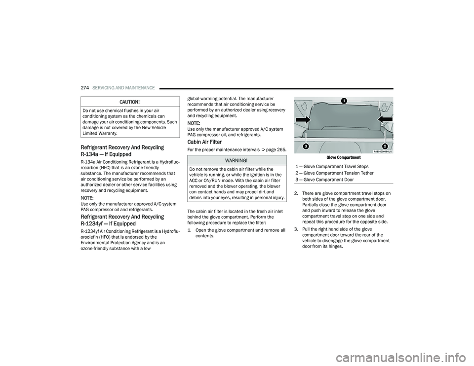
1. Open the glove compartment and remove all contents.
Glove Compartment
2. There are glove compartment travel stops on both sides of the glove compartment door.
Partially close the glove compartment door
and push inward to release the glove
compartment travel stop on one side and
repeat this procedure for the opposite side.
3. Pull the right hand side of the glove compartment door toward the rear of the
vehicle to disengage the glove compartment
door from its hinges.
CAUTION!
Do not use chemical flushes in your air
conditioning system as the chemicals can
damage your air conditioning components. Such
damage is not covered by the New Vehicle
Limited Warranty.
WARNING!
Do not remove the cabin air filter while the
vehicle is running, or while the ignition is in the
ACC or ON/RUN mode. With the cabin air filter
removed and the blower operating, the blower
can contact hands and may propel dirt and
debris into your eyes, resulting in personal injury.1 — Glove Compartment Travel Stops
2 — Glove Compartment Tension Tether
3 — Glove Compartment Door
21_WD_OM_EN_USC_t.book Page 274
Page 277 of 340
SERVICING AND MAINTENANCE275
NOTE:When disengaging the glove compartment door
from its hinges, there will be some resistance.
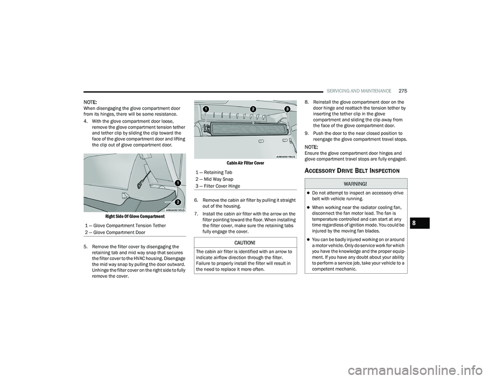
4. With the glove compartment door loose,
remove the glove compartment tension tether
and tether clip by sliding the clip toward the
face of the glove compartment door and lifting
the clip out of glove compartment door.
Right Side Of Glove Compartment
5. Remove the filter cover by disengaging the retaining tab and mid way snap that secures
the filter cover to the HVAC housing. Disengage
the mid way snap by pulling the door outward.
Unhinge the filter cover on the right side to fully
remove the cover.
Cabin Air Filter Cover
6. Remove the cabin air filter by pulling it straight out of the housing.
7. Install the cabin air filter with the arrow on the filter pointing toward the floor. When installing
the filter cover, make sure the retaining tabs
fully engage the cover. 8. Reinstall the glove compartment door on the
door hinge and reattach the tension tether by
inserting the tether clip in the glove
compartment and sliding the clip away from
the face of the glove compartment door.
9. Push the door to the near closed position to reengage the glove compartment travel stops.
NOTE:Ensure the glove compartment door hinges and
glove compartment travel stops are fully engaged.
ACCESSORY DRIVE BELT INSPECTION
1 — Glove Compartment Tension Tether
2 — Glove Compartment Door
1 — Retaining Tab
2 — Mid Way Snap
3 — Filter Cover Hinge
CAUTION!
The cabin air filter is identified with an arrow to
indicate airflow direction through the filter.
Failure to properly install the filter will result in
the need to replace it more often.
WARNING!
Do not attempt to inspect an accessory drive
belt with vehicle running.
When working near the radiator cooling fan,
disconnect the fan motor lead. The fan is
temperature controlled and can start at any
time regardless of ignition mode. You could be
injured by the moving fan blades.
You can be badly injured working on or around
a motor vehicle. Only do service work for which
you have the knowledge and the proper equip -
ment. If you have any doubt about your ability
to perform a service job, take your vehicle to a
competent mechanic.
8
21_WD_OM_EN_USC_t.book Page 275
Page 279 of 340
SERVICING AND MAINTENANCE277
The wiper blades and wiper arms should be
inspected periodically, not just when wiper
performance problems are experienced. This
inspection should include the following points:
Wear or uneven edges
Foreign material
Hardening or cracking
Deformation or fatigue
If a wiper blade or wiper arm is damaged, replace
the affected wiper arm or blade with a new unit. Do
not attempt to repair a wiper arm or blade that is
damaged.
Front Wiper Blade Removal/Installation
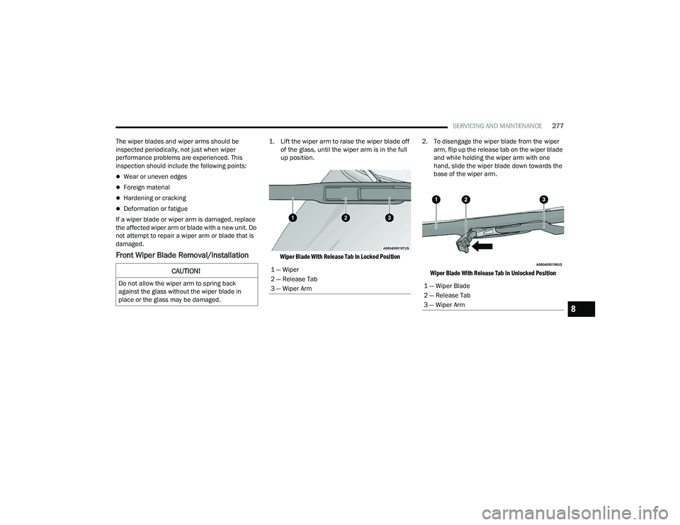
1. Lift the wiper arm to raise the wiper blade off of the glass, until the wiper arm is in the full
up position.
Wiper Blade With Release Tab In Locked Position
2. To disengage the wiper blade from the wiper
arm, flip up the release tab on the wiper blade
and while holding the wiper arm with one
hand, slide the wiper blade down towards the
base of the wiper arm.
Wiper Blade With Release Tab In Unlocked Position
CAUTION!
Do not allow the wiper arm to spring back
against the glass without the wiper blade in
place or the glass may be damaged.
1 — Wiper
2 — Release Tab
3 — Wiper Arm
1 — Wiper Blade
2 — Release Tab
3 — Wiper Arm
8
21_WD_OM_EN_USC_t.book Page 277
Page 280 of 340
278SERVICING AND MAINTENANCE
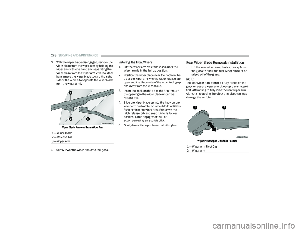
3. With the wiper blade disengaged, remove the wiper blade from the wiper arm by holding the
wiper arm with one hand and separating the
wiper blade from the wiper arm with the other
hand (move the wiper blade toward the right
side of the vehicle to separate the wiper blade
from the wiper arm).
Wiper Blade Removed From Wiper Arm
4. Gently lower the wiper arm onto the glass. Installing The Front Wipers
1. Lift the wiper arm off of the glass, until the
wiper arm is in the full up position.
2. Position the wiper blade near the hook on the tip of the wiper arm with the wiper release tab
open and the blade side of the wiper facing up
and away from the windshield.
3. Insert the hook on the tip of the arm through the opening in the wiper blade under the
release tab.
4. Slide the wiper blade up into the hook on the wiper arm and rotate the wiper blade until it is
flush against the wiper arm. Fold down the
latch release tab and snap it into its locked
position. Latch engagement will be
accompanied by an audible click.
5. Gently lower the wiper blade onto the glass.
Rear Wiper Blade Removal/Installation
1. Lift the rear wiper arm pivot cap away from the glass to allow the rear wiper blade to be
raised off of the glass.
NOTE:The rear wiper arm cannot be fully raised off the
glass unless the wiper arm pivot cap is unsnapped
first. Attempting to fully raise the rear wiper arm
without unsnapping the wiper arm pivot cap may
damage the vehicle.
Wiper Pivot Cap In Unlocked Position
1 — Wiper Blade
2 — Release Tab
3 — Wiper Arm
1 — Wiper Arm Pivot Cap
2 — Wiper Arm
21_WD_OM_EN_USC_t.book Page 278
Page 282 of 340
280SERVICING AND MAINTENANCE
(Continued)
(Continued)
deteriorated, or mispositioned parts. Open seams
or loose connections could permit exhaust fumes
to seep into the passenger compartment. In
addition, have the exhaust system inspected each
time the vehicle is raised for lubrication or oil
change. Replace as required.
Under normal operating conditions, the catalytic
converter will not require maintenance. However, it
is important to keep the engine properly tuned to
ensure proper catalyst operation and prevent
possible catalyst damage.
NOTE:Intentional tampering with emissions control
systems can result in civil penalties being
assessed against you.
In unusual situations involving grossly
malfunctioning engine operation, a scorching odor
may suggest severe and abnormal catalyst
overheating. If this occurs, stop the vehicle, turn off
the engine and allow it to cool. Service, including a
tune-up to the manufacturer's specifications,
should be obtained immediately.To minimize the possibility of catalytic converter
damage:
Do not interrupt the ignition when the transmis
-
sion is in gear and the vehicle is in motion.
Do not try to start the vehicle by pushing or
towing the vehicle.
Do not idle the engine with any ignition compo -
nents disconnected or removed, such as when
diagnostic testing, or for prolonged periods
during very rough idle or malfunctioning oper -
ating conditions.
COOLING SYSTEM
WARNING!
Exhaust gases can injure or kill. They contain
Carbon Monoxide (CO), which is colorless and
odorless. Breathing it can make you uncon -
scious and can eventually poison you. To
avoid breathing CO see Ú page 239.
A hot exhaust system can start a fire if you
park over materials that can burn. Such mate -
rials might be grass or leaves coming into
contact with your exhaust system. Do not park
or operate your vehicle in areas where your
exhaust system can contact anything that
can burn.
CAUTION!
The catalytic converter requires the use of
unleaded fuel only. Leaded gasoline will
destroy the effectiveness of the catalyst as an
emissions control device and may seriously
reduce engine performance and cause
serious damage to the engine.
Damage to the catalytic converter can result if
your vehicle is not kept in proper operating
condition. In the event of engine malfunction,
particularly involving engine misfire or other
apparent loss of performance, have your
vehicle serviced promptly. Continued opera -
tion of your vehicle with a severe malfunction
could cause the converter to overheat,
resulting in possible damage to the converter
and vehicle.
CAUTION!
WARNING!
You or others can be badly burned by hot
engine coolant (antifreeze) or steam from your
radiator. If you see or hear steam coming from
under the hood, do not open the hood until the
radiator has had time to cool. Never open a
cooling system pressure cap when the radi -
ator or coolant bottle is hot.
Keep hands, tools, clothing, and jewelry away
from the radiator cooling fan when the hood is
raised. The fan starts automatically and may
start at any time, whether the engine is
running or not.
21_WD_OM_EN_USC_t.book Page 280
Page 289 of 340
SERVICING AND MAINTENANCE287
Underhood Fuses
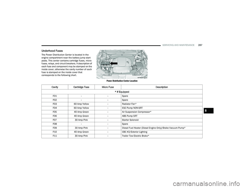
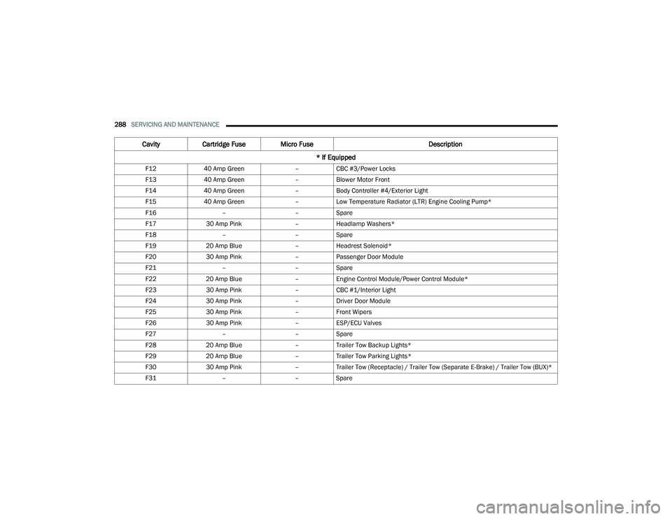
The Power Distribution Center is located in the
engine compartment near the battery jump start
posts. This center contains cartridge fuses, micro
fuses, relays, and circuit breakers. A description of
each fuse and component may be stamped on the
inside cover, otherwise the cavity number of each
fuse is stamped on the inside cover that
corresponds to the following chart.
Power Distribution Center Location
CavityCartridge Fuse Micro Fuse Description
* If Equipped
F01 ––Spare
F02 ––Spare
F03 60 Amp Yellow –Radiator Fan*
F04 60 Amp Yellow –ESC Pump NON-SRT
F05 40 Amp Green –Air Suspension Compressor*
F06 40 Amp Green –ABS Pump SRT
F07 30 Amp Pink –Starter Solenoid
F08 ––Spare
F09 30 Amp Pink –Diesel Fuel Heater (Diesel Engine Only)/Brake Vacuum Pump*
F10 40 Amp Green –CBC #2/Exterior Lighting
F11 30 Amp Pink –Trailer Tow Electric Brake*
8
21_WD_OM_EN_USC_t.book Page 287
Page 290 of 340
288SERVICING AND MAINTENANCE
F12 40 Amp Green –CBC #3/Power Locks
F13 40 Amp Green –Blower Motor Front
F14 40 Amp Green –Body Controller #4/Exterior Light
F15 40 Amp Green –Low Temperature Radiator (LTR) Engine Cooling Pump*
F16 ––Spare
F17 30 Amp Pink –Headlamp Washers*
F18 ––Spare
F19 20 Amp Blue –Headrest Solenoid*
F20 30 Amp Pink –Passenger Door Module
F21 ––Spare
F22 20 Amp Blue –Engine Control Module/Power Control Module*
F23 30 Amp Pink –CBC #1/Interior Light
F24 30 Amp Pink –Driver Door Module
F25 30 Amp Pink –Front Wipers
F26 30 Amp Pink –ESP/ECU Valves
F27 ––Spare
F28 20 Amp Blue –Trailer Tow Backup Lights*
F29 20 Amp Blue –Trailer Tow Parking Lights*
F30 30 Amp Pink –Trailer Tow (Receptacle) / Trailer Tow (Separate E-Brake) / Trailer Tow (BUX)*
F31 ––Spare
Cavity Cartridge Fuse Micro Fuse Description
* If Equipped
21_WD_OM_EN_USC_t.book Page 288
Page 292 of 340
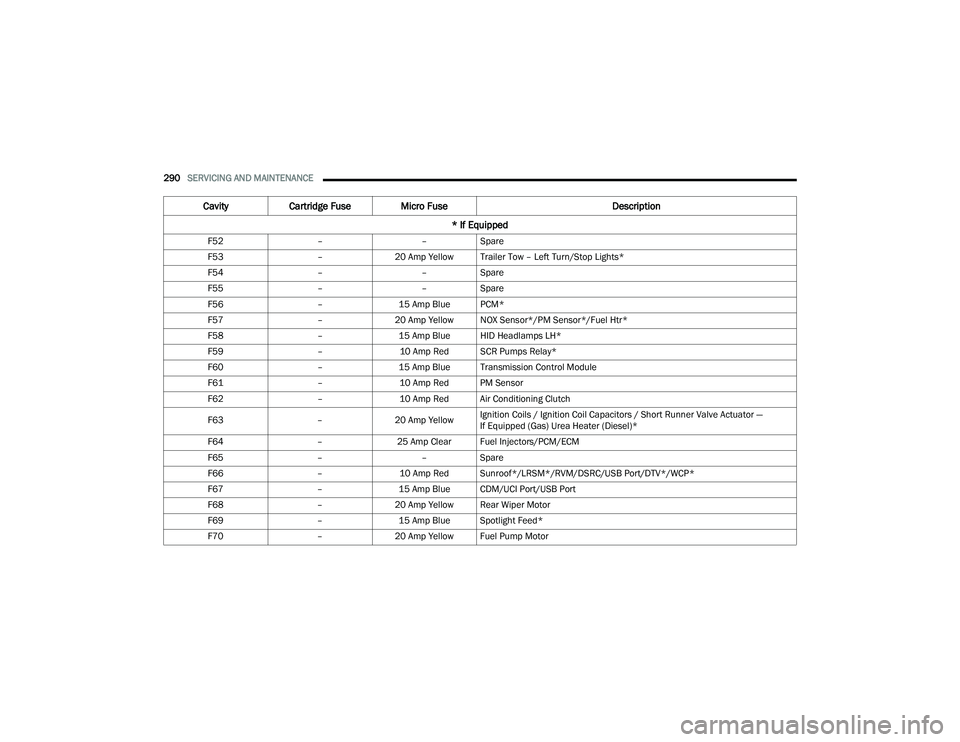
290SERVICING AND MAINTENANCE
F52 ––Spare
F53 –20 Amp Yellow Trailer Tow – Left Turn/Stop Lights*
F54 ––Spare
F55 ––Spare
F56 –15 Amp Blue PCM*
F57 –20 Amp Yellow NOX Sensor*/PM Sensor*/Fuel Htr*
F58 –15 Amp Blue HID Headlamps LH*
F59 –10 Amp Red SCR Pumps Relay*
F60 –15 Amp Blue Transmission Control Module
F61 –10 Amp Red PM Sensor
F62 –10 Amp Red Air Conditioning Clutch
F63 –20 Amp Yellow Ignition Coils / Ignition Coil Capacitors / Short Runner Valve Actuator —
If Equipped (Gas) Urea Heater (Diesel)*
F64 –25 Amp Clear Fuel Injectors/PCM/ECM
F65 ––Spare
F66 –10 Amp Red Sunroof*/LRSM*/RVM/DSRC/USB Port/DTV*/WCP*
F67 –15 Amp Blue CDM/UCI Port/USB Port
F68 –20 Amp Yellow Rear Wiper Motor
F69 –15 Amp Blue Spotlight Feed*
F70 –20 Amp Yellow Fuel Pump Motor
Cavity Cartridge Fuse Micro Fuse Description
* If Equipped
21_WD_OM_EN_USC_t.book Page 290
Page 293 of 340
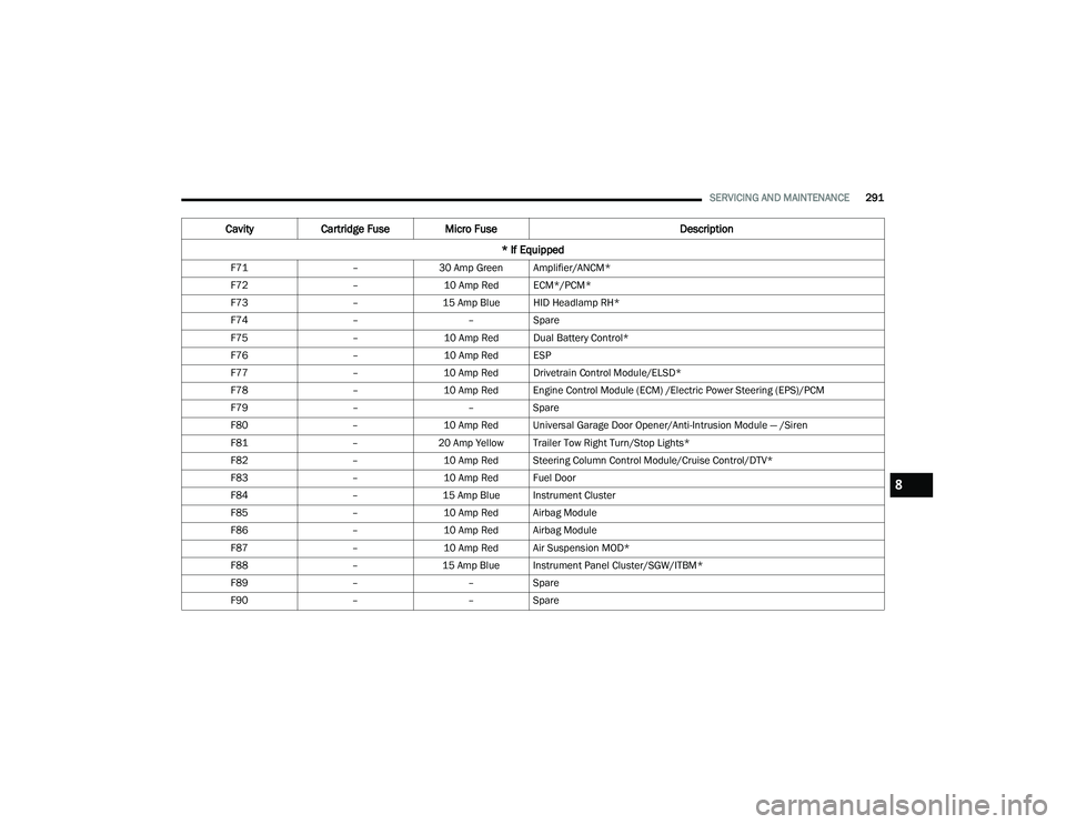
SERVICING AND MAINTENANCE291
F71 –30 Amp Green Amplifier/ANCM*
F72 –10 Amp Red ECM*/PCM*
F73 –15 Amp Blue HID Headlamp RH*
F74 ––Spare
F75 –10 Amp Red Dual Battery Control*
F76 –10 Amp Red ESP
F77 –10 Amp Red Drivetrain Control Module/ELSD*
F78 –10 Amp Red Engine Control Module (ECM) /Electric Power Steering (EPS)/PCM
F79 ––Spare
F80 –10 Amp Red Universal Garage Door Opener/Anti-Intrusion Module — /Siren
F81 –20 Amp Yellow Trailer Tow Right Turn/Stop Lights*
F82 –10 Amp Red Steering Column Control Module/Cruise Control/DTV*
F83 –10 Amp Red Fuel Door
F84 –15 Amp Blue Instrument Cluster
F85 –10 Amp Red Airbag Module
F86 –10 Amp Red Airbag Module
F87 –10 Amp Red Air Suspension MOD*
F88 –15 Amp Blue Instrument Panel Cluster/SGW/ITBM*
F89 ––Spare
F90 ––Spare
Cavity Cartridge Fuse Micro Fuse Description
* If Equipped
8
21_WD_OM_EN_USC_t.book Page 291