DODGE NEON 1999 Service Owner's Guide
Manufacturer: DODGE, Model Year: 1999, Model line: NEON, Model: DODGE NEON 1999Pages: 1200, PDF Size: 35.29 MB
Page 31 of 1200
CAUTION: The steering knuckle to strut assembly
attaching bolts are serrated and must not be turned
during removal. Remove nuts while holding bolts
stationary in the steering knuckles.
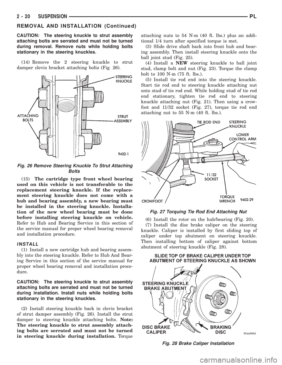
(14) Remove the 2 steering knuckle to strut
damper clevis bracket attaching bolts (Fig. 26).
(15)The cartridge type front wheel bearing
used on this vehicle is not transferable to the
replacement steering knuckle. If the replace-
ment steering knuckle does not come with a
hub and bearing assembly, a new bearing must
be installed in the steering knuckle. Installa-
tion of the new wheel bearing must be done
before installing steering knuckle on vehicle.
Refer to Hub and Bearing Service in this section of
the service manual for proper wheel bearing removal
and installation procedure.
INSTALL
(1) Install a new cartridge hub and bearing assem-
bly into the steering knuckle. Refer to Hub And Bear-
ing Service in this section of the service manual for
proper wheel bearing removal and installation proce-
dure.
CAUTION: The steering knuckle to strut assembly
attaching bolts are serrated and must not be turned
during installation. Install nuts while holding bolts
stationary in the steering knuckles.
(2) Install steering knuckle back in clevis bracket
of strut damper assembly (Fig. 26). Install the strut
damper to steering knuckle attaching bolts.Note:
The steering knuckle to strut assembly attach-
ing bolts are serrated and must not be turned
in steering knuckle during installation.Torqueattaching nuts to 54 N´m (40 ft. lbs.) plus an addi-
tional 1/4 turn after specified torque is met.
(3) Slide drive shaft back into front hub and bear-
ing assembly. Then install steering knuckle onto the
ball joint stud (Fig. 25).
(4) Install aNEWsteering knuckle to ball joint
stud, clamp bolt and nut (Fig. 23). Torque the clamp
bolt to 100 N´m (75 ft. lbs.).
(5) Install tie rod end into the steering knuckle.
Start tie rod end to steering knuckle attaching nut
onto stud of tie rod end. While holding stud of tie rod
end stationary, tighten tie rod end to steering
knuckle attaching nut (Fig. 21). Then using a crow-
foot and 11/32 socket (Fig. 27), torque tie rod end
attaching nut to 55 N´m (40 ft. lbs.).
(6) Install the rotor on the hub/bearing (Fig. 20).
(7) Install the disc brake caliper on the steering
knuckle. Caliper is installed by first sliding top of
caliper under top abutment on steering knuckle.
Then installing bottom of caliper against bottom
abutment of steering knuckle (Fig. 28).
Fig. 28 Brake Caliper Installation
Fig. 26 Remove Steering Knuckle To Strut Attaching
Bolts
Fig. 27 Torquing Tie Rod End Attaching Nut
2 - 20 SUSPENSIONPL
REMOVAL AND INSTALLATION (Continued)
Page 32 of 1200
(8) Install the disc brake caliper to steering
knuckle attaching bolts (Fig. 17). Tighten the caliper
attaching bolts to a torque of 31 N´m (23 ft. lbs.).
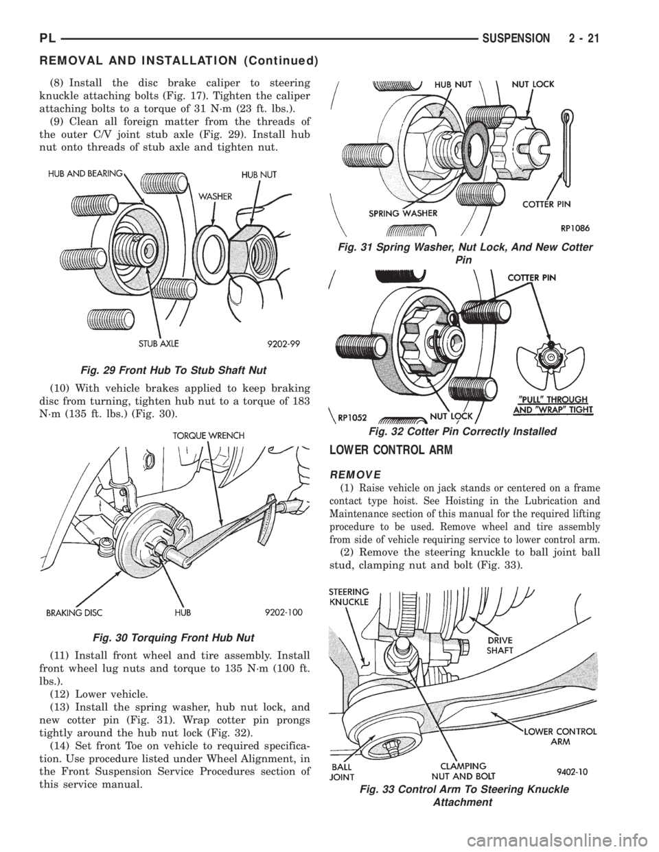
(9) Clean all foreign matter from the threads of
the outer C/V joint stub axle (Fig. 29). Install hub
nut onto threads of stub axle and tighten nut.
(10) With vehicle brakes applied to keep braking
disc from turning, tighten hub nut to a torque of 183
N´m (135 ft. lbs.) (Fig. 30).
(11) Install front wheel and tire assembly. Install
front wheel lug nuts and torque to 135 N´m (100 ft.
lbs.).
(12) Lower vehicle.
(13) Install the spring washer, hub nut lock, and
new cotter pin (Fig. 31). Wrap cotter pin prongs
tightly around the hub nut lock (Fig. 32).
(14) Set front Toe on vehicle to required specifica-
tion. Use procedure listed under Wheel Alignment, in
the Front Suspension Service Procedures section of
this service manual.
LOWER CONTROL ARM
REMOVE
(1)Raise vehicle on jack stands or centered on a frame
contact type hoist. See Hoisting in the Lubrication and
Maintenance section of this manual for the required lifting
procedure to be used. Remove wheel and tire assembly
from side of vehicle requiring service to lower control arm.
(2) Remove the steering knuckle to ball joint ball
stud, clamping nut and bolt (Fig. 33).
Fig. 29 Front Hub To Stub Shaft Nut
Fig. 30 Torquing Front Hub Nut
Fig. 31 Spring Washer, Nut Lock, And New Cotter
Pin
Fig. 32 Cotter Pin Correctly Installed
Fig. 33 Control Arm To Steering Knuckle
Attachment
PLSUSPENSION 2 - 21
REMOVAL AND INSTALLATION (Continued)
Page 33 of 1200
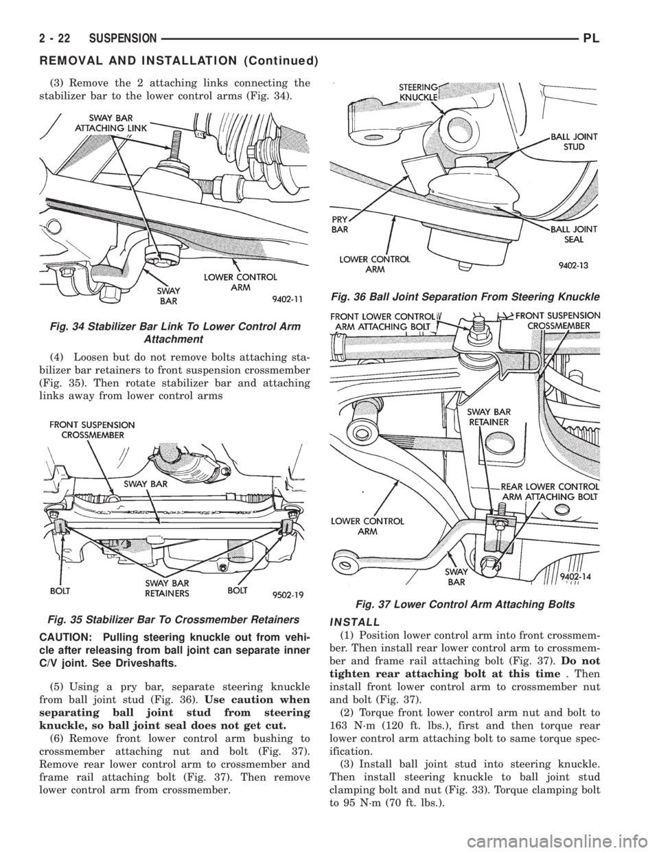
(3) Remove the 2 attaching links connecting the
stabilizer bar to the lower control arms (Fig. 34).
(4) Loosen but do not remove bolts attaching sta-
bilizer bar retainers to front suspension crossmember
(Fig. 35). Then rotate stabilizer bar and attaching
links away from lower control arms
CAUTION: Pulling steering knuckle out from vehi-
cle after releasing from ball joint can separate inner
C/V joint. See Driveshafts.
(5) Using a pry bar, separate steering knuckle
from ball joint stud (Fig. 36).Use caution when
separating ball joint stud from steering
knuckle, so ball joint seal does not get cut.
(6) Remove front lower control arm bushing to
crossmember attaching nut and bolt (Fig. 37).
Remove rear lower control arm to crossmember and
frame rail attaching bolt (Fig. 37). Then remove
lower control arm from crossmember.
INSTALL
(1) Position lower control arm into front crossmem-
ber. Then install rear lower control arm to crossmem-
ber and frame rail attaching bolt (Fig. 37).Do not
tighten rear attaching bolt at this time. Then
install front lower control arm to crossmember nut
and bolt (Fig. 37).
(2) Torque front lower control arm nut and bolt to
163 N´m (120 ft. lbs.), first and then torque rear
lower control arm attaching bolt to same torque spec-
ification.
(3) Install ball joint stud into steering knuckle.
Then install steering knuckle to ball joint stud
clamping bolt and nut (Fig. 33). Torque clamping bolt
to 95 N´m (70 ft. lbs.).
Fig. 34 Stabilizer Bar Link To Lower Control Arm
Attachment
Fig. 35 Stabilizer Bar To Crossmember Retainers
Fig. 36 Ball Joint Separation From Steering Knuckle
Fig. 37 Lower Control Arm Attaching Bolts
2 - 22 SUSPENSIONPL
REMOVAL AND INSTALLATION (Continued)
Page 34 of 1200
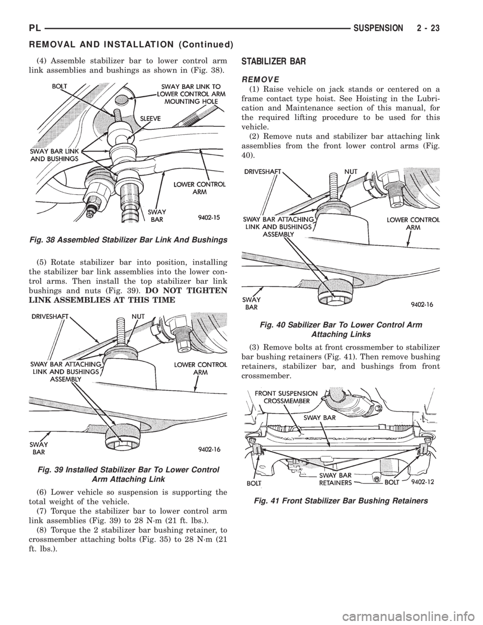
(4) Assemble stabilizer bar to lower control arm
link assemblies and bushings as shown in (Fig. 38).
(5) Rotate stabilizer bar into position, installing
the stabilizer bar link assemblies into the lower con-
trol arms. Then install the top stabilizer bar link
bushings and nuts (Fig. 39).DO NOT TIGHTEN
LINK ASSEMBLIES AT THIS TIME
(6) Lower vehicle so suspension is supporting the
total weight of the vehicle.
(7) Torque the stabilizer bar to lower control arm
link assemblies (Fig. 39) to 28 N´m (21 ft. lbs.).
(8) Torque the 2 stabilizer bar bushing retainer, to
crossmember attaching bolts (Fig. 35) to 28 N´m (21
ft. lbs.).STABILIZER BAR
REMOVE
(1) Raise vehicle on jack stands or centered on a
frame contact type hoist. See Hoisting in the Lubri-
cation and Maintenance section of this manual, for
the required lifting procedure to be used for this
vehicle.
(2) Remove nuts and stabilizer bar attaching link
assemblies from the front lower control arms (Fig.
40).
(3) Remove bolts at front crossmember to stabilizer
bar bushing retainers (Fig. 41). Then remove bushing
retainers, stabilizer bar, and bushings from front
crossmember.
Fig. 38 Assembled Stabilizer Bar Link And Bushings
Fig. 39 Installed Stabilizer Bar To Lower Control
Arm Attaching Link
Fig. 40 Sabilizer Bar To Lower Control Arm
Attaching Links
Fig. 41 Front Stabilizer Bar Bushing Retainers
PLSUSPENSION 2 - 23
REMOVAL AND INSTALLATION (Continued)
Page 35 of 1200
INSTALL
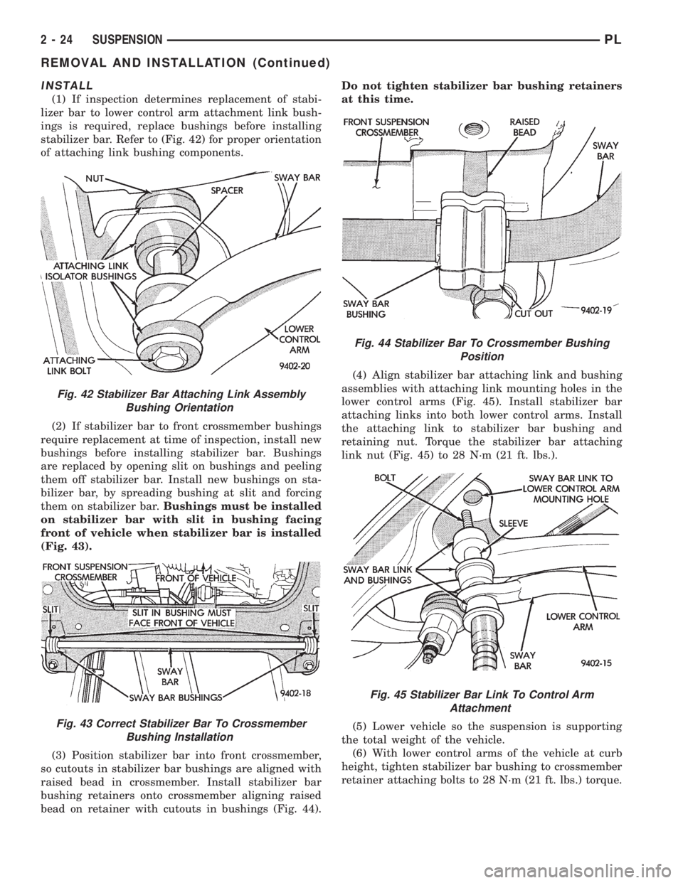
(1) If inspection determines replacement of stabi-
lizer bar to lower control arm attachment link bush-
ings is required, replace bushings before installing
stabilizer bar. Refer to (Fig. 42) for proper orientation
of attaching link bushing components.
(2) If stabilizer bar to front crossmember bushings
require replacement at time of inspection, install new
bushings before installing stabilizer bar. Bushings
are replaced by opening slit on bushings and peeling
them off stabilizer bar. Install new bushings on sta-
bilizer bar, by spreading bushing at slit and forcing
them on stabilizer bar.Bushings must be installed
on stabilizer bar with slit in bushing facing
front of vehicle when stabilizer bar is installed
(Fig. 43).
(3) Position stabilizer bar into front crossmember,
so cutouts in stabilizer bar bushings are aligned with
raised bead in crossmember. Install stabilizer bar
bushing retainers onto crossmember aligning raised
bead on retainer with cutouts in bushings (Fig. 44).Do not tighten stabilizer bar bushing retainers
at this time.
(4) Align stabilizer bar attaching link and bushing
assemblies with attaching link mounting holes in the
lower control arms (Fig. 45). Install stabilizer bar
attaching links into both lower control arms. Install
the attaching link to stabilizer bar bushing and
retaining nut. Torque the stabilizer bar attaching
link nut (Fig. 45) to 28 N´m (21 ft. lbs.).
(5) Lower vehicle so the suspension is supporting
the total weight of the vehicle.
(6) With lower control arms of the vehicle at curb
height, tighten stabilizer bar bushing to crossmember
retainer attaching bolts to 28 N´m (21 ft. lbs.) torque.
Fig. 42 Stabilizer Bar Attaching Link Assembly
Bushing Orientation
Fig. 43 Correct Stabilizer Bar To Crossmember
Bushing Installation
Fig. 44 Stabilizer Bar To Crossmember Bushing
Position
Fig. 45 Stabilizer Bar Link To Control Arm
Attachment
2 - 24 SUSPENSIONPL
REMOVAL AND INSTALLATION (Continued)
Page 36 of 1200
WHEEL BEARING
REMOVE
(1) Remove steering knuckle, hub and wheel bear-
ing as an assembly from the vehicle. Refer to Steer-
ing Knuckle in the Removal And Installation section
in this group of the service manual for the required
steering knuckle removal procedure.
The removal and installation of the wheel
bearing from the steering knuckle is ONLY to
be done with the steering knuckle removed
from the vehicle. Removal of the wheel bearing
from the steering knuckle MUST be done using
an arbor press and the following procedure.
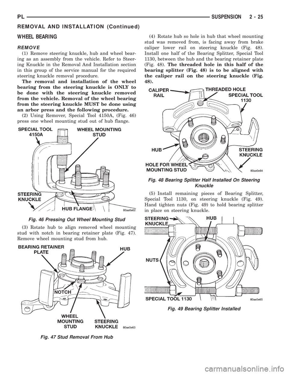
(2) Using Remover, Special Tool 4150A, (Fig. 46)
press one wheel mounting stud out of hub flange.
(3) Rotate hub to align removed wheel mounting
stud with notch in bearing retainer plate (Fig. 47).
Remove wheel mounting stud from hub.(4) Rotate hub so hole in hub that wheel mounting
stud was removed from, is facing away from brake
caliper lower rail on steering knuckle (Fig. 48).
Install one half of the Bearing Splitter, Special Tool
1130, between the hub and the bearing retainer plate
(Fig. 48).The threaded hole in this half of the
bearing splitter (Fig. 48) is to be aligned with
the caliper rail on the steering knuckle (Fig.
48).
(5) Install remaining pieces of Bearing Splitter,
Special Tool 1130, on steering knuckle (Fig. 49).
Hand tighten nuts (Fig. 49) to hold bearing splitter
in place on steering knuckle.
Fig. 46 Pressing Out Wheel Mounting Stud
Fig. 47 Stud Removal From Hub
Fig. 48 Bearing Splitter Half Installed On Steering
Knuckle
Fig. 49 Bearing Splitter Installed
PLSUSPENSION 2 - 25
REMOVAL AND INSTALLATION (Continued)
Page 37 of 1200
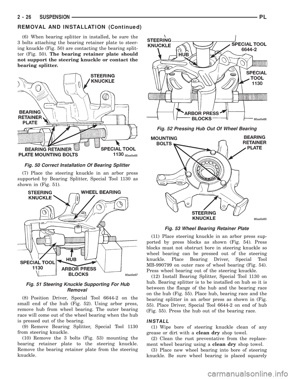
(6) When bearing splitter in installed, be sure the
3 bolts attaching the bearing retainer plate to steer-
ing knuckle (Fig. 50) are contacting the bearing split-
ter (Fig. 50).The bearing retainer plate should
not support the steering knuckle or contact the
bearing splitter.
(7) Place the steering knuckle in an arbor press
supported by Bearing Splitter, Special Tool 1130 as
shown in (Fig. 51).
(8) Position Driver, Special Tool 6644-2 on the
small end of the hub (Fig. 52). Using arbor press,
remove hub from wheel bearing. The outer bearing
race will come out of the wheel bearing when the hub
is pressed out of the bearing.
(9) Remove Bearing Splitter, Special Tool 1130
from steering knuckle.
(10) Remove the 3 bolts (Fig. 53) mounting the
bearing retainer plate to the steering knuckle.
Remove the bearing retainer plate from the steering
knuckle.(11) Place steering knuckle in an arbor press sup-
ported by press blocks as shown (Fig. 54). Press
blocks must not obstruct bore in steering knuckle so
wheel bearing can be pressed out of the steering
knuckle. Place Bearing Driver, Special Tool
MB-990799 on outer race of wheel bearing (Fig. 54).
Press wheel bearing out of the steering knuckle.
(12) Install Bearing Splitter, Special Tool 1130 on
hub. Bearing splitter is to be installed on hub so it is
between the flange of the hub and the bearing race
on the hub (Fig. 55). Place hub, bearing race and the
bearing splitter in an arbor press as shown in (Fig.
55). Place Driver, Special Tool 6644-2 on end of hub
(Fig. 55). Press the hub out of the bearing race.
INSTALL
(1) Wipe bore of steering knuckle clean of any
grease or dirt with aclean dryshop towel.
(2) Clean the rust preventative from the replace-
ment wheel bearing using aclean dryshop towel.
(3) Place new wheel bearing into bore of steering
knuckle. Be sure wheel bearing is placed squarely
Fig. 50 Correct Installation Of Bearing Splitter
Fig. 51 Steering Knuckle Supporting For Hub
Removal
Fig. 52 Pressing Hub Out Of Wheel Bearing
Fig. 53 Wheel Bearing Retainer Plate
2 - 26 SUSPENSIONPL
REMOVAL AND INSTALLATION (Continued)
Page 38 of 1200
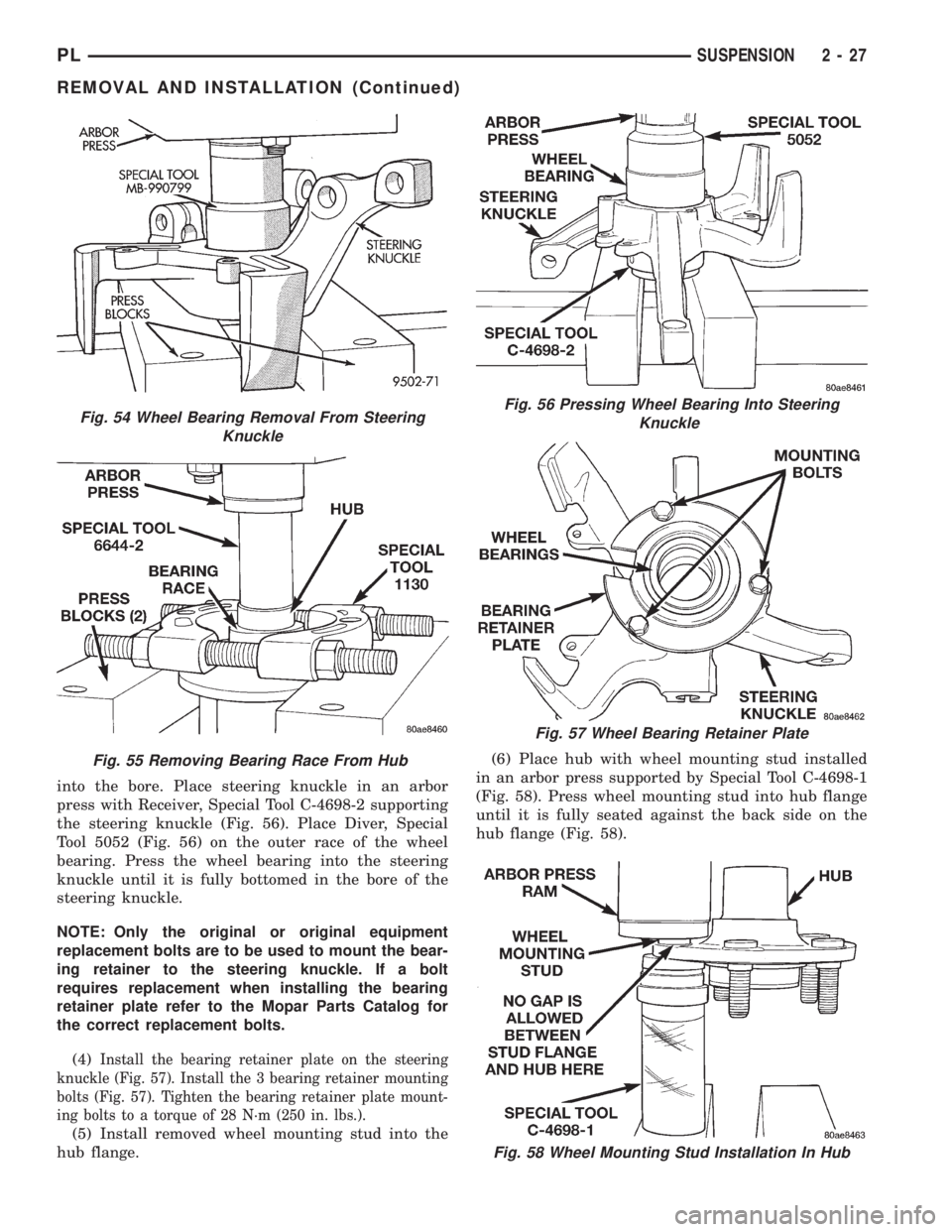
into the bore. Place steering knuckle in an arbor
press with Receiver, Special Tool C-4698-2 supporting
the steering knuckle (Fig. 56). Place Diver, Special
Tool 5052 (Fig. 56) on the outer race of the wheel
bearing. Press the wheel bearing into the steering
knuckle until it is fully bottomed in the bore of the
steering knuckle.
NOTE: Only the original or original equipment
replacement bolts are to be used to mount the bear-
ing retainer to the steering knuckle. If a bolt
requires replacement when installing the bearing
retainer plate refer to the Mopar Parts Catalog for
the correct replacement bolts.
(4)
Install the bearing retainer plate on the steering
knuckle (Fig. 57). Install the 3 bearing retainer mounting
bolts (Fig. 57). Tighten the bearing retainer plate mount-
ing bolts to a torque of 28 N´m (250 in. lbs.).
(5) Install removed wheel mounting stud into the
hub flange.(6) Place hub with wheel mounting stud installed
in an arbor press supported by Special Tool C-4698-1
(Fig. 58). Press wheel mounting stud into hub flange
until it is fully seated against the back side on the
hub flange (Fig. 58).
Fig. 58 Wheel Mounting Stud Installation In Hub
Fig. 54 Wheel Bearing Removal From Steering
Knuckle
Fig. 55 Removing Bearing Race From Hub
Fig. 56 Pressing Wheel Bearing Into Steering
Knuckle
Fig. 57 Wheel Bearing Retainer Plate
PLSUSPENSION 2 - 27
REMOVAL AND INSTALLATION (Continued)
Page 39 of 1200
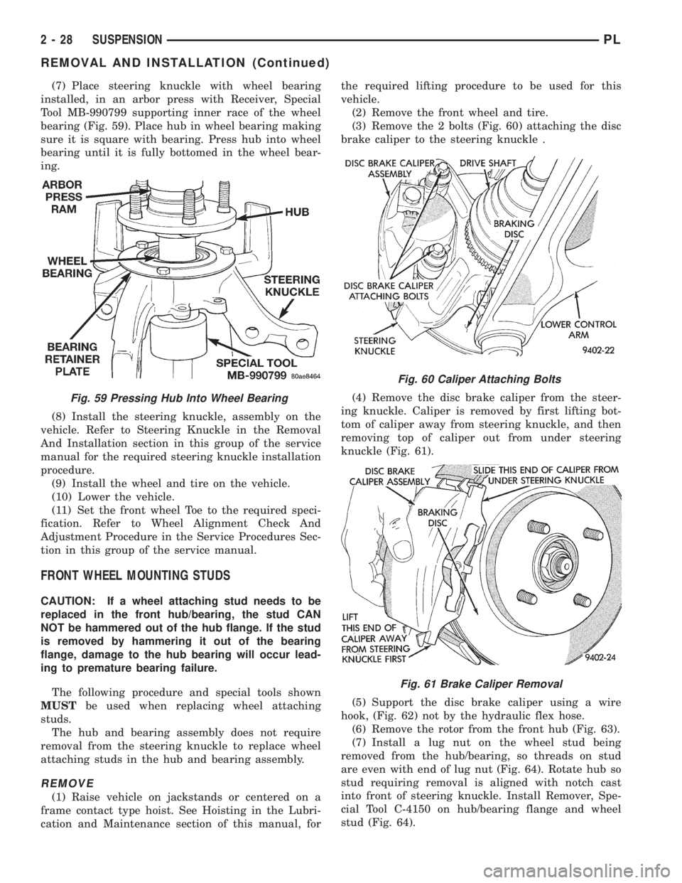
(7) Place steering knuckle with wheel bearing
installed, in an arbor press with Receiver, Special
Tool MB-990799 supporting inner race of the wheel
bearing (Fig. 59). Place hub in wheel bearing making
sure it is square with bearing. Press hub into wheel
bearing until it is fully bottomed in the wheel bear-
ing.
(8) Install the steering knuckle, assembly on the
vehicle. Refer to Steering Knuckle in the Removal
And Installation section in this group of the service
manual for the required steering knuckle installation
procedure.
(9) Install the wheel and tire on the vehicle.
(10) Lower the vehicle.
(11) Set the front wheel Toe to the required speci-
fication. Refer to Wheel Alignment Check And
Adjustment Procedure in the Service Procedures Sec-
tion in this group of the service manual.
FRONT WHEEL MOUNTING STUDS
CAUTION: If a wheel attaching stud needs to be
replaced in the front hub/bearing, the stud CAN
NOT be hammered out of the hub flange. If the stud
is removed by hammering it out of the bearing
flange, damage to the hub bearing will occur lead-
ing to premature bearing failure.
The following procedure and special tools shown
MUSTbe used when replacing wheel attaching
studs.
The hub and bearing assembly does not require
removal from the steering knuckle to replace wheel
attaching studs in the hub and bearing assembly.
REMOVE
(1) Raise vehicle on jackstands or centered on a
frame contact type hoist. See Hoisting in the Lubri-
cation and Maintenance section of this manual, forthe required lifting procedure to be used for this
vehicle.
(2) Remove the front wheel and tire.
(3) Remove the 2 bolts (Fig. 60) attaching the disc
brake caliper to the steering knuckle .
(4) Remove the disc brake caliper from the steer-
ing knuckle. Caliper is removed by first lifting bot-
tom of caliper away from steering knuckle, and then
removing top of caliper out from under steering
knuckle (Fig. 61).
(5) Support the disc brake caliper using a wire
hook, (Fig. 62) not by the hydraulic flex hose.
(6) Remove the rotor from the front hub (Fig. 63).
(7) Install a lug nut on the wheel stud being
removed from the hub/bearing, so threads on stud
are even with end of lug nut (Fig. 64). Rotate hub so
stud requiring removal is aligned with notch cast
into front of steering knuckle. Install Remover, Spe-
cial Tool C-4150 on hub/bearing flange and wheel
stud (Fig. 64).
Fig. 59 Pressing Hub Into Wheel Bearing
Fig. 60 Caliper Attaching Bolts
Fig. 61 Brake Caliper Removal
2 - 28 SUSPENSIONPL
REMOVAL AND INSTALLATION (Continued)
Page 40 of 1200
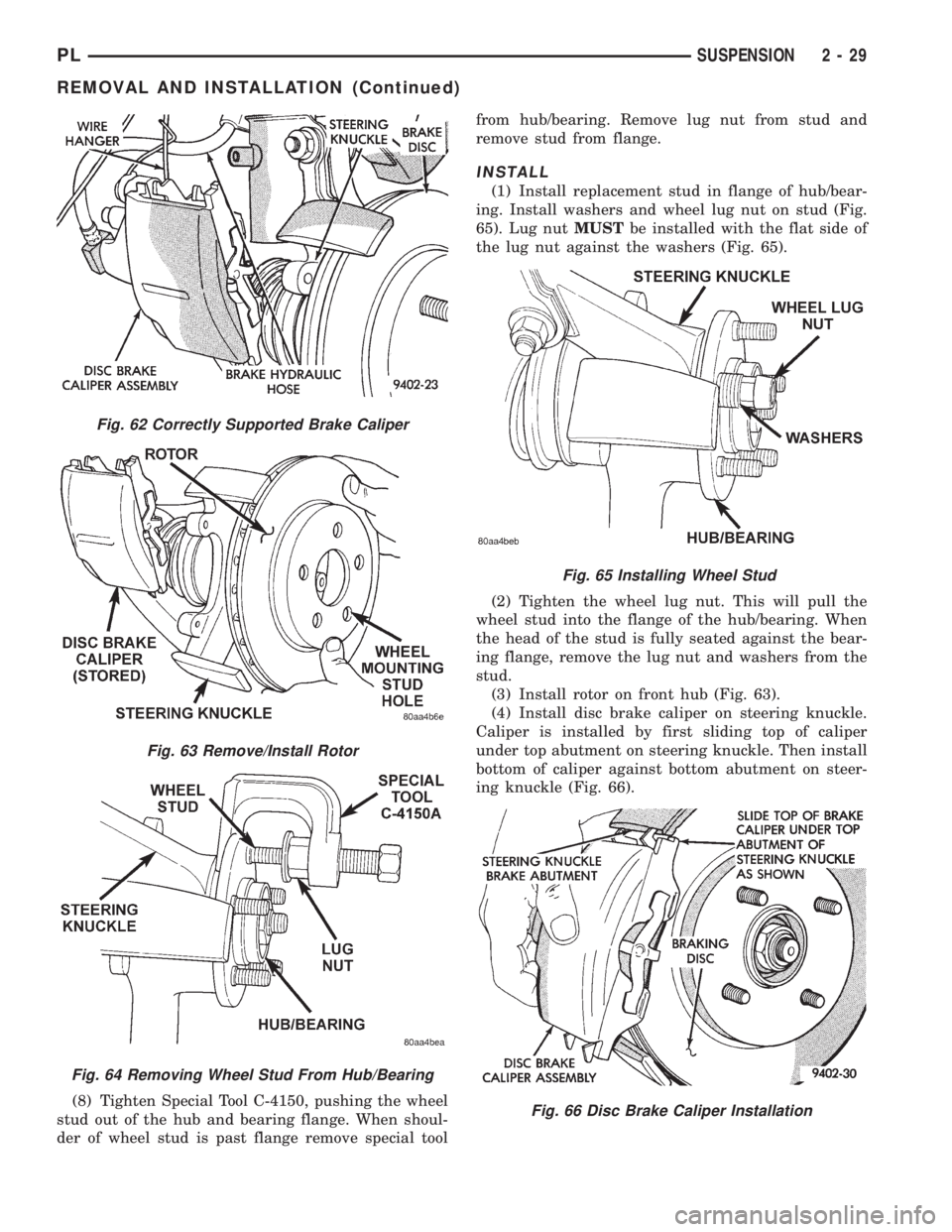
(8) Tighten Special Tool C-4150, pushing the wheel
stud out of the hub and bearing flange. When shoul-
der of wheel stud is past flange remove special toolfrom hub/bearing. Remove lug nut from stud and
remove stud from flange.
INSTALL
(1) Install replacement stud in flange of hub/bear-
ing. Install washers and wheel lug nut on stud (Fig.
65). Lug nutMUSTbe installed with the flat side of
the lug nut against the washers (Fig. 65).
(2) Tighten the wheel lug nut. This will pull the
wheel stud into the flange of the hub/bearing. When
the head of the stud is fully seated against the bear-
ing flange, remove the lug nut and washers from the
stud.
(3) Install rotor on front hub (Fig. 63).
(4) Install disc brake caliper on steering knuckle.
Caliper is installed by first sliding top of caliper
under top abutment on steering knuckle. Then install
bottom of caliper against bottom abutment on steer-
ing knuckle (Fig. 66).
Fig. 62 Correctly Supported Brake Caliper
Fig. 63 Remove/Install Rotor
Fig. 64 Removing Wheel Stud From Hub/Bearing
Fig. 65 Installing Wheel Stud
Fig. 66 Disc Brake Caliper Installation
PLSUSPENSION 2 - 29
REMOVAL AND INSTALLATION (Continued)