DODGE NEON 1999 Service Repair Manual
Manufacturer: DODGE, Model Year: 1999, Model line: NEON, Model: DODGE NEON 1999Pages: 1200, PDF Size: 35.29 MB
Page 1191 of 1200
DIGIT 5
Market Code
²C = Canada
²B = International
²M = Mexico
²U = United States
DIGIT 6
Open Space
DIGITS 7 THROUGH 23
Vehicle Identification Number²Refer to Vehicle Identification Number (VIN)
paragraph for proper breakdown of VIN code.
IF TWO BODY CODE PLATES ARE REQUIRED
The last code shown on either plate will be fol-
lowed by END. When two plates are required, the
last code space on the first plate will indicate (CTD)
When a second plate is required, the first four
spaces of each line will not be used due to overlap of
the plates.
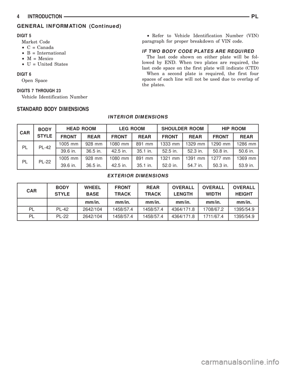
STANDARD BODY DIMENSIONS
INTERIOR DIMENSIONS
CARBODY
STYLEHEAD ROOM LEG ROOM SHOULDER ROOM HIP ROOM
FRONT REAR FRONT REAR FRONT REAR FRONT REAR
PL PL-421005 mm 928 mm 1080 mm 891 mm 1333 mm 1329 mm 1290 mm 1286 mm
39.6 in. 36.5 in. 42.5 in. 35.1 in. 52.5 in. 52.3 in. 50.8 in. 50.6 in.
PL PL-221005 mm 928 mm 1080 mm 891 mm 1321 mm 1391 mm 1277 mm 1369 mm
39.6 in. 36.5 in. 42.5 in. 35.1 in. 52.0 in. 54.7 in. 50.3 in. 53.9 in.
EXTERIOR DIMENSIONS
CARBODY
STYLEWHEEL
BASEFRONT
TRACKREAR
TRACKOVERALL
LENGTHOVERALL
WIDTHOVERALL
HEIGHT
mm/in. mm/in. mm/in. mm/in. mm/in. mm/in.
PL PL-42 2642/104 1458/57.4 1458/57.4 4364/171.8 1708/67.2 1395/54.9
PL PL-22 2642/104 1458/57.4 1458/57.4 4364/171.8 1711/67.4 1395/54.9
4 INTRODUCTIONPL
GENERAL INFORMATION (Continued)
Page 1192 of 1200
INTERNATIONAL VEHICLE CONTROL AND DISPLAY
SYMBOLS
INTERNATIONAL VEHICLE CONTROL AND
DISPLAY SYMBOLS
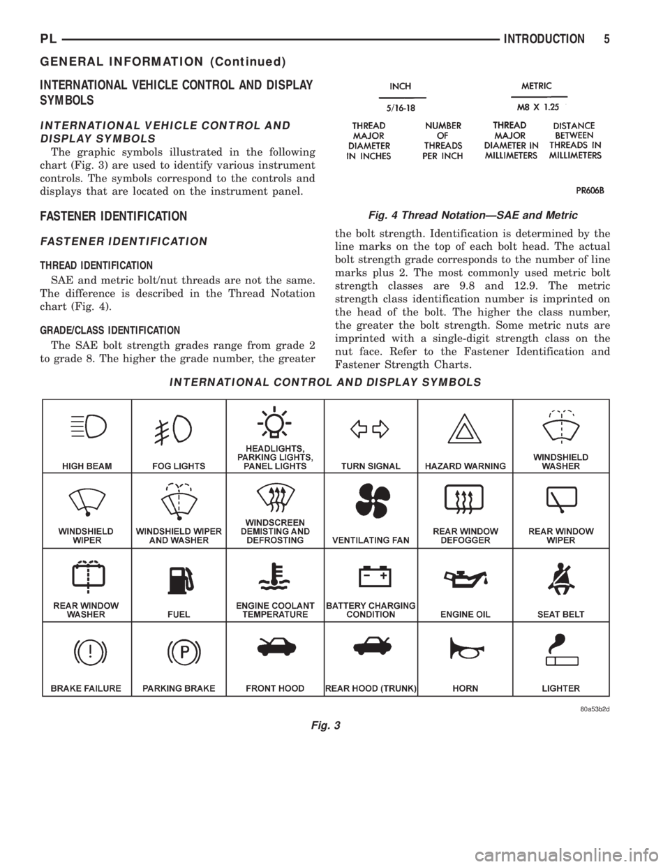
The graphic symbols illustrated in the following
chart (Fig. 3) are used to identify various instrument
controls. The symbols correspond to the controls and
displays that are located on the instrument panel.
FASTENER IDENTIFICATION
FASTENER IDENTIFICATION
THREAD IDENTIFICATION
SAE and metric bolt/nut threads are not the same.
The difference is described in the Thread Notation
chart (Fig. 4).
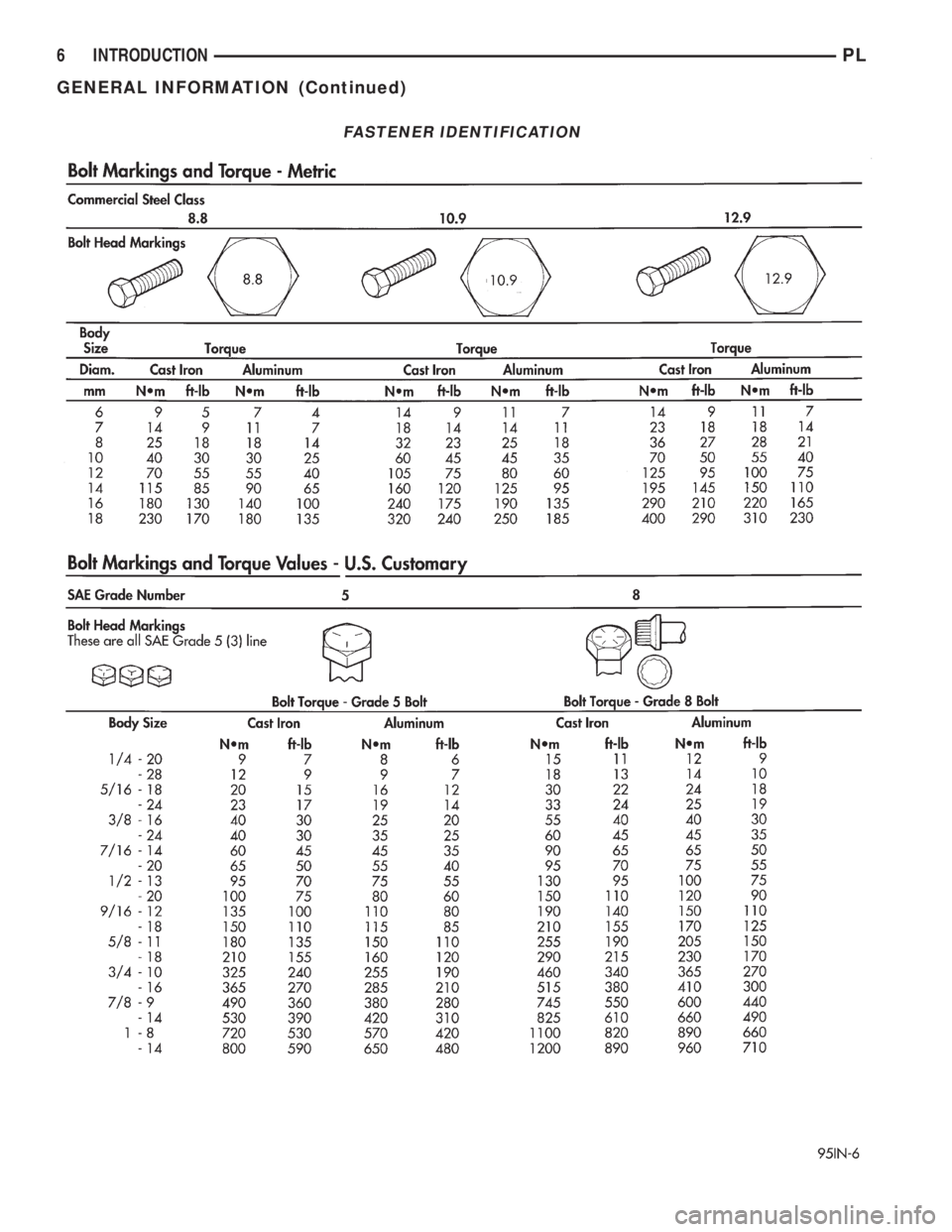
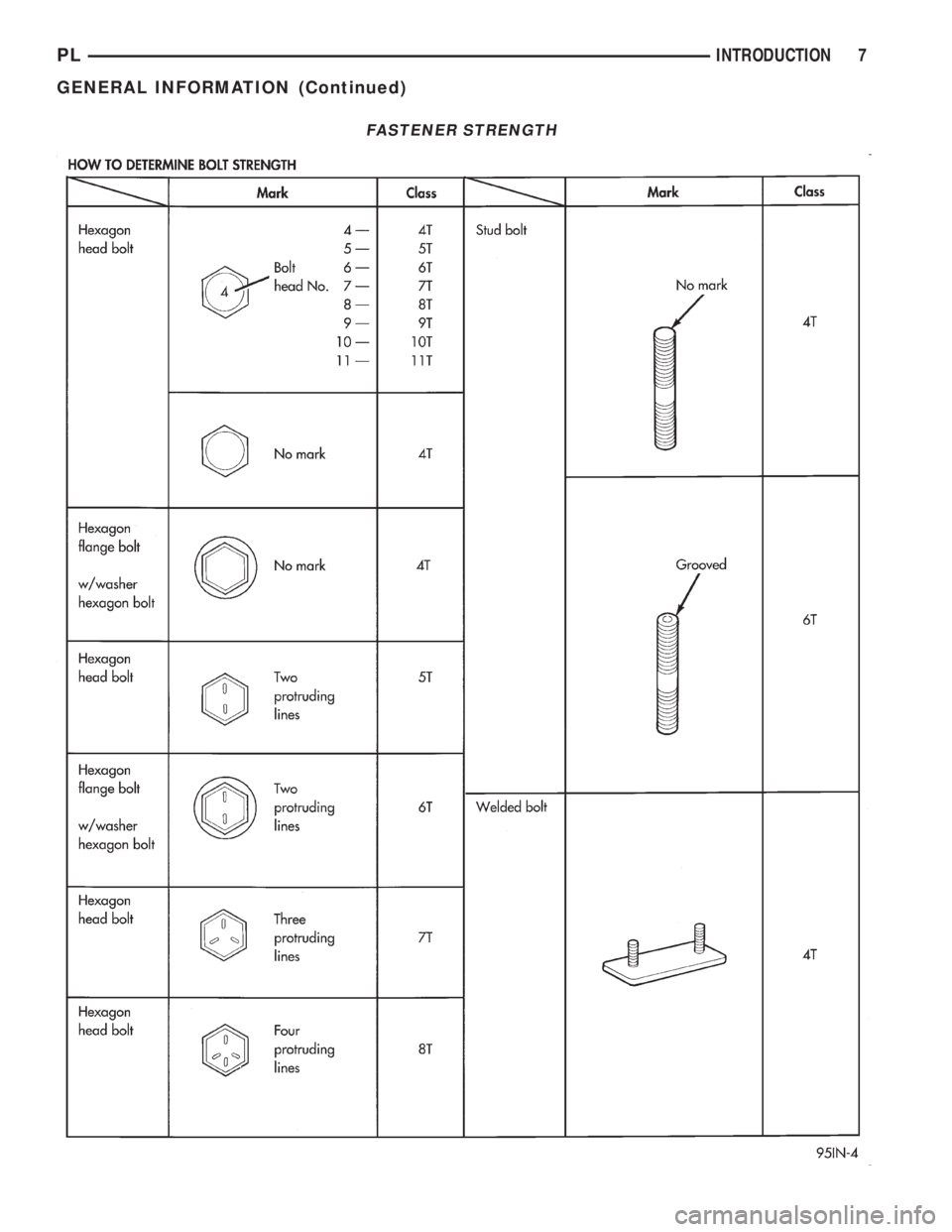
GRADE/CLASS IDENTIFICATION
The SAE bolt strength grades range from grade 2
to grade 8. The higher the grade number, the greaterthe bolt strength. Identification is determined by the
line marks on the top of each bolt head. The actual
bolt strength grade corresponds to the number of line
marks plus 2. The most commonly used metric bolt
strength classes are 9.8 and 12.9. The metric
strength class identification number is imprinted on
the head of the bolt. The higher the class number,
the greater the bolt strength. Some metric nuts are
imprinted with a single-digit strength class on the
nut face. Refer to the Fastener Identification and
Fastener Strength Charts.
INTERNATIONAL CONTROL AND DISPLAY SYMBOLS
Fig. 3
Fig. 4 Thread NotationÐSAE and Metric
PLINTRODUCTION 5
GENERAL INFORMATION (Continued)
Page 1193 of 1200
FASTENER IDENTIFICATION
6 INTRODUCTIONPL
GENERAL INFORMATION (Continued)
Page 1194 of 1200
FASTENER STRENGTH
PLINTRODUCTION 7
GENERAL INFORMATION (Continued)
Page 1195 of 1200
METRIC SYSTEM
WARNING: USE OF AN INCORRECT FASTENER
MAY RESULT IN COMPONENT DAMAGE OR PER-
SONAL INJURY.
Figure art, specifications and torque references in
this Service Manual are identified in metric and SAE
format.
During any maintenance or repair procedures, it is
important to salvage metric fasteners (nuts, bolts,
etc.) for reassembly. If the fastener is not salvage-
able, a fastener of equivalent specification should be
used.
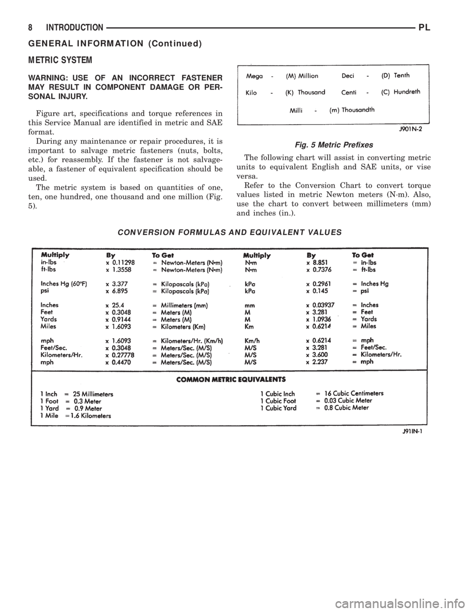
The metric system is based on quantities of one,
ten, one hundred, one thousand and one million (Fig.
5).The following chart will assist in converting metric
units to equivalent English and SAE units, or vise
versa.
Refer to the Conversion Chart to convert torque
values listed in metric Newton meters (N´m). Also,
use the chart to convert between millimeters (mm)
and inches (in.).
CONVERSION FORMULAS AND EQUIVALENT VALUES
Fig. 5 Metric Prefixes
8 INTRODUCTIONPL
GENERAL INFORMATION (Continued)
Page 1196 of 1200
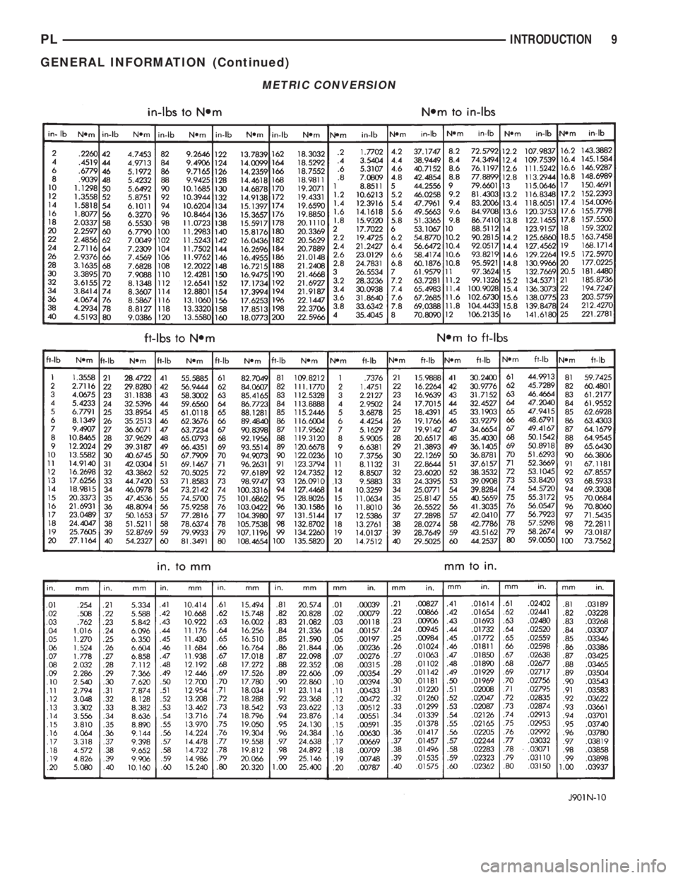
METRIC CONVERSION
PLINTRODUCTION 9
GENERAL INFORMATION (Continued)
Page 1197 of 1200
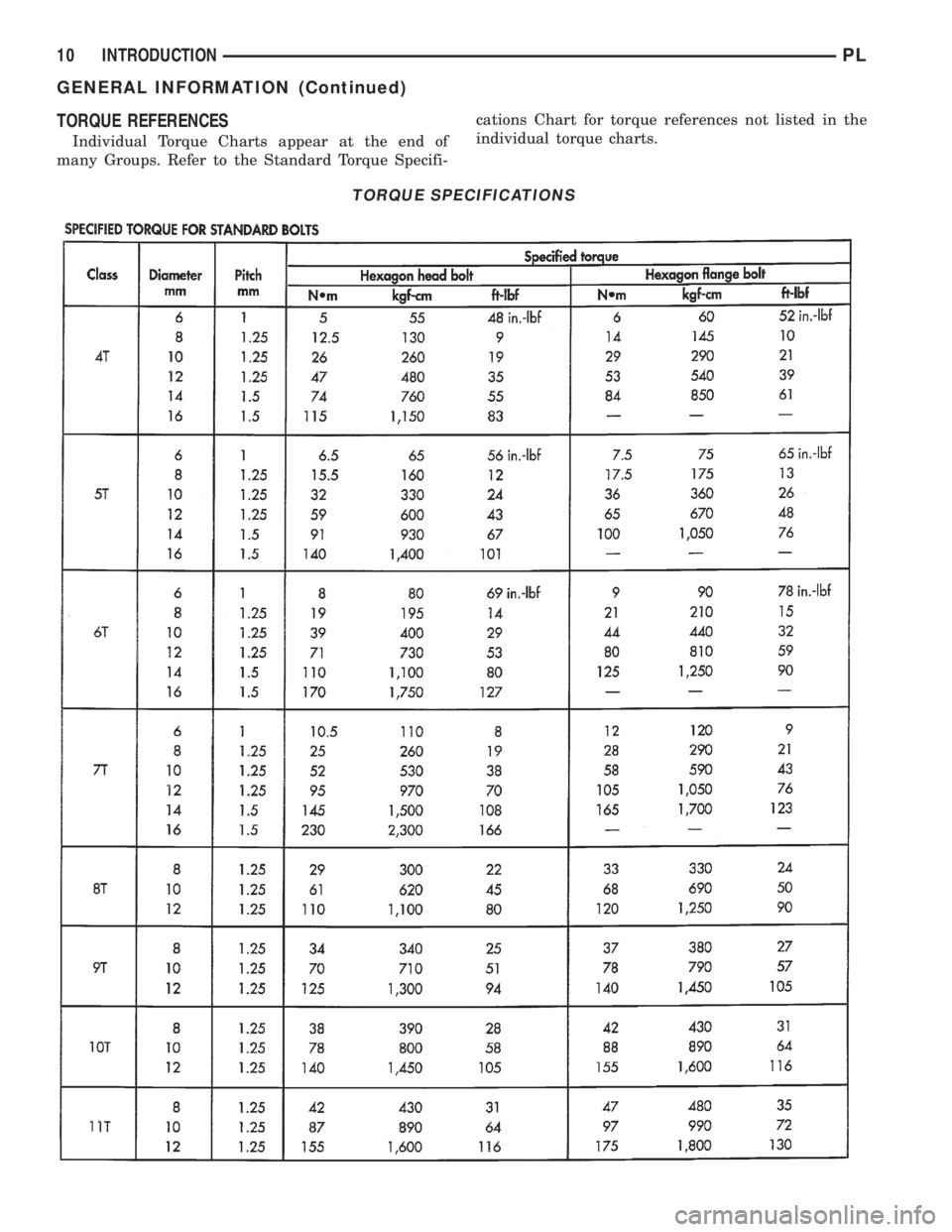
TORQUE REFERENCES
Individual Torque Charts appear at the end of
many Groups. Refer to the Standard Torque Specifi-cations Chart for torque references not listed in the
individual torque charts.
TORQUE SPECIFICATIONS
10 INTRODUCTIONPL
GENERAL INFORMATION (Continued)
Page 1198 of 1200
INTRODUCTION
CONTENTS
page page
GENERAL INFORMATION
E-MARK LABEL......................... 2MANUFACTURER PLATE.................. 2
VEHICLE IDENTIFICATION NUMBER......... 1
GENERAL INFORMATION
VEHICLE IDENTIFICATION NUMBER
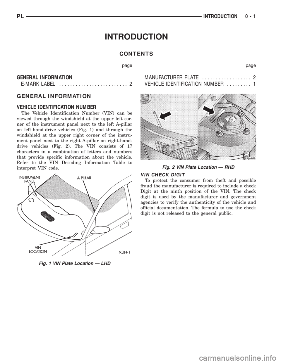
The Vehicle Identification Number (VIN) can be
viewed through the windshield at the upper left cor-
ner of the instrument panel next to the left A-pillar
on left-hand-drive vehicles (Fig. 1) and through the
windshield at the upper right corner of the instru-
ment panel next to the right A-pillar on right-hand-
drive vehicles (Fig. 2). The VIN consists of 17
characters in a combination of letters and numbers
that provide specific information about the vehicle.
Refer to the VIN Decoding Information Table to
interpret VIN code.
VIN CHECK DIGIT
To protect the consumer from theft and possible
fraud the manufacturer is required to include a check
Digit at the ninth position of the VIN. The check
digit is used by the manufacturer and government
agencies to verify the authenticity of the vehicle and
official documentation. The formula to use the check
digit is not released to the general public.
Fig. 1 VIN Plate Location Ð LHD
Fig. 2 VIN Plate Location Ð RHD
PLINTRODUCTION 0 - 1
Page 1199 of 1200
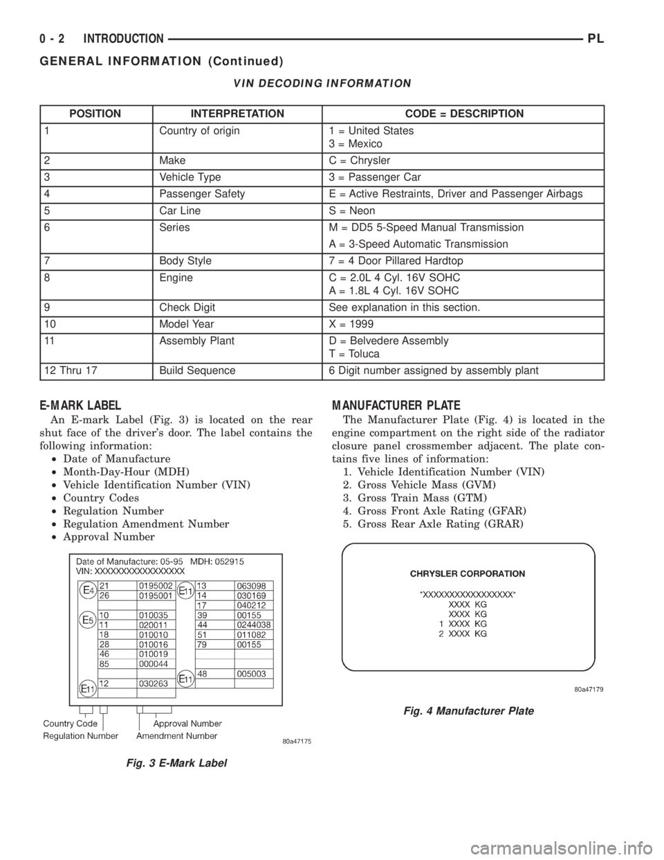
VIN DECODING INFORMATION
POSITION INTERPRETATION CODE = DESCRIPTION
1 Country of origin 1 = United States
3 = Mexico
2 Make C = Chrysler
3 Vehicle Type 3 = Passenger Car
4 Passenger Safety E = Active Restraints, Driver and Passenger Airbags
5 Car Line S = Neon
6 Series M = DD5 5-Speed Manual Transmission
A = 3-Speed Automatic Transmission
7 Body Style7 = 4 Door Pillared Hardtop
8 Engine C = 2.0L 4 Cyl. 16V SOHC
A = 1.8L 4 Cyl. 16V SOHC
9 Check Digit See explanation in this section.
10 Model Year X = 1999
11 Assembly Plant D = Belvedere Assembly
T = Toluca
12 Thru 17 Build Sequence 6 Digit number assigned by assembly plant
E-MARK LABEL
An E-mark Label (Fig. 3) is located on the rear
shut face of the driver's door. The label contains the
following information:
²Date of Manufacture
²Month-Day-Hour (MDH)
²Vehicle Identification Number (VIN)
²Country Codes
²Regulation Number
²Regulation Amendment Number
²Approval Number
MANUFACTURER PLATE
The Manufacturer Plate (Fig. 4) is located in the
engine compartment on the right side of the radiator
closure panel crossmember adjacent. The plate con-
tains five lines of information:
1. Vehicle Identification Number (VIN)
2. Gross Vehicle Mass (GVM)
3. Gross Train Mass (GTM)
4. Gross Front Axle Rating (GFAR)
5. Gross Rear Axle Rating (GRAR)
Fig. 3 E-Mark Label
Fig. 4 Manufacturer Plate
0 - 2 INTRODUCTIONPL
GENERAL INFORMATION (Continued)
Page 1200 of 1200
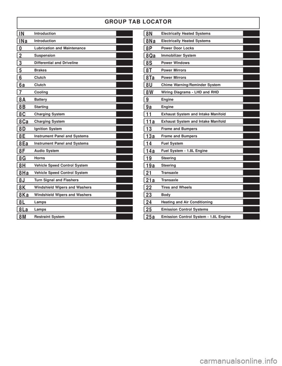
GROUP TAB LOCATOR
INIntroduction
INaIntroduction
0Lubrication and Maintenance
2Suspension
3Differential and Driveline
5Brakes
6Clutch
6aClutch
7Cooling
8ABattery
8BStarting
8CCharging System
8CaCharging System
8DIgnition System
8EInstrument Panel and Systems
8EaInstrument Panel and Systems
8FAudio System
8GHorns
8HVehicle Speed Control System
8HaVehicle Speed Control System
8JTurn Signal and Flashers
8KWindshield Wipers and Washers
8KaWindshield Wipers and Washers
8LLamps
8LaLamps
8MRestraint System
8NElectrically Heated Systems
8NaElectrically Heated Systems
8PPower Door Locks
8QaImmobilizer System
8SPower Windows
8TPower Mirrors
8TaPower Mirrors
8UChime Warning/Reminder System
8WWiring Diagrams - LHD and RHD
9Engine
9aEngine
11Exhaust System and Intake Manifold
11aExhaust System and Intake Manifold
13Frame and Bumpers
13aFrame and Bumpers
14Fuel System
14aFuel System - 1.8L Engine
19Steering
19aSteering
21Transaxle
21aTransaxle
22Tires and Wheels
23Body
24Heating and Air Conditioning
25Emission Control Systems
25aEmission Control System - 1.8L Engine