DODGE NEON 1999 Service Manual PDF
Manufacturer: DODGE, Model Year: 1999, Model line: NEON, Model: DODGE NEON 1999Pages: 1200, PDF Size: 35.29 MB
Page 61 of 1200
link mounting bolt at crossmember MUST be
installed, with head of bolt facing rear of vehi-
cle. The long attaching bolt must be used at
rear crossmember and short bolt used at
knuckle.
(1) Install washer on short lateral link attaching
bolt. Then install short lateral link attaching bolt,
into lateral link having the same size bushing
sleeves. Then install lateral link, bolt and washer
onto knuckle as an assembly, with head of bolt facing
to front of vehicle (Fig. 24).
(2) Install lateral link with small and large bush-
ing sleeve, on lateral link attaching bolt in rear
knuckle (Fig. 24).Small bushing sleeve must be
installed on bolt in rear knuckle with large
bushing sleeve at crossmember of vehicle.
(3) Install washer and nut onto lateral link attach-
ing bolt at rear knuckle (Fig. 24).Do not tighten
the lateral link to rear knuckle attaching bolt
at this time.
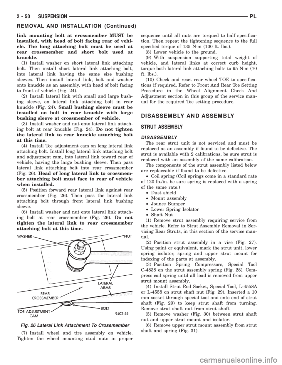
(4) Install Toe adjustment cam on long lateral link
attaching bolt. Install long lateral link attaching bolt
and adjustment cam, into lateral link toward rear of
vehicle, having the large bushing sleeve. Then pass
lateral link attaching bolt into rear crossmember
(Fig. 26).Head of long lateral link to crossmem-
ber attaching bolt must face to rear of vehicle
when installed.
(5) Position forward rear lateral link against rear
crossmember (Fig. 26). Then pass the lateral link
attaching bolt through front lateral link bushing
sleeve.
(6) Install washer and nut onto lateral link attach-
ing bolt at rear crossmember (Fig. 26).Do not
tighten the lateral link to rear crossmember
attaching bolt at this time.
(7) Install wheel and tire assembly on vehicle.
Tighten the wheel mounting stud nuts in propersequence until all nuts are torqued to half specifica-
tion. Then repeat the tightening sequence to the full
specified torque of 135 N´m (100 ft. lbs.).
(8) Lower vehicle to the ground.
(9) With suspension supporting total weight of
vehicle, and lateral links at correct curb height,
torque both lateral link attaching bolts to 95 N´m (70
ft. lbs.).
(10) Check and reset rear wheel TOE to specifica-
tions if required. Refer to Front And Rear Toe Setting
Procedure in the Wheel Alignment Check And
Adjustment section in this group of the service man-
ual for the required Toe setting procedure.
DISASSEMBLY AND ASSEMBLY
STRUT ASSEMBLY
DISASSEMBLY
The rear strut unit is not serviced and must be
replaced as an assembly if found to be defective. The
strut is available with 2 calibrations, be sure strut is
replaced with an assembly of the same calibration.
The components of the strut assembly listed below
are replaceable if found to be defective.
²Coil spring (Coil springs come in a standard rate
of 120 lb./in. be sure spring is replaced with a spring
of the same rate.)
²Dust shield
²Mount assembly
²Jounce Bumper
²Lower Spring Isolator
²Shaft Nut
(1) Remove strut assembly requiring service from
the vehicle. Refer to Strut Assembly Removal in Ser-
vicing Rear Struts, in this section of the service man-
ual.
(2) Position strut assembly in a vise (Fig. 27).
Using paint or equivalent, mark the strut unit, lower
spring isolator, spring and upper strut mount for
indexing of the parts at assembly.
(3) Position Spring Compressors, Special Tool
C-4838 on the strut assembly spring (Fig. 28). Com-
press coil spring until all load is removed from upper
strut mount assembly.
(4) Install Strut Rod Socket, Special Tool, L-4558A
or L-4558 on strut shaft nut (Fig. 29). Inserted a 10
mm socket through special tool and onto end of strut
shaft (Fig. 29) to keep strut shaft from turning.
Remove strut shaft nut from strut shaft.
(5) Remove washer (Fig. 30) between strut shaft
nut and upper strut mount and isolator.
(6) Remove upper strut mount assembly from strut
shaft and spring (Fig. 31).
Fig. 26 Lateral Link Attachment To Crossmember
2 - 50 SUSPENSIONPL
REMOVAL AND INSTALLATION (Continued)
Page 62 of 1200
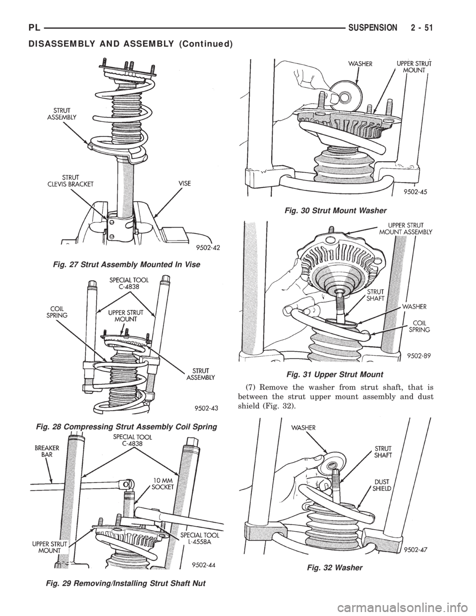
(7) Remove the washer from strut shaft, that is
between the strut upper mount assembly and dust
shield (Fig. 32).
Fig. 27 Strut Assembly Mounted In Vise
Fig. 28 Compressing Strut Assembly Coil Spring
Fig. 29 Removing/Installing Strut Shaft Nut
Fig. 30 Strut Mount Washer
Fig. 31 Upper Strut Mount
Fig. 32 Washer
PLSUSPENSION 2 - 51
DISASSEMBLY AND ASSEMBLY (Continued)
Page 63 of 1200
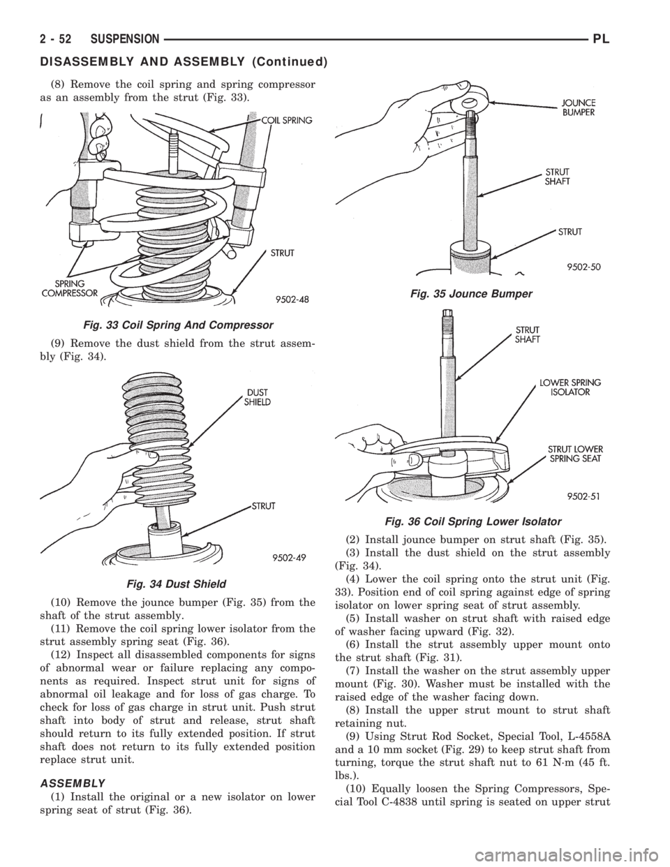
(8) Remove the coil spring and spring compressor
as an assembly from the strut (Fig. 33).
(9) Remove the dust shield from the strut assem-
bly (Fig. 34).
(10) Remove the jounce bumper (Fig. 35) from the
shaft of the strut assembly.
(11) Remove the coil spring lower isolator from the
strut assembly spring seat (Fig. 36).
(12) Inspect all disassembled components for signs
of abnormal wear or failure replacing any compo-
nents as required. Inspect strut unit for signs of
abnormal oil leakage and for loss of gas charge. To
check for loss of gas charge in strut unit. Push strut
shaft into body of strut and release, strut shaft
should return to its fully extended position. If strut
shaft does not return to its fully extended position
replace strut unit.
ASSEMBLY
(1) Install the original or a new isolator on lower
spring seat of strut (Fig. 36).(2) Install jounce bumper on strut shaft (Fig. 35).
(3) Install the dust shield on the strut assembly
(Fig. 34).
(4) Lower the coil spring onto the strut unit (Fig.
33). Position end of coil spring against edge of spring
isolator on lower spring seat of strut assembly.
(5) Install washer on strut shaft with raised edge
of washer facing upward (Fig. 32).
(6) Install the strut assembly upper mount onto
the strut shaft (Fig. 31).
(7) Install the washer on the strut assembly upper
mount (Fig. 30). Washer must be installed with the
raised edge of the washer facing down.
(8) Install the upper strut mount to strut shaft
retaining nut.
(9) Using Strut Rod Socket, Special Tool, L-4558A
and a 10 mm socket (Fig. 29) to keep strut shaft from
turning, torque the strut shaft nut to 61 N´m (45 ft.
lbs.).
(10) Equally loosen the Spring Compressors, Spe-
cial Tool C-4838 until spring is seated on upper strut
Fig. 33 Coil Spring And Compressor
Fig. 34 Dust Shield
Fig. 35 Jounce Bumper
Fig. 36 Coil Spring Lower Isolator
2 - 52 SUSPENSIONPL
DISASSEMBLY AND ASSEMBLY (Continued)
Page 64 of 1200
mount and all tension is relieved from the spring
compressors.
(11) Install the strut assembly back into the vehi-
cle. Refer to Strut Assembly Removal in Servicing
Rear Struts in this section of the service manual.
(12) Check and reset rear wheel TOE to specifica-
tions if required.
STABILIZER BAR BUSHINGS
(1) If stabilizer bar to frame rail bushings require
replacement at time of inspection, install new bush-
ings before installing stabilizer bar. Bushings are
replaced by opening slit on bushings and peeling
them off stabilizer bar. Install new bushings on sta-
bilizer bar, by spreading bushing at slit and forcing
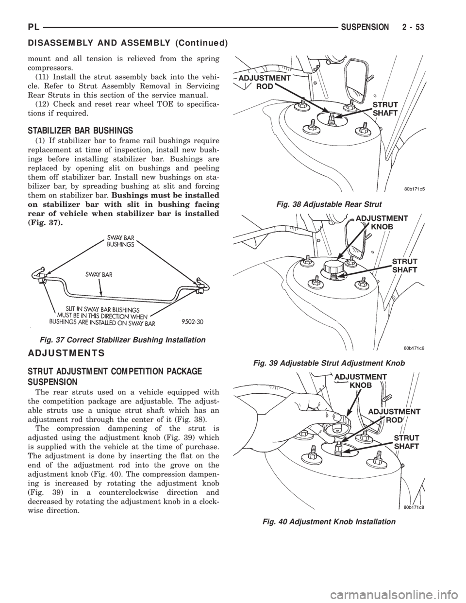
them on stabilizer bar.Bushings must be installed
on stabilizer bar with slit in bushing facing
rear of vehicle when stabilizer bar is installed
(Fig. 37).
ADJUSTMENTS
STRUT ADJUSTMENT COMPETITION PACKAGE
SUSPENSION
The rear struts used on a vehicle equipped with
the competition package are adjustable. The adjust-
able struts use a unique strut shaft which has an
adjustment rod through the center of it (Fig. 38).
The compression dampening of the strut is
adjusted using the adjustment knob (Fig. 39) which
is supplied with the vehicle at the time of purchase.
The adjustment is done by inserting the flat on the
end of the adjustment rod into the grove on the
adjustment knob (Fig. 40). The compression dampen-
ing is increased by rotating the adjustment knob
(Fig. 39) in a counterclockwise direction and
decreased by rotating the adjustment knob in a clock-
wise direction.
Fig. 37 Correct Stabilizer Bushing Installation
Fig. 38 Adjustable Rear Strut
Fig. 39 Adjustable Strut Adjustment Knob
Fig. 40 Adjustment Knob Installation
PLSUSPENSION 2 - 53
DISASSEMBLY AND ASSEMBLY (Continued)
Page 65 of 1200
SPECIFICATIONS
REAR SUSPENSION FASTENER TORQUE
SPECIFICATIONS
DESCRIPTION TORQUE
STRUT ASSEMBLY:
To Body Attaching Nuts.......34N´m(300 in. lbs.)
Clevis Bracket To Knuckle
Nut/Bolt..................95N´m(70ft.lbs.)
Strut Assembly Shaft Nut.......75N´m(55ft.lbs.)
BRAKE SUPPORT PLATE:
To Knuckle Bolts..............68N´m(50ft.lbs.)
STABILIZER BAR:
Bushing Retainer To
Frame Bolt...............34N´m(300 in. lbs.)
To Strut Attaching Link Nut . . .34 N´m (300 in. lbs.)
TENSION STRUT:
Shaft Nut...................95N´m(70ft.lbs.)
Bracket To Body Attaching
Bolts.....................95N´m(70ft.lbs.)
LATERAL LINK:
Attaching Nut................95N´m(70ft.lbs.)
DISC BRAKE CALIPER:
To Adapter Mounting Bolt......22N´m(16ft.lbs.)
Brake Hose To Caliper
Mounting Bolt..............45N´m(35ft.lbs.)
Adapter To Knuckle
Mounting Bolt..............68N´m(50ft.lbs.)
BRAKE HOSE:
Bracket Mounting Bolt........23N´m(17ft.lbs.)
HUB AND BEARING:
To Knuckle Retaining Nut.....216 N´m (160 ft. lbs.)
Wheel Stud Lug Nuts
(All Wheel Types). . . .109-150 N´m (80-110 ft. lbs.)
SPECIAL TOOLS
REAR SUSPENSION
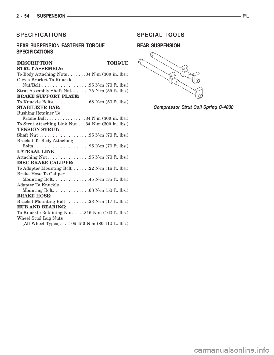
Compressor Strut Coil Spring C-4838
2 - 54 SUSPENSIONPL
Page 66 of 1200
DIFFERENTIAL AND DRIVELINE
CONTENTS
page page
GENERAL INFORMATION
FRONT DRIVESHAFTS.................... 1
DIAGNOSIS AND TESTING
DRIVESHAFT DIAGNOSIS.................. 2
REMOVAL AND INSTALLATION
FRONT DRIVESHAFTS.................... 2
DISASSEMBLY AND ASSEMBLY
DRIVESHAFT RECONDITION............... 7INNER TRIPOD JOINT SEAL BOOT.......... 9
OUTER C/V JOINT SEAL BOOT............ 13
SPECIFICATIONS
TORQUE.............................. 16
SPECIAL TOOLS
DRIVESHAFT........................... 16
GENERAL INFORMATION
FRONT DRIVESHAFTS
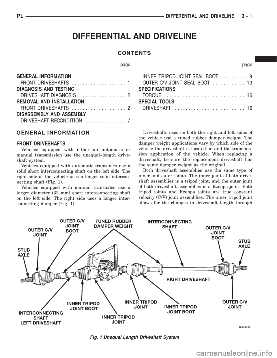
Vehicles equipped with either an automatic or
manual transmission use the unequal±length drive-
shaft system.
Vehicles equipped with automatic transaxles use a
solid short interconnecting shaft on the left side. The
right side of the vehicle uses a longer solid intercon-
necting shaft (Fig. 1).
Vehicles equipped with manual transaxles use a
larger diameter (32 mm) short interconnecting shaft
on the left side. The right side uses a longer inter-
connecting damper (Fig. 1).Driveshafts used on both the right and left sides of
the vehicle use a tuned rubber damper weight. The
damper weight applications vary by which side of the
vehicle the driveshaft is located on and the transmis-
sion application of the vehicle. When replacing a
driveshaft, be sure the replacement driveshaft has
the same damper weight as the original.
Both driveshaft assemblies use the same type of
inner and outer joints. The inner joint of both drive-
shaft assemblies is a tripod joint, and the outer joint
of both driveshaft assemblies is a Rzeppa joint. Both
tripod joints and Rzeppa joints are true constant
velocity (C/V) joint assemblies. The inner tripod joint
allows for the changes in driveshaft length through
Fig. 1 Unequal Length Driveshaft System
PLDIFFERENTIAL AND DRIVELINE 3 - 1
Page 67 of 1200
the jounce and rebound travel of the front suspen-
sion.
On vehicles equipped with ABS brakes, the outer
C/V joint is equipped with a tone wheel used to
determine vehicle speed for ABS brake operation.
The inner tripod joint of both driveshafts is splined
into the transaxle side gears. The inner tripod joints
are retained in the side gears of the transaxle using
a snap ring located in the stub shaft of the tripod
joint. The outer C/V joint has a stub shaft that is
splined into the wheel hub and retained by a hub nut
using a nut lock and cotter pin.
NOTE: This vehicle does not use a rubber±lip bear-
ing seal as on previous front±wheel±drive cars to
prevent contamination of the front wheel bearing.
On these vehicles, the face of the outer C/V joint
fits deeply into the steering knuckle, using a close
outer C/V joint±to±steering knuckle fit. This design
deters direct water splash on bearing seal while
allowing any water that gets in, to run out the bot-
tom of the steering knuckle bearing bore. It is
important to thoroughly clean the outer C/V joint
and the wheel bearing area in the steering knuckle
before it is assembled after servicing.
DIAGNOSIS AND TESTING
DRIVESHAFT DIAGNOSIS
VEHICLE INSPECTION
(1) Check for grease in the vicinity of the inboard
tripod joint and outboard C/V joint; this is a sign of
inner or outer joint seal boot or seal boot clamp dam-
age.
(2) A light film of grease may appear on the right
inner tripod joint seal boot; this is considered normal
and should not require replacement of the seal boot.
The right inner tripod joint seal boot is made of sili-
cone rubber; which will allow the weeping (sweating)
of the joint lubricant to pass through it while in oper-
ation.
NOISE AND/OR VIBRATION IN TURNS
A clicking noise and/or a vibration in turns could
be caused by one of the following conditions.
(1) Damaged outer C/V or inner tripod joint seal
boot or seal boot clamps. This will result in the loss
and/or contamination of the joint grease, resulting in
inadequate lubrication of the joint.
(2) Noise may also be caused by another compo-
nent of the vehicle coming in contact with the drive-
shafts.
CLUNKING NOISE DURING ACCELERATION
This noise may be a result of one of the following
conditions:
(1) A torn seal boot on the inner or outer joint of
the driveshaft assembly.
(2) A loose or missing clamp on the inner or outer
joint of the driveshaft assembly.
(3) A damaged or worn driveshaft C/V joint.
SHUDDER OR VIBRATION DURING
ACCELERATION
(1) A worn or damaged driveshaft inner tripod
joint.
(2) A sticking tripod joint spider assembly (inner
tripod joint only).
(3) Improper wheel alignment. See Wheel Align-
ment in this group for alignment checking and set-
ting procedures and specifications.
VIBRATION AT HIGHWAY SPEEDS
(1) Foreign material (mud, etc.) packed on the
backside of the wheel(s).
(2) Out of balance front tires or wheels. See Group
22, Wheels And Tires for the required balancing pro-
cedure.
(3) Improper tire and/or wheel runout. See Group
22, Wheels And Tires for the required runout check-
ing procedure.
REMOVAL AND INSTALLATION
FRONT DRIVESHAFTS
CAUTION: Boot sealing is vital to retain special
lubricants and to prevent foreign contaminants
from entering the C/V joint. Mishandling, such as
allowing the assemblies to dangle unsupported, or
pulling or pushing the ends can cut boots or dam-
age C/V joints. During removal and installation pro-
cedures, always support both ends of the driveshaft
to prevent damage.
REMOVAL
CAUTION: The driveshaft, when installed, acts as a
bolt and secures the front hub/bearing assembly. If
vehicle is to be supported or moved on its wheels
with a driveshaft removed, install a PROPER±SIZED
BOLT AND NUT through front hub. Tighten bolt and
nut to 203 N´m (150 ft. lbs.). This will ensure that
the hub bearing cannot loosen.
(1) Remove cotter pin, nut lock, and spring washer
(Fig. 2) from the end of the outer C/V joint stub axle.
(2) Loosen (but do not remove) stub axle±to±hub/
bearing retaining nut (Fig. 3). Loosen hub nut while
3 - 2 DIFFERENTIAL AND DRIVELINEPL
GENERAL INFORMATION (Continued)
Page 68 of 1200
vehicle is on the floor with the brakes applied. The
front hub and driveshaft are splined together and
retained by the hub nut.
(3) Raise vehicle on jack stands or centered on a
frame contact±type hoist. See Hoisting in the Lubri-
cation and Maintenance section for required lifting
procedure to be used for this vehicle.
(4) Remove front tire and wheel assembly from the
hub.
(5) Remove front disc brake caliper assembly to
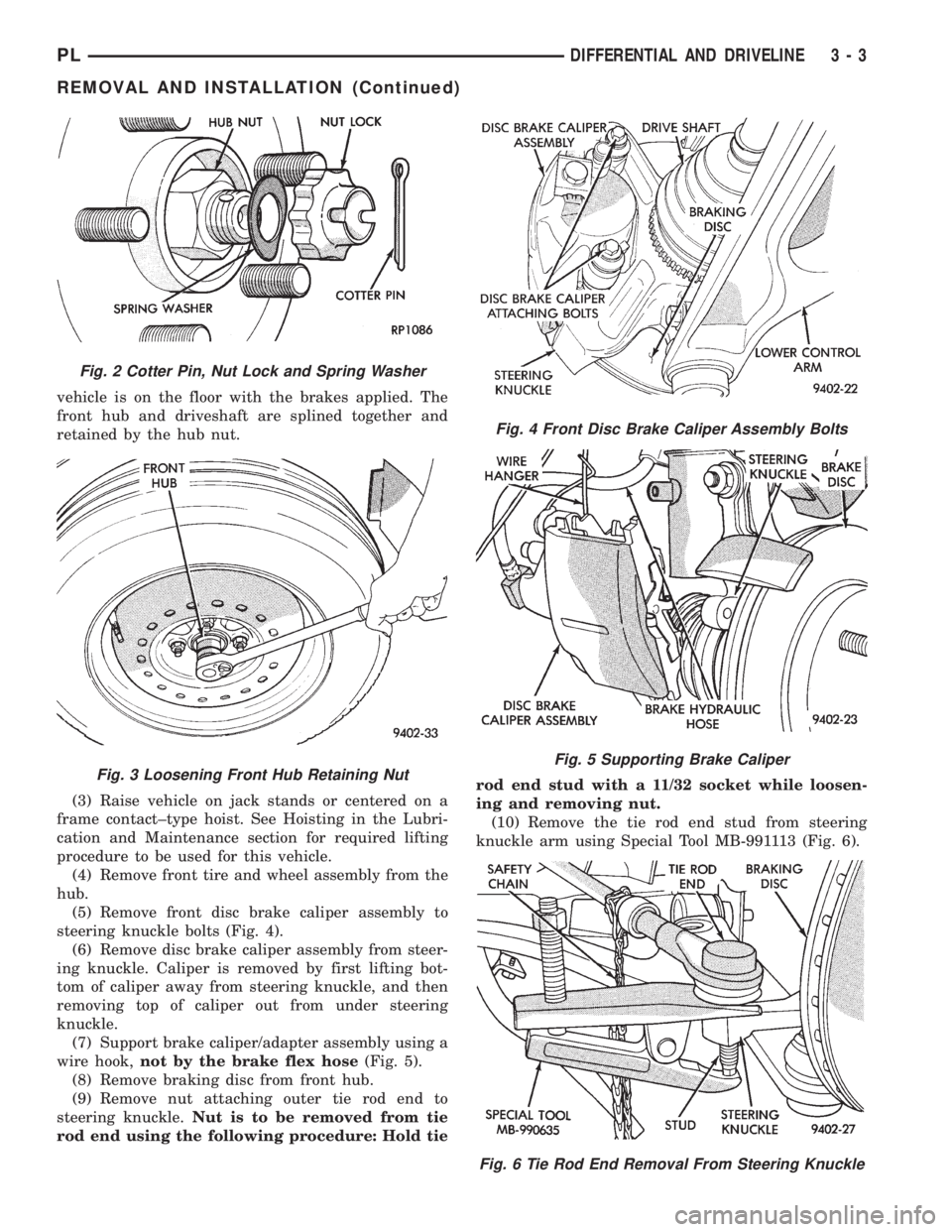
steering knuckle bolts (Fig. 4).
(6) Remove disc brake caliper assembly from steer-
ing knuckle. Caliper is removed by first lifting bot-
tom of caliper away from steering knuckle, and then
removing top of caliper out from under steering
knuckle.
(7) Support brake caliper/adapter assembly using a
wire hook,not by the brake flex hose(Fig. 5).
(8) Remove braking disc from front hub.
(9) Remove nut attaching outer tie rod end to
steering knuckle.Nut is to be removed from tie
rod end using the following procedure: Hold tierod end stud with a 11/32 socket while loosen-
ing and removing nut.
(10) Remove the tie rod end stud from steering
knuckle arm using Special Tool MB-991113 (Fig. 6).
Fig. 2 Cotter Pin, Nut Lock and Spring Washer
Fig. 3 Loosening Front Hub Retaining Nut
Fig. 4 Front Disc Brake Caliper Assembly Bolts
Fig. 5 Supporting Brake Caliper
Fig. 6 Tie Rod End Removal From Steering Knuckle
PLDIFFERENTIAL AND DRIVELINE 3 - 3
REMOVAL AND INSTALLATION (Continued)
Page 69 of 1200
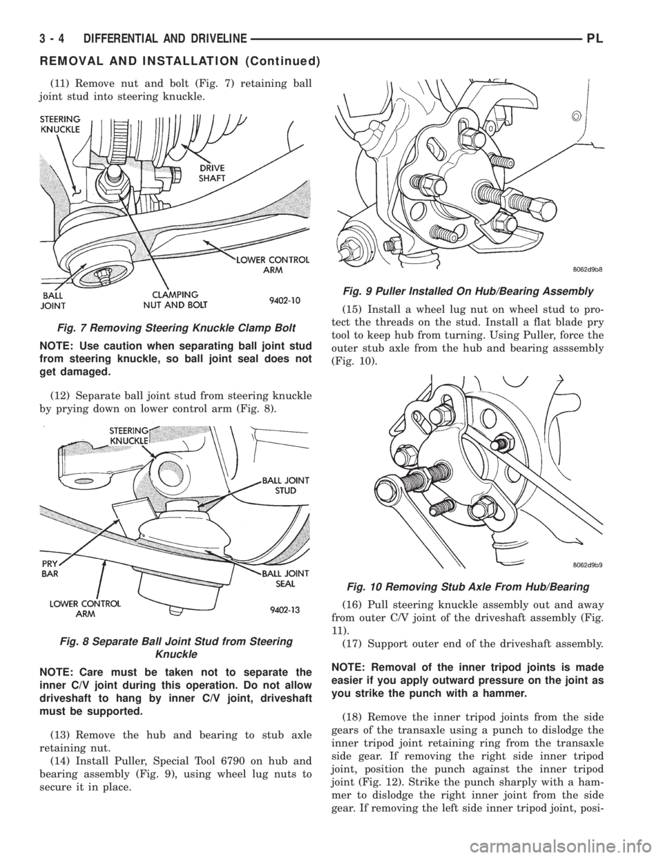
(11) Remove nut and bolt (Fig. 7) retaining ball
joint stud into steering knuckle.
NOTE: Use caution when separating ball joint stud
from steering knuckle, so ball joint seal does not
get damaged.
(12) Separate ball joint stud from steering knuckle
by prying down on lower control arm (Fig. 8).
NOTE: Care must be taken not to separate the
inner C/V joint during this operation. Do not allow
driveshaft to hang by inner C/V joint, driveshaft
must be supported.
(13) Remove the hub and bearing to stub axle
retaining nut.
(14) Install Puller, Special Tool 6790 on hub and
bearing assembly (Fig. 9), using wheel lug nuts to
secure it in place.(15) Install a wheel lug nut on wheel stud to pro-
tect the threads on the stud. Install a flat blade pry
tool to keep hub from turning. Using Puller, force the
outer stub axle from the hub and bearing asssembly
(Fig. 10).
(16) Pull steering knuckle assembly out and away
from outer C/V joint of the driveshaft assembly (Fig.
11).
(17) Support outer end of the driveshaft assembly.
NOTE: Removal of the inner tripod joints is made
easier if you apply outward pressure on the joint as
you strike the punch with a hammer.
(18) Remove the inner tripod joints from the side
gears of the transaxle using a punch to dislodge the
inner tripod joint retaining ring from the transaxle
side gear. If removing the right side inner tripod
joint, position the punch against the inner tripod
joint (Fig. 12). Strike the punch sharply with a ham-
mer to dislodge the right inner joint from the side
gear. If removing the left side inner tripod joint, posi-
Fig. 7 Removing Steering Knuckle Clamp Bolt
Fig. 8 Separate Ball Joint Stud from Steering
Knuckle
Fig. 9 Puller Installed On Hub/Bearing Assembly
Fig. 10 Removing Stub Axle From Hub/Bearing
3 - 4 DIFFERENTIAL AND DRIVELINEPL
REMOVAL AND INSTALLATION (Continued)
Page 70 of 1200
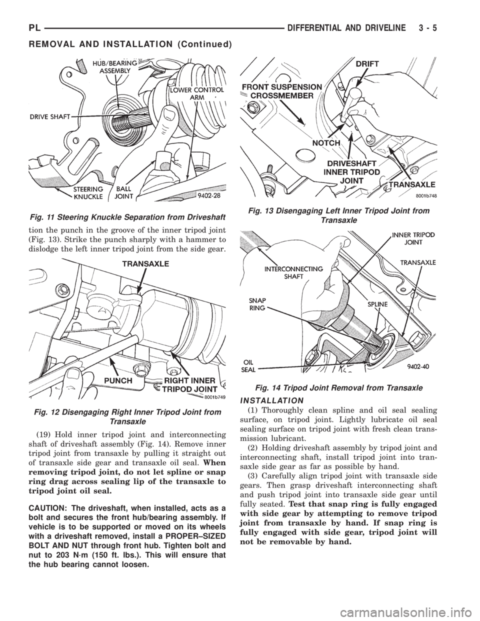
tion the punch in the groove of the inner tripod joint
(Fig. 13). Strike the punch sharply with a hammer to
dislodge the left inner tripod joint from the side gear.
(19) Hold inner tripod joint and interconnecting
shaft of driveshaft assembly (Fig. 14). Remove inner
tripod joint from transaxle by pulling it straight out
of transaxle side gear and transaxle oil seal.When
removing tripod joint, do not let spline or snap
ring drag across sealing lip of the transaxle to
tripod joint oil seal.
CAUTION: The driveshaft, when installed, acts as a
bolt and secures the front hub/bearing assembly. If
vehicle is to be supported or moved on its wheels
with a driveshaft removed, install a PROPER±SIZED
BOLT AND NUT through front hub. Tighten bolt and
nut to 203 N´m (150 ft. lbs.). This will ensure that
the hub bearing cannot loosen.
INSTALLATION
(1) Thoroughly clean spline and oil seal sealing
surface, on tripod joint. Lightly lubricate oil seal
sealing surface on tripod joint with fresh clean trans-
mission lubricant.
(2) Holding driveshaft assembly by tripod joint and
interconnecting shaft, install tripod joint into tran-
saxle side gear as far as possible by hand.
(3) Carefully align tripod joint with transaxle side
gears. Then grasp driveshaft interconnecting shaft
and push tripod joint into transaxle side gear until
fully seated.Test that snap ring is fully engaged
with side gear by attempting to remove tripod
joint from transaxle by hand. If snap ring is
fully engaged with side gear, tripod joint will
not be removable by hand.
Fig. 11 Steering Knuckle Separation from Driveshaft
Fig. 12 Disengaging Right Inner Tripod Joint from
Transaxle
Fig. 13 Disengaging Left Inner Tripod Joint from
Transaxle
Fig. 14 Tripod Joint Removal from Transaxle
PLDIFFERENTIAL AND DRIVELINE 3 - 5
REMOVAL AND INSTALLATION (Continued)