diagram DODGE NEON 1999 Service Workshop Manual
[x] Cancel search | Manufacturer: DODGE, Model Year: 1999, Model line: NEON, Model: DODGE NEON 1999Pages: 1200, PDF Size: 35.29 MB
Page 704 of 1200
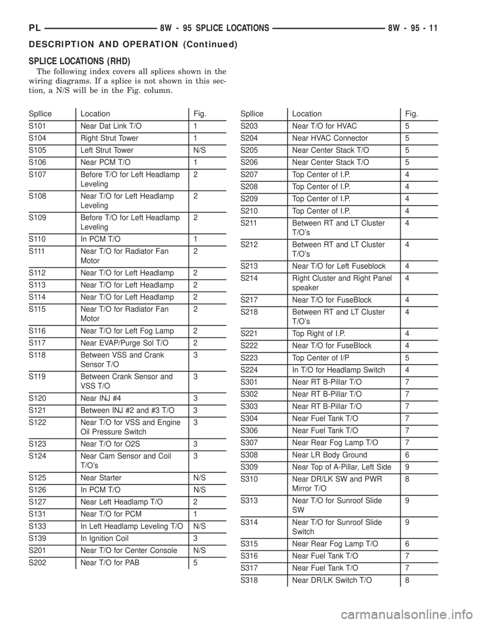
SPLICE LOCATIONS (RHD)
The following index covers all splices shown in the
wiring diagrams. If a splice is not shown in this sec-
tion, a N/S will be in the Fig. column.
Spllice Location Fig.
S101 Near Dat Link T/O 1
S104 Right Strut Tower 1
S105 Left Strut Tower N/S
S106 Near PCM T/O 1
S107 Before T/O for Left Headlamp
Leveling2
S108 Near T/O for Left Headlamp
Leveling2
S109 Before T/O for Left Headlamp
Leveling2
S110 In PCM T/O 1
S111 Near T/O for Radiator Fan
Motor2
S112 Near T/O for Left Headlamp 2
S113 Near T/O for Left Headlamp 2
S114 Near T/O for Left Headlamp 2
S115 Near T/O for Radiator Fan
Motor2
S116 Near T/O for Left Fog Lamp 2
S117 Near EVAP/Purge Sol T/O 2
S118 Between VSS and Crank
Sensor T/O3
S119 Between Crank Sensor and
VSS T/O3
S120 Near INJ #4 3
S121 Between INJ #2 and #3 T/O 3
S122 Near T/O for VSS and Engine
Oil Pressure Switch3
S123 Near T/O for O2S 3
S124 Near Cam Sensor and Coil
T/O's3
S125 Near Starter N/S
S126 In PCM T/O N/S
S127 Near Left Headlamp T/O 2
S131 Near T/O for PCM 1
S133 In Left Headlamp Leveling T/O N/S
S139 In Ignition Coil 3
S201 Near T/O for Center Console N/S
S202 Near T/O for PAB 5
Spllice Location Fig.
S203 Near T/O for HVAC 5
S204 Near HVAC Connector 5
S205 Near Center Stack T/O 5
S206 Near Center Stack T/O 5
S207 Top Center of I.P. 4
S208 Top Center of I.P. 4
S209 Top Center of I.P. 4
S210 Top Center of I.P. 4
S211 Between RT and LT Cluster
T/O's4
S212 Between RT and LT Cluster
T/O's4
S213 Near T/O for Left Fuseblock 4
S214 Right Cluster and Right Panel
speaker4
S217 Near T/O for FuseBlock 4
S218 Between RT and LT Cluster
T/O's4
S221 Top Right of I.P. 4
S222 Near T/O for FuseBlock 4
S223 Top Center of I/P 5
S224 In T/O for Headlamp Switch 4
S301 Near RT B-Pillar T/O 7
S302 Near RT B-Pillar T/O 7
S303 Near RT B-Pillar T/O 7
S304 Near Fuel Tank T/O 7
S306 Near Fuel Tank T/O 7
S307 Near Rear Fog Lamp T/O 7
S308 Near LR Body Ground 6
S309 Near Top of A-Pillar, Left Side 9
S310 Near DR/LK SW and PWR
Mirror T/O8
S313 Near T/O for Sunroof Slide
SW9
S314 Near T/O for Sunroof Slide
Switch9
S315 Near Rear Fog Lamp T/O 6
S316 Near Fuel Tank T/O 7
S317 Near Fuel Tank T/O 7
S318 Near DR/LK Switch T/O 8
PL8W - 95 SPLICE LOCATIONS 8W - 95 - 11
DESCRIPTION AND OPERATION (Continued)
Page 847 of 1200
DIAGNOSIS AND TESTING
FUEL PUMP PRESSURE TEST
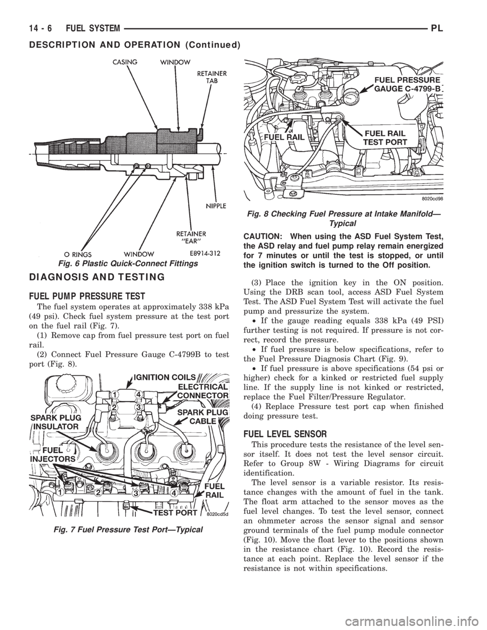
The fuel system operates at approximately 338 kPa
(49 psi). Check fuel system pressure at the test port
on the fuel rail (Fig. 7).
(1) Remove cap from fuel pressure test port on fuel
rail.
(2) Connect Fuel Pressure Gauge C-4799B to test
port (Fig. 8).CAUTION: When using the ASD Fuel System Test,
the ASD relay and fuel pump relay remain energized
for 7 minutes or until the test is stopped, or until
the ignition switch is turned to the Off position.
(3) Place the ignition key in the ON position.
Using the DRB scan tool, access ASD Fuel System
Test. The ASD Fuel System Test will activate the fuel
pump and pressurize the system.
²If the gauge reading equals 338 kPa (49 PSI)
further testing is not required. If pressure is not cor-
rect, record the pressure.
²If fuel pressure is below specifications, refer to
the Fuel Pressure Diagnosis Chart (Fig. 9).
²If fuel pressure is above specifications (54 psi or
higher) check for a kinked or restricted fuel supply
line. If the supply line is not kinked or restricted,
replace the Fuel Filter/Pressure Regulator.
(4) Replace Pressure test port cap when finished
doing pressure test.
FUEL LEVEL SENSOR
This procedure tests the resistance of the level sen-
sor itself. It does not test the level sensor circuit.
Refer to Group 8W - Wiring Diagrams for circuit
identification.
The level sensor is a variable resistor. Its resis-
tance changes with the amount of fuel in the tank.
The float arm attached to the sensor moves as the
fuel level changes. To test the level sensor, connect
an ohmmeter across the sensor signal and sensor
ground terminals of the fuel pump module connector
(Fig. 10). Move the float lever to the positions shown
in the resistance chart (Fig. 10). Record the resis-
tance at each point. Replace the level sensor if the
resistance is not within specifications.
Fig. 8 Checking Fuel Pressure at Intake ManifoldÐ
Typical
Fig. 6 Plastic Quick-Connect Fittings
Fig. 7 Fuel Pressure Test PortÐTypical
14 - 6 FUEL SYSTEMPL
DESCRIPTION AND OPERATION (Continued)
Page 873 of 1200
disables the A/C compressor clutch for several sec-
onds.
The air conditioning clutch relay is located in the
PDC. The inside top of the PDC cover has a label
showing relay and fuse location.
AUTOMATIC SHUTDOWN RELAYÐPCM OUTPUT
The automatic shutdown (ASD) relay supplies bat-
tery voltage to the fuel injectors, electronic ignition
coil and the heating elements in the oxygen sensors.
A buss bar in the power distribution center (PDC)
supplies voltage to the solenoid side and contact side
of the relay. The ASD relay power circuit contains a
20 amp fuse between the buss bar in the PDC and
the relay. The fuse also protects the power circuit for
the fuel pump relay and pump. The fuse is located in
the PDC. Refer to Group 8W, Wiring Diagrams for
circuit information.
The PCM controls the relay by switching the
ground path for the solenoid side of the relay on and
off. The PCM turns the ground path off when the
ignition switch is in the Off position unless the 02
Heater Monitor test is being run. Refer to Group 25,
On-Board Diagnostics. When the ignition switch is in
the On or Crank position, the PCM monitors the
crankshaft position sensor and camshaft position sen-
sor signals to determine engine speed and ignition
timing (coil dwell). If the PCM does not receive the
crankshaft position sensor and camshaft position sen-
sor signals when the ignition switch is in the Run
position, it will de- energize the ASD relay.
The ASD relay is located in the PDC. The inside
top of the PDC cover has a label showing relay and
fuse location.
CHARGING SYSTEM INDICATOR LAMPÐPCM
OUTPUT
The PCM turns the instrument panel Charging
System Lamp on. Refer to Group 8C for charging sys-
tem information.
FUEL PUMP RELAYÐPCM OUTPUT
The fuel pump relay supplies battery voltage to the
fuel pump. A buss bar in the Power Distribution Cen-
ter (PDC) supplies voltage to the solenoid side and
contact side of the relay. The fuel pump relay power
circuit contains a 20 amp fuse between the buss bar
in the PDC and the relay. The fuse also protects the
power circuit for the Automatic Shutdown (ASD)
relay. The fuse is located in the PDC. Refer to Group
8W, Wiring Diagrams for circuit information.
The PCM controls the fuel pump relay by switch-
ing the ground path for the solenoid side of the relay
on and off. The PCM turns the ground path off when
the ignition switch is in the Off position. When the
ignition switch is in the On position, the PCM ener-gizes the fuel pump. If the crankshaft position sensor
does not detect engine rotation, the PCM de-ener-
gizes the relay after approximately one second.
The fuel pump relay is located in the PDC. The
inside top of the PDC cover has a label showing relay
and fuse location.
DUTY CYCLE EVAP PURGE SOLENOIDÐPCM
OUTPUT
The duty cycle EVAP purge solenoid regulates the
rate of vapor flow from the EVAP canister to the
throttle body. The powertrain control module oper-
ates the solenoid.
During the cold start warm-up period and the hot
start time delay, the PCM does not energize the sole-
noid. When de-energized, no vapors are purged.
The engine enters closed loop operation after it
reaches a specified temperature and the programmed
time delay ends. During closed loop operation, the
PCM energizes and de-energizes the solenoid 5 to 10
times per second, depending upon operating condi-
tions. The PCM varies the vapor flow rate by chang-
ing solenoid pulse width. Pulse width is the amount
of time the solenoid is energized.
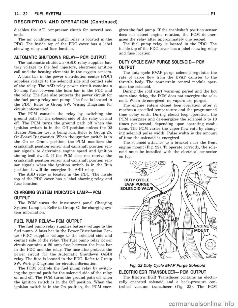
The solenoid attaches to a bracket near the front
engine mount (Fig. 22). To operate correctly, the sole-
noid must be installed with the electrical connector
on top.
ELECTRIC EGR TRANSDUCERÐPCM OUTPUT
The Electric EGR Transducer contains an electri-
cally operated solenoid and a back-pressure con-
trolled vacuum transducer (Fig. 23). The PCM
Fig. 22 Duty Cycle EVAP Purge Solenoid
14 - 32 FUEL SYSTEMPL
DESCRIPTION AND OPERATION (Continued)
Page 888 of 1200
(7) Attach the other end of the jumper wire to
relay terminal 86. This activates the relay. The ohm-
meter should now show continuity between relay ter-
minals 87 and 30. The ohmmeter should not show
continuity between relay terminals 87A and 30.
(8) Disconnect jumper wires.
(9) Replace the relay if it did not pass the continu-
ity and resistance tests. If the relay passed the tests,
it operates properly. Check the remainder of the ASD
and fuel pump relay circuits. Refer to group 8W, Wir-
ing Diagrams.
CAMSHAFT AND CRANKSHAFT POSITION SENSOR
Refer to Group 8D, Ignition for Diagnosis and Test-
ing of Camshaft and Crankshaft Sensors.
ENGINE COOLANT TEMPERATURE SENSOR
(1) With the key off, disconnect wire harness con-
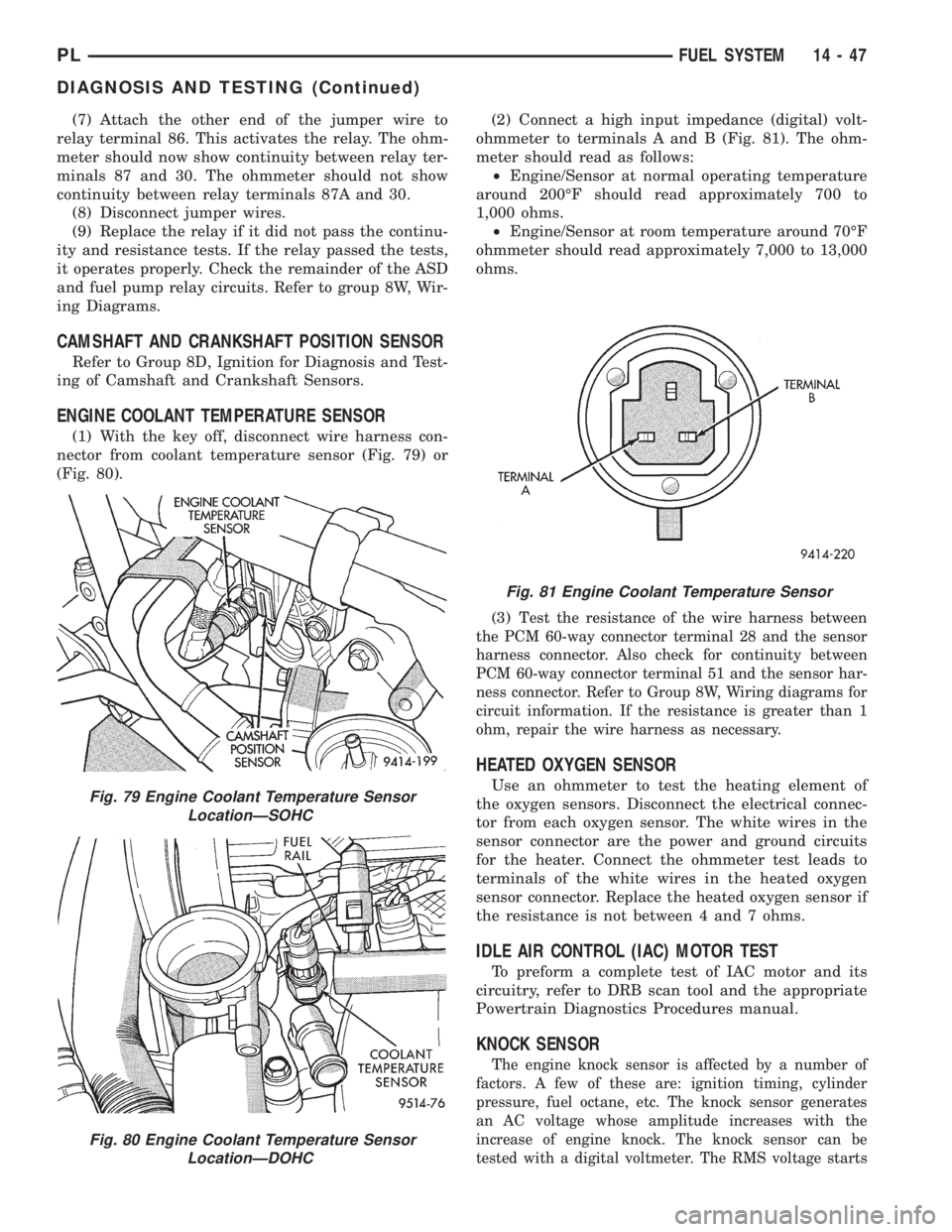
nector from coolant temperature sensor (Fig. 79) or
(Fig. 80).(2) Connect a high input impedance (digital) volt-
ohmmeter to terminals A and B (Fig. 81). The ohm-
meter should read as follows:
²Engine/Sensor at normal operating temperature
around 200ÉF should read approximately 700 to
1,000 ohms.
²Engine/Sensor at room temperature around 70ÉF
ohmmeter should read approximately 7,000 to 13,000
ohms.
(3) T
est the resistance of the wire harness between
the PCM 60-way connector terminal 28 and the sensor
harness connector. Also check for continuity between
PCM 60-way connector terminal 51 and the sensor har-
ness connector. Refer to Group 8W, Wiring diagrams for
circuit information. If the resistance is greater than 1
ohm, repair the wire harness as necessary.
HEATED OXYGEN SENSOR
Use an ohmmeter to test the heating element of
the oxygen sensors. Disconnect the electrical connec-
tor from each oxygen sensor. The white wires in the
sensor connector are the power and ground circuits
for the heater. Connect the ohmmeter test leads to
terminals of the white wires in the heated oxygen
sensor connector. Replace the heated oxygen sensor if
the resistance is not between 4 and 7 ohms.
IDLE AIR CONTROL (IAC) MOTOR TEST
To preform a complete test of IAC motor and its
circuitry, refer to DRB scan tool and the appropriate
Powertrain Diagnostics Procedures manual.
KNOCK SENSOR
The engine knock sensor is affected by a number of
factors. A few of these are: ignition timing, cylinder
pressure, fuel octane, etc. The knock sensor generates
an AC voltage whose amplitude increases with the
increase of engine knock. The knock sensor can be
tested with a digital voltmeter. The RMS voltage starts
Fig. 79 Engine Coolant Temperature Sensor
LocationÐSOHC
Fig. 80 Engine Coolant Temperature Sensor
LocationÐDOHC
Fig. 81 Engine Coolant Temperature Sensor
PLFUEL SYSTEM 14 - 47
DIAGNOSIS AND TESTING (Continued)
Page 983 of 1200
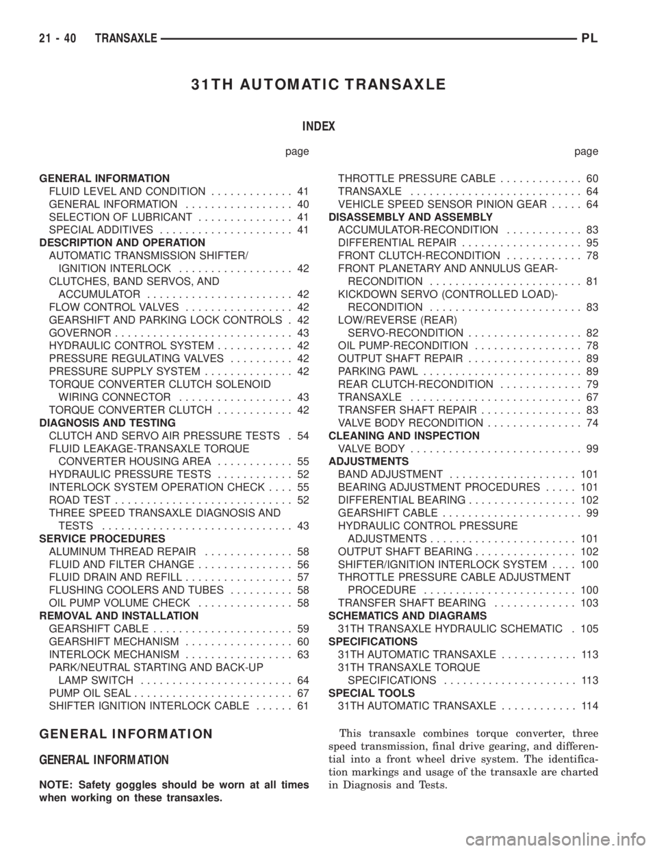
31TH AUTOMATIC TRANSAXLE
INDEX
page page
GENERAL INFORMATION
FLUID LEVEL AND CONDITION............. 41
GENERAL INFORMATION................. 40
SELECTION OF LUBRICANT............... 41
SPECIAL ADDITIVES..................... 41
DESCRIPTION AND OPERATION
AUTOMATIC TRANSMISSION SHIFTER/
IGNITION INTERLOCK.................. 42
CLUTCHES, BAND SERVOS, AND
ACCUMULATOR....................... 42
FLOW CONTROL VALVES................. 42
GEARSHIFT AND PARKING LOCK CONTROLS . 42
GOVERNOR............................ 43
HYDRAULIC CONTROL SYSTEM............ 42
PRESSURE REGULATING VALVES.......... 42
PRESSURE SUPPLY SYSTEM.............. 42
TORQUE CONVERTER CLUTCH SOLENOID
WIRING CONNECTOR.................. 43
TORQUE CONVERTER CLUTCH............ 42
DIAGNOSIS AND TESTING
CLUTCH AND SERVO AIR PRESSURE TESTS . 54
FLUID LEAKAGE-TRANSAXLE TORQUE
CONVERTER HOUSING AREA............ 55
HYDRAULIC PRESSURE TESTS............ 52
INTERLOCK SYSTEM OPERATION CHECK.... 55
ROAD TEST............................ 52
THREE SPEED TRANSAXLE DIAGNOSIS AND
TESTS.............................. 43
SERVICE PROCEDURES
ALUMINUM THREAD REPAIR.............. 58
FLUID AND FILTER CHANGE............... 56
FLUID DRAIN AND REFILL................. 57
FLUSHING COOLERS AND TUBES.......... 58
OIL PUMP VOLUME CHECK............... 58
REMOVAL AND INSTALLATION
GEARSHIFT CABLE...................... 59
GEARSHIFT MECHANISM................. 60
INTERLOCK MECHANISM................. 63
PARK/NEUTRAL STARTING AND BACK-UP
LAMP SWITCH........................ 64
PUMP OIL SEAL......................... 67
SHIFTER IGNITION INTERLOCK CABLE...... 61THROTTLE PRESSURE CABLE............. 60
TRANSAXLE........................... 64
VEHICLE SPEED SENSOR PINION GEAR..... 64
DISASSEMBLY AND ASSEMBLY
ACCUMULATOR-RECONDITION............ 83
DIFFERENTIAL REPAIR................... 95
FRONT CLUTCH-RECONDITION............ 78
FRONT PLANETARY AND ANNULUS GEAR-
RECONDITION........................ 81
KICKDOWN SERVO (CONTROLLED LOAD)-
RECONDITION........................ 83
LOW/REVERSE (REAR)
SERVO-RECONDITION.................. 82
OIL PUMP-RECONDITION................. 78
OUTPUT SHAFT REPAIR.................. 89
PARKING PAWL......................... 89
REAR CLUTCH-RECONDITION............. 79
TRANSAXLE........................... 67
TRANSFER SHAFT REPAIR................ 83
VALVE BODY RECONDITION............... 74
CLEANING AND INSPECTION
VALVE BODY........................... 99
ADJUSTMENTS
BAND ADJUSTMENT.................... 101
BEARING ADJUSTMENT PROCEDURES..... 101
DIFFERENTIAL BEARING................. 102
GEARSHIFT CABLE...................... 99
HYDRAULIC CONTROL PRESSURE
ADJUSTMENTS....................... 101
OUTPUT SHAFT BEARING................ 102
SHIFTER/IGNITION INTERLOCK SYSTEM.... 100
THROTTLE PRESSURE CABLE ADJUSTMENT
PROCEDURE........................ 100
TRANSFER SHAFT BEARING............. 103
SCHEMATICS AND DIAGRAMS
31TH TRANSAXLE HYDRAULIC SCHEMATIC . 105
SPECIFICATIONS
31TH AUTOMATIC TRANSAXLE............ 113
31TH TRANSAXLE TORQUE
SPECIFICATIONS..................... 113
SPECIAL TOOLS
31TH AUTOMATIC TRANSAXLE............ 114
GENERAL INFORMATION
GENERAL INFORMATION
NOTE: Safety goggles should be worn at all times
when working on these transaxles.This transaxle combines torque converter, three
speed transmission, final drive gearing, and differen-
tial into a front wheel drive system. The identifica-
tion markings and usage of the transaxle are charted
in Diagnosis and Tests.
21 - 40 TRANSAXLEPL
Page 1048 of 1200
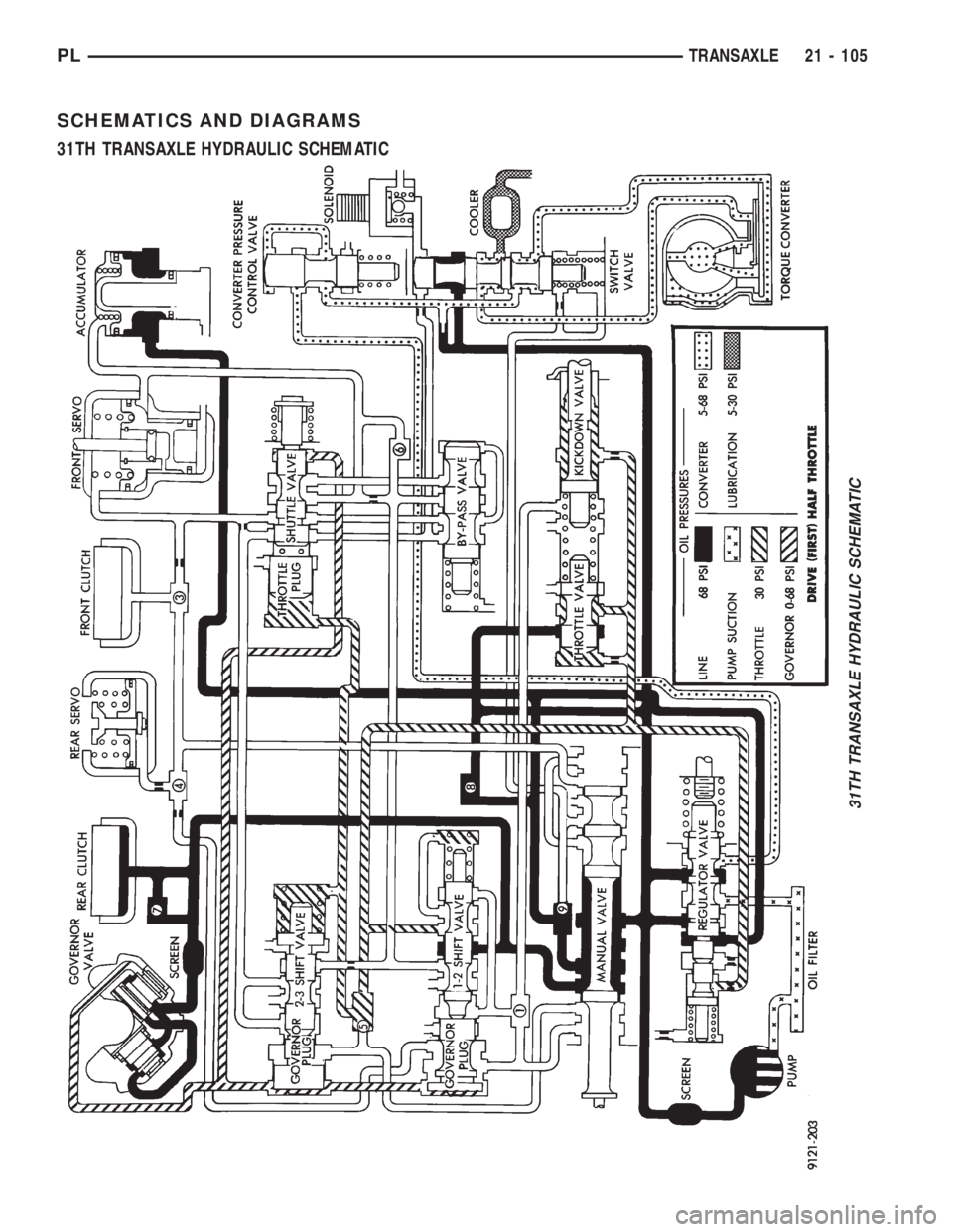
SCHEMATICS AND DIAGRAMS
31TH TRANSAXLE HYDRAULIC SCHEMATIC
31TH TRANSAXLE HYDRAULIC SCHEMATIC
PLTRANSAXLE 21 - 105
Page 1049 of 1200
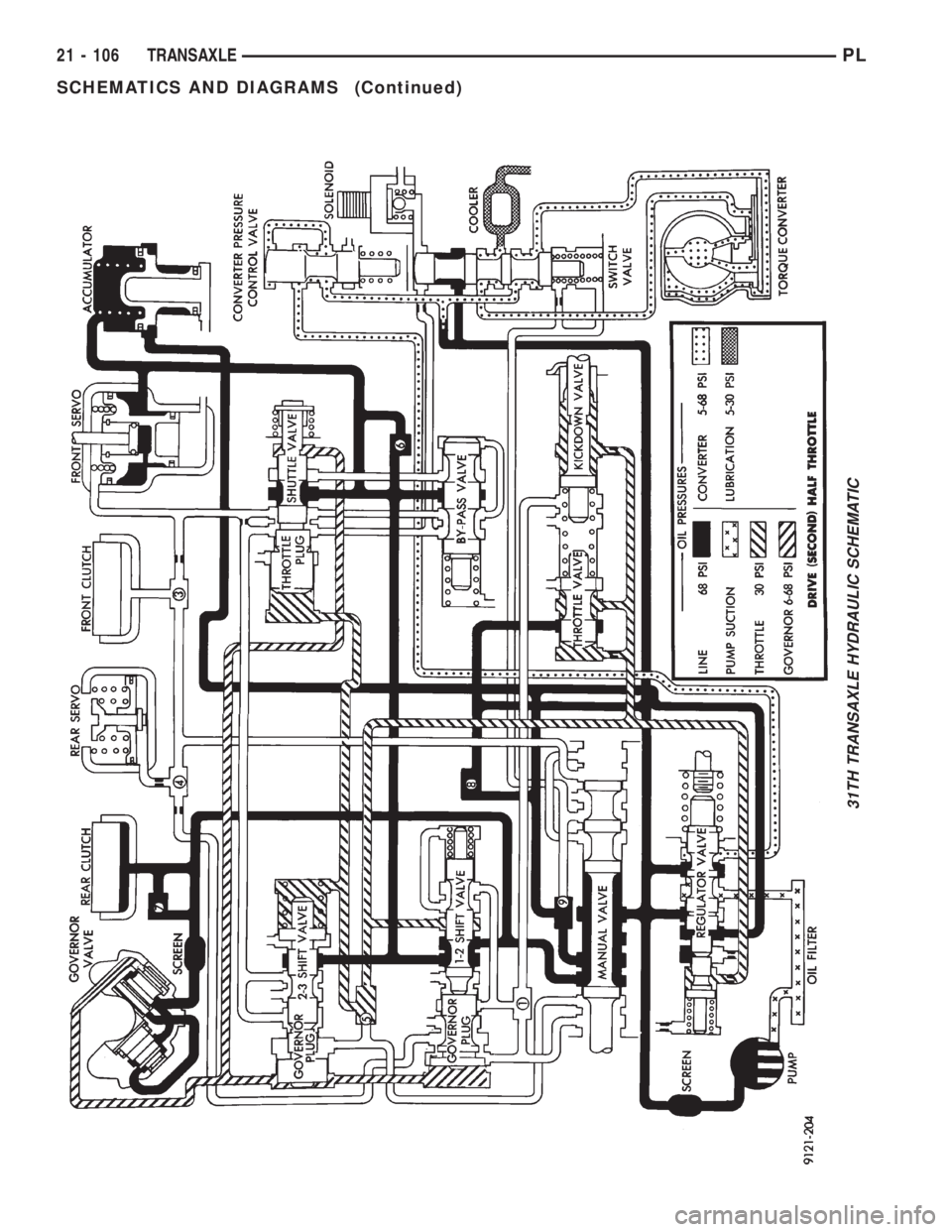
31TH TRANSAXLE HYDRAULIC SCHEMATIC
21 - 106 TRANSAXLEPL
SCHEMATICS AND DIAGRAMS (Continued)
Page 1050 of 1200
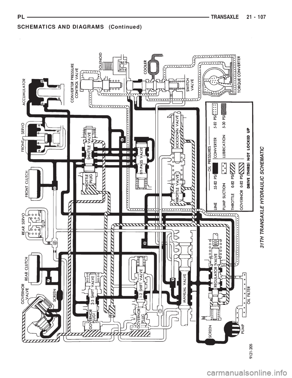
31TH TRANSAXLE HYDRAULIC SCHEMATIC
PLTRANSAXLE 21 - 107
SCHEMATICS AND DIAGRAMS (Continued)
Page 1051 of 1200

31TH TRANSAXLE HYDRAULIC SCHEMATIC
21 - 108 TRANSAXLEPL
SCHEMATICS AND DIAGRAMS (Continued)
Page 1052 of 1200

31TH TRANSAXLE HYDRAULIC SCHEMATIC
PLTRANSAXLE 21 - 109
SCHEMATICS AND DIAGRAMS (Continued)