DODGE RAM 2001 Service Repair Manual
Manufacturer: DODGE, Model Year: 2001, Model line: RAM, Model: DODGE RAM 2001Pages: 2889, PDF Size: 68.07 MB
Page 1281 of 2889
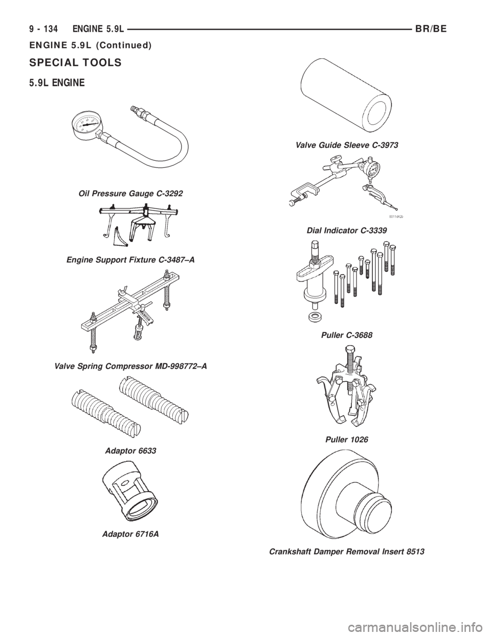
SPECIAL TOOLS
5.9L ENGINE
Oil Pressure Gauge C-3292
Engine Support Fixture C-3487±A
Valve Spring Compressor MD-998772±A
Adaptor 6633
Adaptor 6716A
Valve Guide Sleeve C-3973
Dial Indicator C-3339
Puller C-3688
Puller 1026
Crankshaft Damper Removal Insert 8513
9 - 134 ENGINE 5.9LBR/BE
ENGINE 5.9L (Continued)
Page 1282 of 2889
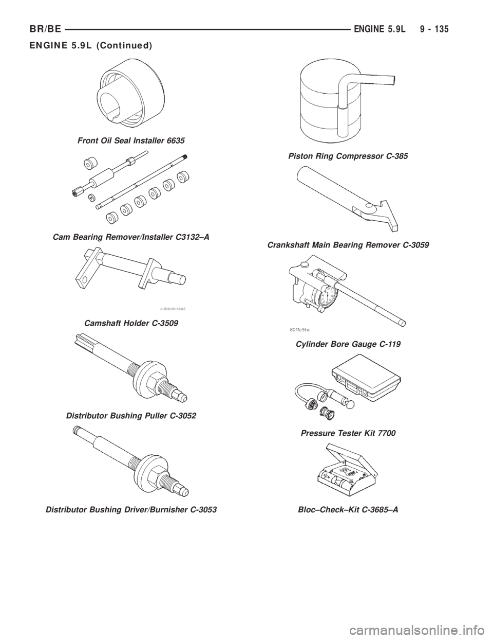
Front Oil Seal Installer 6635
Cam Bearing Remover/Installer C3132±A
Camshaft Holder C-3509
Distributor Bushing Puller C-3052
Distributor Bushing Driver/Burnisher C-3053
Piston Ring Compressor C-385
Crankshaft Main Bearing Remover C-3059
Cylinder Bore Gauge C-119
Pressure Tester Kit 7700
Bloc±Check±Kit C-3685±A
BR/BEENGINE 5.9L 9 - 135
ENGINE 5.9L (Continued)
Page 1283 of 2889
CYLINDER HEAD
DESCRIPTIONÐCYLINDER HEAD
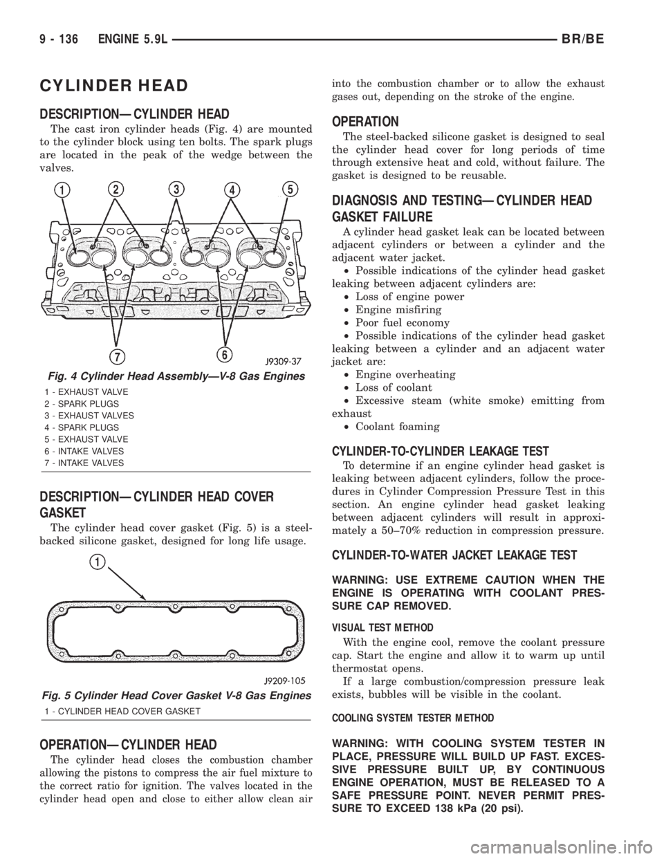
The cast iron cylinder heads (Fig. 4) are mounted
to the cylinder block using ten bolts. The spark plugs
are located in the peak of the wedge between the
valves.
DESCRIPTIONÐCYLINDER HEAD COVER
GASKET
The cylinder head cover gasket (Fig. 5) is a steel-
backed silicone gasket, designed for long life usage.
OPERATIONÐCYLINDER HEAD
The cylinder head closes the combustion chamber
allowing the pistons to compress the air fuel mixture to
the correct ratio for ignition. The valves located in the
cylinder head open and close to either allow clean airinto the combustion chamber or to allow the exhaust
gases out, depending on the stroke of the engine.
OPERATION
The steel-backed silicone gasket is designed to seal
the cylinder head cover for long periods of time
through extensive heat and cold, without failure. The
gasket is designed to be reusable.
DIAGNOSIS AND TESTINGÐCYLINDER HEAD
GASKET FAILURE
A cylinder head gasket leak can be located between
adjacent cylinders or between a cylinder and the
adjacent water jacket.
²Possible indications of the cylinder head gasket
leaking between adjacent cylinders are:
²Loss of engine power
²Engine misfiring
²Poor fuel economy
²Possible indications of the cylinder head gasket
leaking between a cylinder and an adjacent water
jacket are:
²Engine overheating
²Loss of coolant
²Excessive steam (white smoke) emitting from
exhaust
²Coolant foaming
CYLINDER-TO-CYLINDER LEAKAGE TEST
To determine if an engine cylinder head gasket is
leaking between adjacent cylinders, follow the proce-
dures in Cylinder Compression Pressure Test in this
section. An engine cylinder head gasket leaking
between adjacent cylinders will result in approxi-
mately a 50±70% reduction in compression pressure.
CYLINDER-TO-WATER JACKET LEAKAGE TEST
WARNING: USE EXTREME CAUTION WHEN THE
ENGINE IS OPERATING WITH COOLANT PRES-
SURE CAP REMOVED.
VISUAL TEST METHOD
With the engine cool, remove the coolant pressure
cap. Start the engine and allow it to warm up until
thermostat opens.
If a large combustion/compression pressure leak
exists, bubbles will be visible in the coolant.
COOLING SYSTEM TESTER METHOD
WARNING: WITH COOLING SYSTEM TESTER IN
PLACE, PRESSURE WILL BUILD UP FAST. EXCES-
SIVE PRESSURE BUILT UP, BY CONTINUOUS
ENGINE OPERATION, MUST BE RELEASED TO A
SAFE PRESSURE POINT. NEVER PERMIT PRES-
SURE TO EXCEED 138 kPa (20 psi).
Fig. 4 Cylinder Head AssemblyÐV-8 Gas Engines
1 - EXHAUST VALVE
2 - SPARK PLUGS
3 - EXHAUST VALVES
4 - SPARK PLUGS
5 - EXHAUST VALVE
6 - INTAKE VALVES
7 - INTAKE VALVES
Fig. 5 Cylinder Head Cover Gasket V-8 Gas Engines
1 - CYLINDER HEAD COVER GASKET
9 - 136 ENGINE 5.9LBR/BE
Page 1284 of 2889
Install Cooling System Tester 7700 or equivalent to
pressure cap neck. Start the engine and observe the
tester's pressure gauge. If gauge pulsates with every
power stroke of a cylinder a combustion pressure
leak is evident.
CHEMICAL TEST METHOD
Combustion leaks into the cooling system can also
be checked by using Bloc-Chek Kit C-3685-A or
equivalent. Perform test following the procedures
supplied with the tool kit.
REMOVAL
(1) Disconnect the battery negative cable.
(2) Drain cooling system (Refer to 7 - COOLING -
STANDARD PROCEDURE).
(3)
Remove the air cleaner resonator and duct work.
(4) Remove the intake manifold-to-generator
bracket support rod. Remove the generator.
(5) Remove closed crankcase ventilation system.
(6) Disconnect the evaporation control system.
(7) Perform the Fuel System Pressure Release pro-
cedure (Refer to 14 - FUEL SYSTEM/FUEL DELIV-
ERY - STANDARD PROCEDURE). Disconnect the
fuel supply line (Refer to 14 - FUEL SYSTEM/FUEL
DELIVERY/QUICK CONNECT FITTING - STAN-
DARD PROCEDURE).
(8) Disconnect accelerator linkage and if so
equipped, the speed control and transmission kick-
down cables.
(9) Remove distributor cap and wires.
(10) Disconnect the coil wires.
(11) Disconnect heat indicator sending unit wire.
(12) Disconnect heater hoses and bypass hose.
(13) Remove cylinder head covers and gaskets
(Refer to 9 - ENGINE/CYLINDER HEAD/CYLIN-
DER HEAD COVER(S) - REMOVAL).
(14)
Remove intake manifold (Refer to 9 - ENGINE/
MANIFOLDS/INTAKE MANIFOLD - REMOVAL) and
throttle body as an assembly. Discard the flange side
gaskets and the front and rear cross-over gaskets.
(15) Remove exhaust manifolds (Refer to 9 -
ENGINE/MANIFOLDS/EXHAUST MANIFOLD -
REMOVAL).
(16) Remove rocker arm assemblies and push rods.
Identify to ensure installation in original locations.
(17) Remove the head bolts from each cylinder
head and remove cylinder heads. Discard the cylin-
der head gasket.
(18) Remove spark plugs.
CLEANING
Clean all surfaces of cylinder block and cylinder
heads.
Clean cylinder block front and rear gasket surfaces
using a suitable solvent.
INSPECTION
Inspect all surfaces with a straightedge if there is
any reason to suspect leakage. If out-of-flatness
exceeds 0.00075mm/mm (0.0001in./in.) times the
span length in any direction, either replace head or
lightly machine the head surface.
FOR EXAMPLE:ÐA 305 mm (12 in.) span is
0.102 mm (0.004 in.) out-of-flat. The allowable out-of-
flat is 305 x 0.00075 (12 x 0.00075) equals 0.23 mm
(0.009 in.). This amount of out-of-flat is acceptable.
The cylinder head surface finish should be
1.78-3.00 microns (70-125 microinches).
Inspect push rods. Replace worn or bent rods.
INSTALLATION
(1) Clean all surfaces of cylinder block and cylin-
der heads.
(2) Clean cylinder block front and rear gasket sur-
faces using a suitable solvent.
(3) Position new cylinder head gaskets onto the
cylinder block.
(4) Position cylinder heads onto head gaskets and
cylinder block.
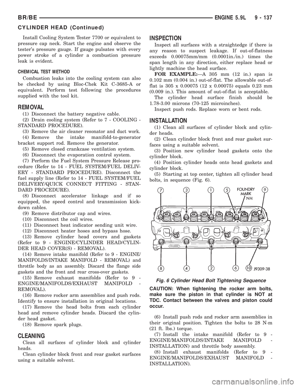
(5) Starting at top center, tighten all cylinder head
bolts, in sequence (Fig. 6).
CAUTION: When tightening the rocker arm bolts,
make sure the piston in that cylinder is NOT at
TDC. Contact between the valves and piston could
occur.
(6) Install push rods and rocker arm assemblies in
their original position. Tighten the bolts to 28 N´m
(21 ft. lbs.) torque.
(7) Install the intake manifold (Refer to 9 -
ENGINE/MANIFOLDS/INTAKE MANIFOLD -
INSTALLATION) and throttle body assembly.
(8) Install exhaust manifolds (Refer to 9 -
ENGINE/MANIFOLDS/EXHAUST MANIFOLD -
INSTALLATION).
Fig. 6 Cylinder Head Bolt Tightening Sequence
BR/BEENGINE 5.9L 9 - 137
CYLINDER HEAD (Continued)
Page 1285 of 2889
(9) If required, adjust spark plugs to specifications.
Install the plugs and tighten to 41 N´m (30 ft. lbs.)
torque.
(10) Install coil wire.
(11) Connect heat indicator sending unit wire.
(12) Connect the heater hoses and bypass hose.
(13) Install distributor cap and wires.
(14) Connect the accelerator linkage and if so
equipped, the speed control and transmission kick-
down cables.
(15) Install the fuel supply line (Refer to 14 -
FUEL SYSTEM/FUEL DELIVERY/QUICK CON-
NECT FITTING - STANDARD PROCEDURE).
(16) Install the generator and drive belt (Refer to 7
- COOLING/ACCESSORY DRIVE/DRIVE BELTS -
INSTALLATION). Tighten generator mounting bolt
to 41 N´m (30 ft. lbs.) torque. Tighten the adjusting
strap bolt to 23 N´m (200 in. lbs.) torque.
(17) Install the intake manifold-to-generator
bracket support rod. Tighten the bolts.
(18) Place the cylinder head cover gaskets in posi-
tion and install cylinder head covers (Refer to 9 -
ENGINE/CYLINDER HEAD/CYLINDER HEAD
COVER(S) - INSTALLATION).
(19) Install closed crankcase ventilation system.
(20) Connect the evaporation control system.
(21) Install the air cleaner.
(22) Fill cooling system (Refer to 7 - COOLING -
STANDARD PROCEDURE).
(23) Connect the negative cable to the battery.
(24) Start engine check for leaks.
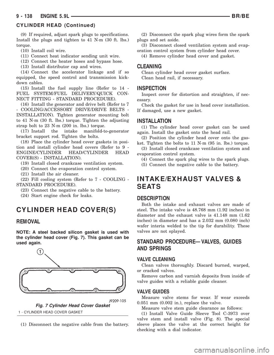
CYLINDER HEAD COVER(S)
REMOVAL
NOTE: A steel backed silicon gasket is used with
the cylinder head cover (Fig. 7). This gasket can be
used again.
(1) Disconnect the negative cable from the battery.(2) Disconnect the spark plug wires form the spark
plugs and set aside.
(3) Disconnect closed ventilation system and evap-
oration control system from cylinder head cover.
(4) Remove cylinder head cover and gasket.
CLEANING
Clean cylinder head cover gasket surface.
Clean head rail, if necessary.
INSPECTION
Inspect cover for distortion and straighten, if nec-
essary.
Check the gasket for use in head cover installation.
If damaged, use a new gasket.
INSTALLATION
(1) The cylinder head cover gasket can be used
again. Install the gasket onto the head rail.
(2) Position the cylinder head cover onto the gas-
ket. Tighten the bolts to 11 N´m (95 in. lbs.) torque.
(3) Install closed crankcase ventilation system and
evaporation control system.
(4)
Connect the spark plug wires to the spark plugs.
(5) Connect the negative cable to the battery.
INTAKE/EXHAUST VALVES &
SEATS
DESCRIPTION
Both the intake and exhaust valves are made of
steel. The intake valve is 48.768 mm (1.92 inches) in
diameter and the exhaust valve is 41.148 mm (1.62
inches) in diameter and has a 2.032 mm (0.080 inch)
wafer interia welded to the tip for durability. These
valves are not splayed.
STANDARD PROCEDUREÐVALVES, GUIDES
AND SPRINGS
VALVE CLEANING
Clean valves thoroughly. Discard burned, warped,
or cracked valves.
Remove carbon and varnish deposits from inside of
valve guides with a reliable guide cleaner.
VALVE GUIDES
Measure valve stems for wear. If wear exceeds
0.051 mm (0.002 in.), replace the valve.
Measure valve stem guide clearance as follows:
(1) Install Valve Guide Sleeve Tool C-3973 over
valve stem and install valve (Fig. 8). The special
sleeve places the valve at the correct height for
checking with a dial indicator.
Fig. 7 Cylinder Head Cover Gasket
1 - CYLINDER HEAD COVER GASKET
9 - 138 ENGINE 5.9LBR/BE
CYLINDER HEAD (Continued)
Page 1286 of 2889
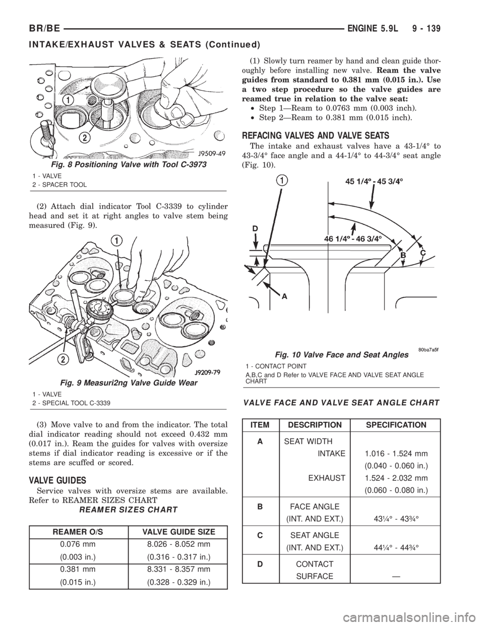
(2) Attach dial indicator Tool C-3339 to cylinder
head and set it at right angles to valve stem being
measured (Fig. 9).
(3) Move valve to and from the indicator. The total
dial indicator reading should not exceed 0.432 mm
(0.017 in.). Ream the guides for valves with oversize
stems if dial indicator reading is excessive or if the
stems are scuffed or scored.
VALVE GUIDES
Service valves with oversize stems are available.
Refer to REAMER SIZES CHART
REAMER SIZES CHART
REAMER O/S VALVE GUIDE SIZE
0.076 mm 8.026 - 8.052 mm
(0.003 in.) (0.316 - 0.317 in.)
0.381 mm 8.331 - 8.357 mm
(0.015 in.) (0.328 - 0.329 in.)(1)
Slowly turn reamer by hand and clean guide thor-
oughly before installing new valve.Ream the valve
guides from standard to 0.381 mm (0.015 in.). Use
a two step procedure so the valve guides are
reamed true in relation to the valve seat:
²Step 1ÐReam to 0.0763 mm (0.003 inch).
²Step 2ÐReam to 0.381 mm (0.015 inch).
REFACING VALVES AND VALVE SEATS
The intake and exhaust valves have a 43-1/4É to
43-3/4É face angle and a 44-1/4É to 44-3/4É seat angle
(Fig. 10).
VALVE FACE AND VALVE SEAT ANGLE CHART
ITEM DESCRIPTION SPECIFICATION
ASEAT WIDTH
INTAKE 1.016 - 1.524 mm
(0.040 - 0.060 in.)
EXHAUST 1.524 - 2.032 mm
(0.060 - 0.080 in.)
BFACE ANGLE
(INT. AND EXT.) 43òÉ - 43ôÉ
CSEAT ANGLE
(INT. AND EXT.) 44òÉ - 44ôÉ
DCONTACT
SURFACE Ð
Fig. 8 Positioning Valve with Tool C-3973
1 - VALVE
2 - SPACER TOOL
Fig. 9 Measuri2ng Valve Guide Wear
1 - VALVE
2 - SPECIAL TOOL C-3339
Fig. 10 Valve Face and Seat Angles
1 - CONTACT POINT
A,B,C and D Refer to VALVE FACE AND VALVE SEAT ANGLE
CHART
BR/BEENGINE 5.9L 9 - 139
INTAKE/EXHAUST VALVES & SEATS (Continued)
Page 1287 of 2889
VALVES
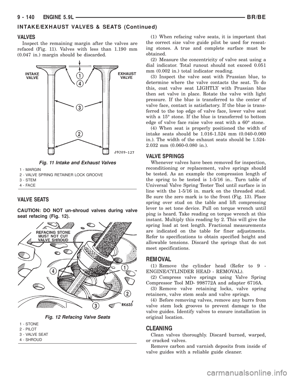
Inspect the remaining margin after the valves are
refaced (Fig. 11). Valves with less than 1.190 mm
(0.047 in.) margin should be discarded.
VALVE SEATS
CAUTION: DO NOT un-shroud valves during valve
seat refacing (Fig. 12).(1) When refacing valve seats, it is important that
the correct size valve guide pilot be used for reseat-
ing stones. A true and complete surface must be
obtained.
(2) Measure the concentricity of valve seat using a
dial indicator. Total runout should not exceed 0.051
mm (0.002 in.) total indicator reading.
(3) Inspect the valve seat with Prussian blue, to
determine where the valve contacts the seat. To do
this, coat valve seat LIGHTLY with Prussian blue
then set valve in place. Rotate the valve with light
pressure. If the blue is transferred to the center of
valve face, contact is satisfactory. If the blue is trans-
ferred to the top edge of valve face, lower valve seat
with a 15É stone. If the blue is transferred to bottom
edge of valve face raise valve seat with a 60É stone.
(4) When seat is properly positioned the width of
intake seats should be 1.016-1.524 mm (0.040-0.060
in.). The width of the exhaust seats should be 1.524-
2.032 mm (0.060-0.080 in.).
VALVE SPRINGS
Whenever valves have been removed for inspection,
reconditioning or replacement, valve springs should
be tested. As an example the compression length of
the spring to be tested is 1-5/16 in.. Turn table of
Universal Valve Spring Tester Tool until surface is in
line with the 1-5/16 in. mark on the threaded stud.
Be sure the zero mark is to the front (Fig. 13). Place
spring over stud on the table and lift compressing
lever to set tone device. Pull on torque wrench until
ping is heard. Take reading on torque wrench at this
instant. Multiply this reading by 2. This will give the
spring load at test length. Fractional measurements
are indicated on the table for finer adjustments.
Refer to specifications to obtain specified height and
allowable tensions. Discard the springs that do not
meet specifications.
REMOVAL
(1) Remove the cylinder head (Refer to 9 -
ENGINE/CYLINDER HEAD - REMOVAL).
(2) Compress valve springs using Valve Spring
Compressor Tool MD- 998772A and adapter 6716A.
(3) Remove valve retaining locks, valve spring
retainers, valve stem seals and valve springs.
(4) Before removing valves, remove any burrs from
valve stem lock grooves to prevent damage to the
valve guides. Identify valves to ensure installation in
original location.
CLEANING
Clean valves thoroughly. Discard burned, warped,
or cracked valves.
Remove carbon and varnish deposits from inside of
valve guides with a reliable guide cleaner.
Fig. 11 Intake and Exhaust Valves
1 - MARGIN
2 - VALVE SPRING RETAINER LOCK GROOVE
3 - STEM
4-FACE
Fig. 12 Refacing Valve Seats
1-STONE
2 - PILOT
3 - VALVE SEAT
4 - SHROUD
9 - 140 ENGINE 5.9LBR/BE
INTAKE/EXHAUST VALVES & SEATS (Continued)
Page 1288 of 2889
INSPECTION
Measure valve stems for wear. If wear exceeds
0.051 mm (0.002 in.), replace the valve.
Measure valve stem guide clearance as follows:
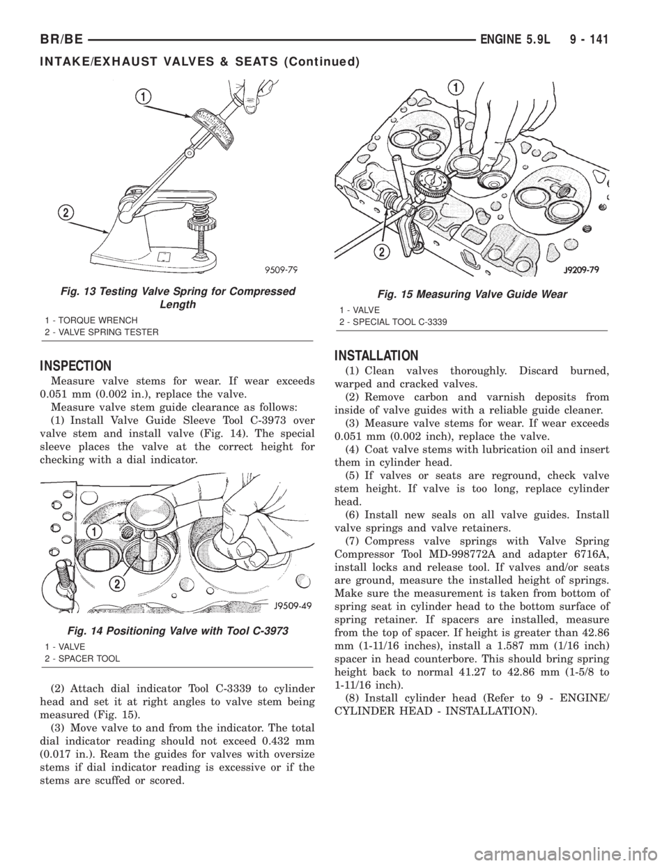
(1) Install Valve Guide Sleeve Tool C-3973 over
valve stem and install valve (Fig. 14). The special
sleeve places the valve at the correct height for
checking with a dial indicator.
(2) Attach dial indicator Tool C-3339 to cylinder
head and set it at right angles to valve stem being
measured (Fig. 15).
(3) Move valve to and from the indicator. The total
dial indicator reading should not exceed 0.432 mm
(0.017 in.). Ream the guides for valves with oversize
stems if dial indicator reading is excessive or if the
stems are scuffed or scored.
INSTALLATION
(1) Clean valves thoroughly. Discard burned,
warped and cracked valves.
(2) Remove carbon and varnish deposits from
inside of valve guides with a reliable guide cleaner.
(3) Measure valve stems for wear. If wear exceeds
0.051 mm (0.002 inch), replace the valve.
(4) Coat valve stems with lubrication oil and insert
them in cylinder head.
(5) If valves or seats are reground, check valve
stem height. If valve is too long, replace cylinder
head.
(6) Install new seals on all valve guides. Install
valve springs and valve retainers.
(7) Compress valve springs with Valve Spring
Compressor Tool MD-998772A and adapter 6716A,
install locks and release tool. If valves and/or seats
are ground, measure the installed height of springs.
Make sure the measurement is taken from bottom of
spring seat in cylinder head to the bottom surface of
spring retainer. If spacers are installed, measure
from the top of spacer. If height is greater than 42.86
mm (1-11/16 inches), install a 1.587 mm (1/16 inch)
spacer in head counterbore. This should bring spring
height back to normal 41.27 to 42.86 mm (1-5/8 to
1-11/16 inch).
(8) Install cylinder head (Refer to 9 - ENGINE/
CYLINDER HEAD - INSTALLATION).
Fig. 13 Testing Valve Spring for Compressed
Length
1 - TORQUE WRENCH
2 - VALVE SPRING TESTER
Fig. 14 Positioning Valve with Tool C-3973
1 - VALVE
2 - SPACER TOOL
Fig. 15 Measuring Valve Guide Wear
1 - VALVE
2 - SPECIAL TOOL C-3339
BR/BEENGINE 5.9L 9 - 141
INTAKE/EXHAUST VALVES & SEATS (Continued)
Page 1289 of 2889
ROCKER ARM / ADJUSTER
ASSY
REMOVAL
(1) Remove cylinder head cover and gasket (Refer
to 9 - ENGINE/CYLINDER HEAD/CYLINDER
HEAD COVER(S) - REMOVAL).
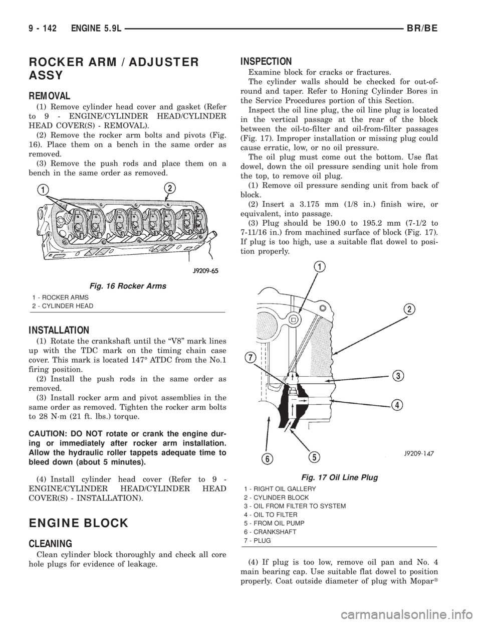
(2) Remove the rocker arm bolts and pivots (Fig.
16). Place them on a bench in the same order as
removed.
(3) Remove the push rods and place them on a
bench in the same order as removed.
INSTALLATION
(1) Rotate the crankshaft until the ªV8º mark lines
up with the TDC mark on the timing chain case
cover. This mark is located 147É ATDC from the No.1
firing position.
(2) Install the push rods in the same order as
removed.
(3) Install rocker arm and pivot assemblies in the
same order as removed. Tighten the rocker arm bolts
to 28 N´m (21 ft. lbs.) torque.
CAUTION: DO NOT rotate or crank the engine dur-
ing or immediately after rocker arm installation.
Allow the hydraulic roller tappets adequate time to
bleed down (about 5 minutes).
(4) Install cylinder head cover (Refer to 9 -
ENGINE/CYLINDER HEAD/CYLINDER HEAD
COVER(S) - INSTALLATION).
ENGINE BLOCK
CLEANING
Clean cylinder block thoroughly and check all core
hole plugs for evidence of leakage.
INSPECTION
Examine block for cracks or fractures.
The cylinder walls should be checked for out-of-
round and taper. Refer to Honing Cylinder Bores in
the Service Procedures portion of this Section.
Inspect the oil line plug, the oil line plug is located
in the vertical passage at the rear of the block
between the oil-to-filter and oil-from-filter passages
(Fig. 17). Improper installation or missing plug could
cause erratic, low, or no oil pressure.
The oil plug must come out the bottom. Use flat
dowel, down the oil pressure sending unit hole from
the top, to remove oil plug.
(1) Remove oil pressure sending unit from back of
block.
(2) Insert a 3.175 mm (1/8 in.) finish wire, or
equivalent, into passage.
(3) Plug should be 190.0 to 195.2 mm (7-1/2 to
7-11/16 in.) from machined surface of block (Fig. 17).
If plug is too high, use a suitable flat dowel to posi-
tion properly.
(4) If plug is too low, remove oil pan and No. 4
main bearing cap. Use suitable flat dowel to position
properly. Coat outside diameter of plug with Mopart
Fig. 16 Rocker Arms
1 - ROCKER ARMS
2 - CYLINDER HEAD
Fig. 17 Oil Line Plug
1 - RIGHT OIL GALLERY
2 - CYLINDER BLOCK
3 - OIL FROM FILTER TO SYSTEM
4 - OIL TO FILTER
5 - FROM OIL PUMP
6 - CRANKSHAFT
7 - PLUG
9 - 142 ENGINE 5.9LBR/BE
Page 1290 of 2889
Stud and Bearing Mount Adhesive. Plug should be
54.0 to 57.7 mm (2-1/8 to 2-5/16 in.) from bottom of
the block.
CAMSHAFT & BEARINGS (IN
BLOCK)
REMOVALÐCAMSHAFT BEARINGS
NOTE: This procedure requires that the engine is
removed from the vehicle.
(1) With engine completely disassembled, drive out
rear cam bearing core plug.
(2) Install proper size adapters and horseshoe
washers (part of Camshaft Bearing Remover/Installer
Tool C-3132-A) at back of each bearing shell. Drive
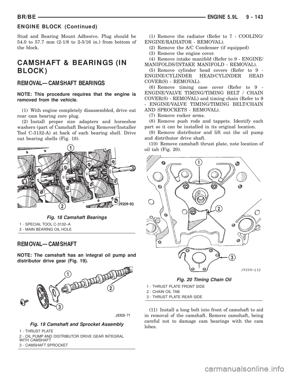
out bearing shells (Fig. 18).
REMOVALÐCAMSHAFT
NOTE: The camshaft has an integral oil pump and
distributor drive gear (Fig. 19).(1) Remove the radiator (Refer to 7 - COOLING/
ENGINE/RADIATOR - REMOVAL).
(2) Remove the A/C Condenser (if equipped)
(3) Remove the engine cover.
(4) Remove intake manifold (Refer to 9 - ENGINE/
MANIFOLDS/INTAKE MANIFOLD - REMOVAL).
(5) Remove cylinder head covers (Refer to 9 -
ENGINE/CYLINDER HEAD/CYLINDER HEAD
COVER(S) - REMOVAL).
(6) Remove timing case cover (Refer to 9 -
ENGINE/VALVE TIMING/TIMING BELT / CHAIN
COVER(S) - REMOVAL) and timing chain (Refer to 9
- ENGINE/VALVE TIMING/TIMING BELT/CHAIN
AND SPROCKETS - REMOVAL).
(7) Remove rocker arms.
(8) Remove push rods and tappets. Identify each
part so it can be installed in its original location.
(9) Remove distributor and lift out the oil pump
and distributor drive shaft.
(10) Remove camshaft thrust plate, note location of
oil tab (Fig. 20).
(11) Install a long bolt into front of camshaft to aid
in removal of the camshaft. Remove camshaft, being
careful not to damage cam bearings with the cam
lobes.
Fig. 18 Camshaft Bearings
1 - SPECIAL TOOL C-3132±A
2 - MAIN BEARING OIL HOLE
Fig. 19 Camshaft and Sprocket Assembly
1 - THRUST PLATE
2 - OIL PUMP AND DISTRIBUTOR DRIVE GEAR INTEGRAL
WITH CAMSHAFT
3 - CAMSHAFT SPROCKET
Fig. 20 Timing Chain Oil
1 - THRUST PLATE FRONT SIDE
2 - CHAIN OIL TAB
3 - THRUST PLATE REAR SIDE
BR/BEENGINE 5.9L 9 - 143
ENGINE BLOCK (Continued)