DODGE RAM 2001 Service Repair Manual
Manufacturer: DODGE, Model Year: 2001, Model line: RAM, Model: DODGE RAM 2001Pages: 2889, PDF Size: 68.07 MB
Page 1571 of 2889
If a Diagnostic Trouble Code (DTC) has been stored
for ªdecreased engine performance due to high injec-
tion pump fuel temperatureº, the overflow valve may
be stuck in closed position.
DIAGNOSIS AND TESTING - OVERFLOW VALVE
Fuel volume from the fuel transfer (lift) pump will
always provide more fuel than the fuel injection
pump requires. The overflow valve (a check valve) is
used to route excess fuel through the fuel return line
and back to the fuel tank. Approximately 70% of sup-
plied fuel is returned to the fuel tank. The valve is
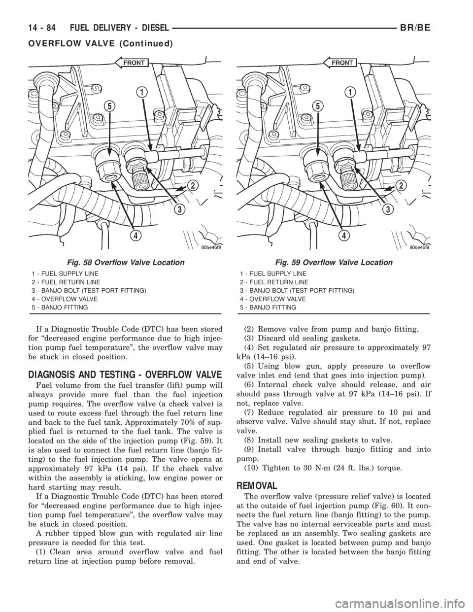
located on the side of the injection pump (Fig. 59). It
is also used to connect the fuel return line (banjo fit-
ting) to the fuel injection pump. The valve opens at
approximately 97 kPa (14 psi). If the check valve
within the assembly is sticking, low engine power or
hard starting may result.
If a Diagnostic Trouble Code (DTC) has been stored
for ªdecreased engine performance due to high injec-
tion pump fuel temperatureº, the overflow valve may
be stuck in closed position.
A rubber tipped blow gun with regulated air line
pressure is needed for this test.
(1) Clean area around overflow valve and fuel
return line at injection pump before removal.(2) Remove valve from pump and banjo fitting.
(3) Discard old sealing gaskets.
(4) Set regulated air pressure to approximately 97
kPa (14±16 psi).
(5) Using blow gun, apply pressure to overflow
valve inlet end (end that goes into injection pump).
(6) Internal check valve should release, and air
should pass through valve at 97 kPa (14±16 psi). If
not, replace valve.
(7) Reduce regulated air pressure to 10 psi and
observe valve. Valve should stay shut. If not, replace
valve.
(8) Install new sealing gaskets to valve.
(9) Install valve through banjo fitting and into
pump.
(10) Tighten to 30 N´m (24 ft. lbs.) torque.
REMOVAL
The overflow valve (pressure relief valve) is located
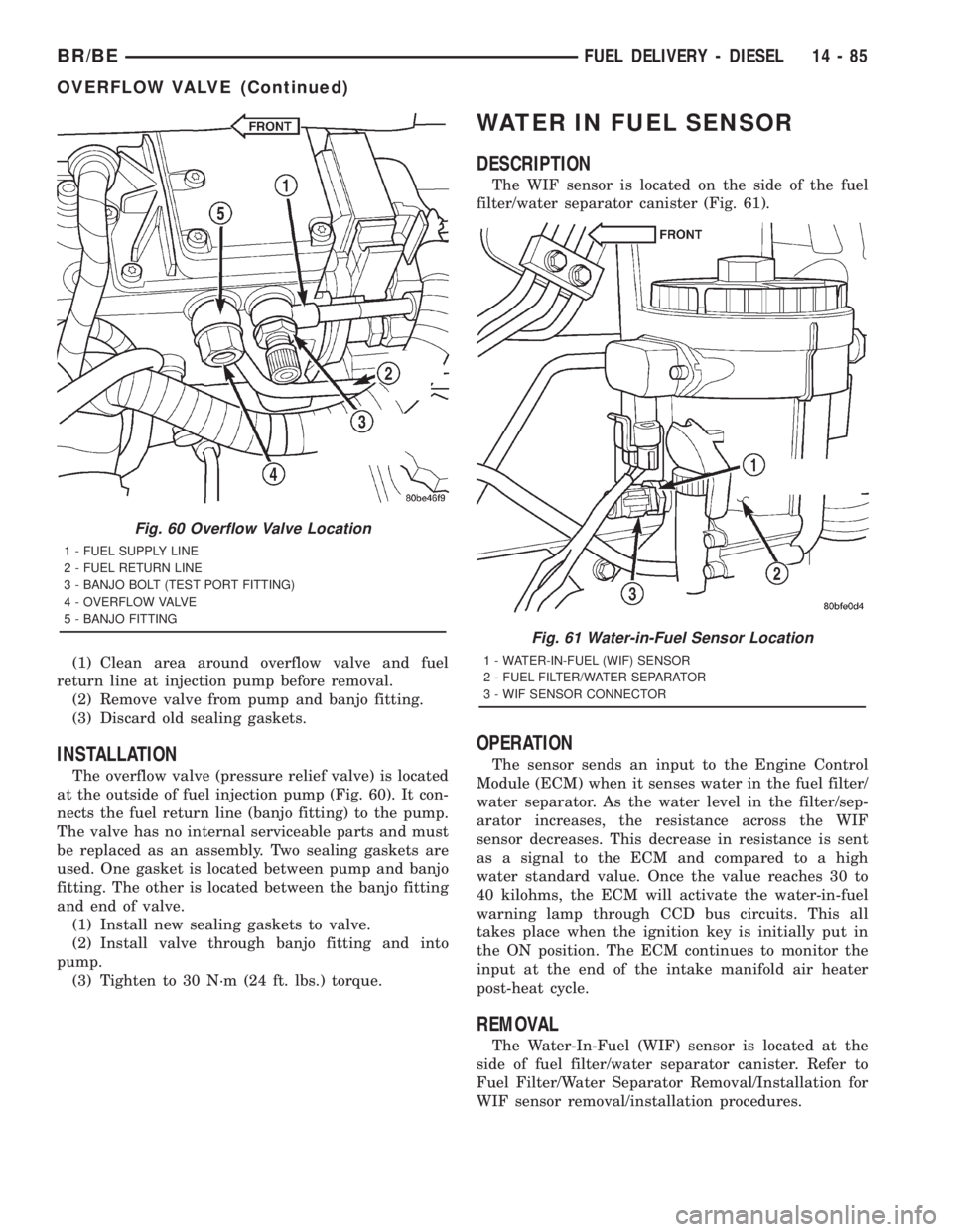
at the outside of fuel injection pump (Fig. 60). It con-
nects the fuel return line (banjo fitting) to the pump.
The valve has no internal serviceable parts and must
be replaced as an assembly. Two sealing gaskets are
used. One gasket is located between pump and banjo
fitting. The other is located between the banjo fitting
and end of valve.
Fig. 58 Overflow Valve Location
1 - FUEL SUPPLY LINE
2 - FUEL RETURN LINE
3 - BANJO BOLT (TEST PORT FITTING)
4 - OVERFLOW VALVE
5 - BANJO FITTING
Fig. 59 Overflow Valve Location
1 - FUEL SUPPLY LINE
2 - FUEL RETURN LINE
3 - BANJO BOLT (TEST PORT FITTING)
4 - OVERFLOW VALVE
5 - BANJO FITTING
14 - 84 FUEL DELIVERY - DIESELBR/BE
OVERFLOW VALVE (Continued)
Page 1572 of 2889
(1) Clean area around overflow valve and fuel
return line at injection pump before removal.
(2) Remove valve from pump and banjo fitting.
(3) Discard old sealing gaskets.
INSTALLATION
The overflow valve (pressure relief valve) is located
at the outside of fuel injection pump (Fig. 60). It con-
nects the fuel return line (banjo fitting) to the pump.
The valve has no internal serviceable parts and must
be replaced as an assembly. Two sealing gaskets are
used. One gasket is located between pump and banjo
fitting. The other is located between the banjo fitting
and end of valve.
(1) Install new sealing gaskets to valve.
(2) Install valve through banjo fitting and into
pump.
(3) Tighten to 30 N´m (24 ft. lbs.) torque.
WATER IN FUEL SENSOR
DESCRIPTION
The WIF sensor is located on the side of the fuel
filter/water separator canister (Fig. 61).
OPERATION
The sensor sends an input to the Engine Control
Module (ECM) when it senses water in the fuel filter/
water separator. As the water level in the filter/sep-
arator increases, the resistance across the WIF
sensor decreases. This decrease in resistance is sent
as a signal to the ECM and compared to a high
water standard value. Once the value reaches 30 to
40 kilohms, the ECM will activate the water-in-fuel
warning lamp through CCD bus circuits. This all
takes place when the ignition key is initially put in
the ON position. The ECM continues to monitor the
input at the end of the intake manifold air heater
post-heat cycle.
REMOVAL
The Water-In-Fuel (WIF) sensor is located at the
side of fuel filter/water separator canister. Refer to
Fuel Filter/Water Separator Removal/Installation for
WIF sensor removal/installation procedures.
Fig. 60 Overflow Valve Location
1 - FUEL SUPPLY LINE
2 - FUEL RETURN LINE
3 - BANJO BOLT (TEST PORT FITTING)
4 - OVERFLOW VALVE
5 - BANJO FITTING
Fig. 61 Water-in-Fuel Sensor Location
1 - WATER-IN-FUEL (WIF) SENSOR
2 - FUEL FILTER/WATER SEPARATOR
3 - WIF SENSOR CONNECTOR
BR/BEFUEL DELIVERY - DIESEL 14 - 85
OVERFLOW VALVE (Continued)
Page 1573 of 2889
FUEL DRAIN MANIFOLD
DESCRIPTION
The fuel drain manifold is actually a rifled passage
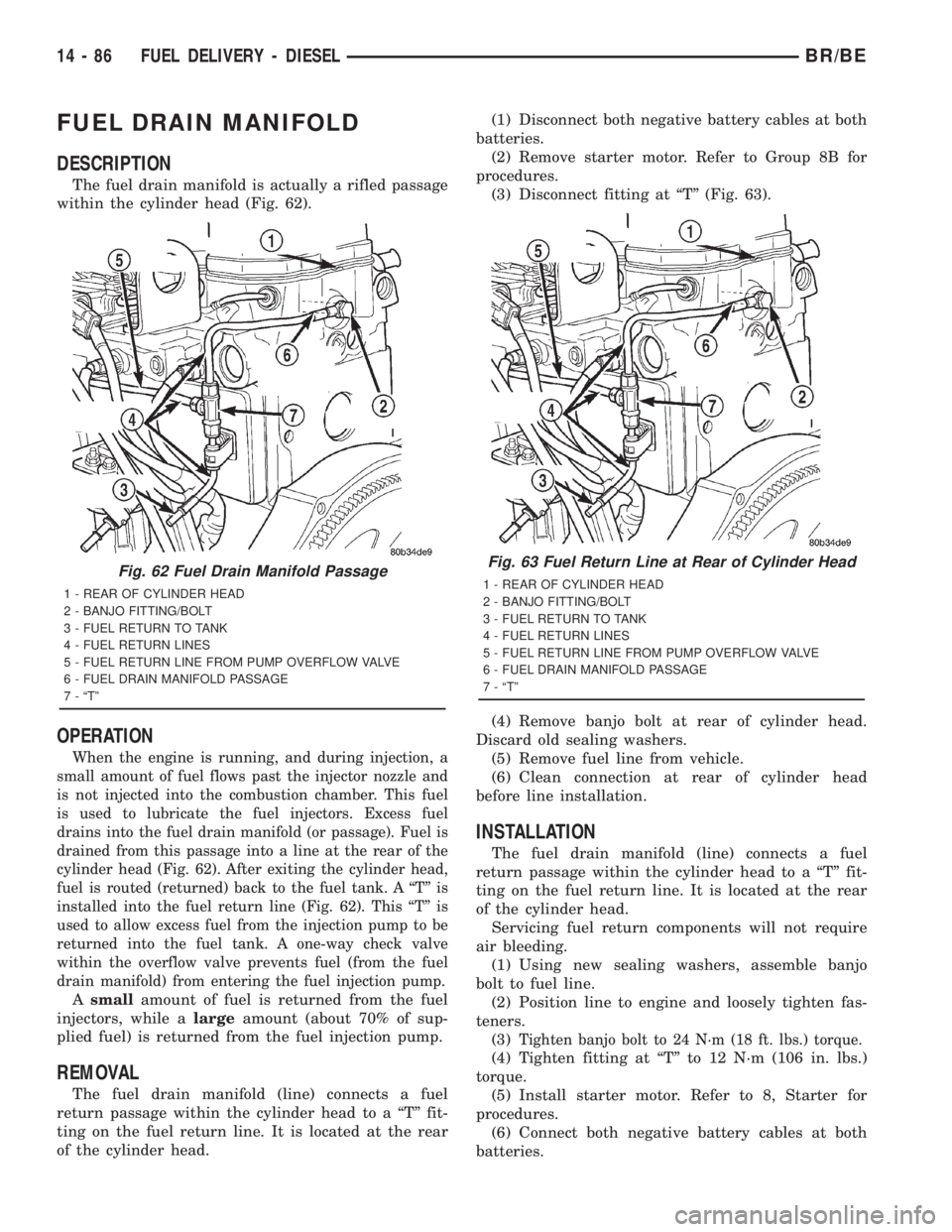
within the cylinder head (Fig. 62).
OPERATION
When the engine is running, and during injection, a
small amount of fuel flows past the injector nozzle and
is not injected into the combustion chamber. This fuel
is used to lubricate the fuel injectors. Excess fuel
drains into the fuel drain manifold (or passage). Fuel is
drained from this passage into a line at the rear of the
cylinder head (Fig. 62). After exiting the cylinder head,
fuel is routed (returned) back to the fuel tank. A ªTº is
installed into the fuel return line (Fig. 62). This ªTº is
used to allow excess fuel from the injection pump to be
returned into the fuel tank. A one-way check valve
within the overflow valve prevents fuel (from the fuel
drain manifold) from entering the fuel injection pump.
Asmallamount of fuel is returned from the fuel
injectors, while alargeamount (about 70% of sup-
plied fuel) is returned from the fuel injection pump.
REMOVAL
The fuel drain manifold (line) connects a fuel
return passage within the cylinder head to a ªTº fit-
ting on the fuel return line. It is located at the rear
of the cylinder head.(1) Disconnect both negative battery cables at both
batteries.
(2) Remove starter motor. Refer to Group 8B for
procedures.
(3) Disconnect fitting at ªTº (Fig. 63).
(4) Remove banjo bolt at rear of cylinder head.
Discard old sealing washers.
(5) Remove fuel line from vehicle.
(6) Clean connection at rear of cylinder head
before line installation.
INSTALLATION
The fuel drain manifold (line) connects a fuel
return passage within the cylinder head to a ªTº fit-
ting on the fuel return line. It is located at the rear
of the cylinder head.
Servicing fuel return components will not require
air bleeding.
(1) Using new sealing washers, assemble banjo
bolt to fuel line.
(2) Position line to engine and loosely tighten fas-
teners.
(3)
Tighten banjo bolt to 24 N´m (18 ft. lbs.) torque.
(4) Tighten fitting at ªTº to 12 N´m (106 in. lbs.)
torque.
(5) Install starter motor. Refer to 8, Starter for
procedures.
(6) Connect both negative battery cables at both
batteries.
Fig. 62 Fuel Drain Manifold Passage
1 - REAR OF CYLINDER HEAD
2 - BANJO FITTING/BOLT
3 - FUEL RETURN TO TANK
4 - FUEL RETURN LINES
5 - FUEL RETURN LINE FROM PUMP OVERFLOW VALVE
6 - FUEL DRAIN MANIFOLD PASSAGE
7 - ªTº
Fig. 63 Fuel Return Line at Rear of Cylinder Head
1 - REAR OF CYLINDER HEAD
2 - BANJO FITTING/BOLT
3 - FUEL RETURN TO TANK
4 - FUEL RETURN LINES
5 - FUEL RETURN LINE FROM PUMP OVERFLOW VALVE
6 - FUEL DRAIN MANIFOLD PASSAGE
7 - ªTº
14 - 86 FUEL DELIVERY - DIESELBR/BE
Page 1574 of 2889
FUEL INJECTION - DIESEL
TABLE OF CONTENTS
page page
FUEL INJECTION - DIESEL
DESCRIPTION...........................87
DIAGNOSIS AND TESTING.................89
BOOST PRESSURE.....................89
SPECIFICATIONS........................90
ACCELERATOR PEDAL POSITION SENSOR
DESCRIPTION...........................91
OPERATION.............................91
REMOVAL..............................91
INSTALLATION...........................93
FUEL INJECTOR
DESCRIPTION...........................93
OPERATION.............................94
DIAGNOSIS AND TESTING.................95
FUEL INJECTOR TEST...................95
REMOVAL..............................96
INSTALLATION...........................98
FUEL INJECTION PUMP RELAY
DESCRIPTION...........................99
OPERATION.............................99
FUEL TEMPERATURE SENSOR
DESCRIPTION...........................99
OPERATION............................100
INTAKE AIR HEATER
DESCRIPTION..........................100OPERATION............................100
REMOVAL.............................100
INSTALLATION..........................101
INTAKE AIR HEATER RELAY
DESCRIPTION..........................101
OPERATION............................102
REMOVAL.............................102
INSTALLATION..........................102
INTAKE AIR TEMPERATURE SENSOR
DESCRIPTION..........................102
OPERATION............................102
REMOVAL.............................103
INSTALLATION..........................103
MAP SENSOR
DESCRIPTION..........................103
OPERATION............................103
REMOVAL.............................104
INSTALLATION..........................104
PTO SWITCH
DESCRIPTION..........................104
THROTTLE CONTROL CABLE
REMOVAL.............................104
INSTALLATION..........................105
FUEL INJECTION - DIESEL
DESCRIPTION - DIESEL FUEL INJECTION
SYSTEM
The Engine Control Module (ECM) and Fuel Injec-
tion Pump Control Module (FPCM) are used prima-
rily for fuel system control. The ECM is a separate
replaceable component, while the FPCM is internal
to the fuel injection pump and is a non-serviceable
part. The ECM and FPCM are interconnected (wired
together) for fuel injection control.The Powertrain Control Module (PCM) is used to
regulate or control the A/C, charging and speed con-
trol systems. It is also used to partially control cer-
tain electronic automatic transmission components.
The PCM also has control over certain instrument
panel components.
Refer to either Powertrain Control Module (PCM)
or Engine Control Module (ECM) for additional infor-
mation. Refer to (Fig. 1) for a partial list of fuel sys-
tem components.
BR/BEFUEL INJECTION - DIESEL 14 - 87
Page 1575 of 2889
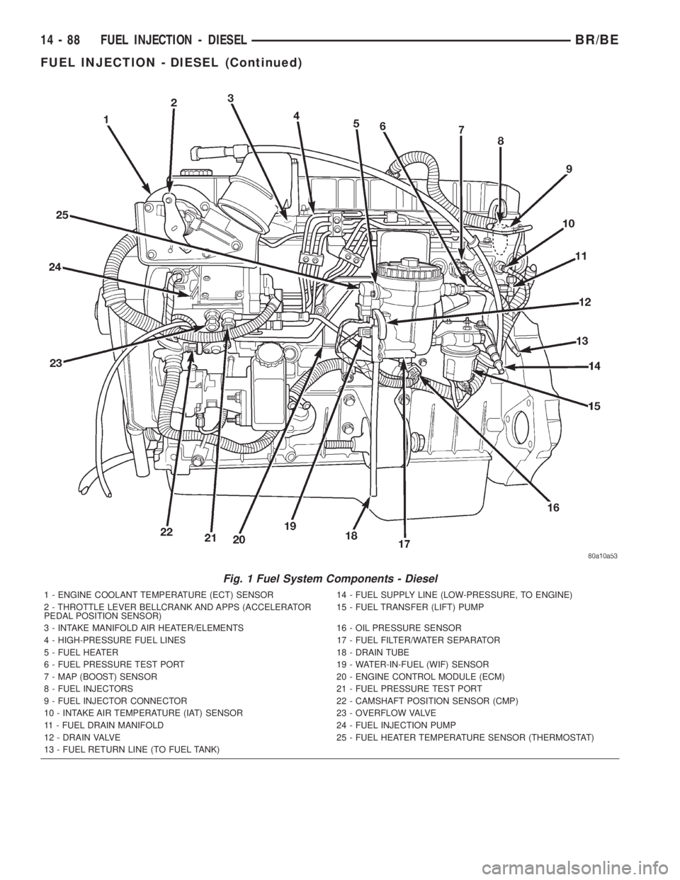
Fig. 1 Fuel System Components - Diesel
1 - ENGINE COOLANT TEMPERATURE (ECT) SENSOR 14 - FUEL SUPPLY LINE (LOW-PRESSURE, TO ENGINE)
2 - THROTTLE LEVER BELLCRANK AND APPS (ACCELERATOR
PEDAL POSITION SENSOR)15 - FUEL TRANSFER (LIFT) PUMP
3 - INTAKE MANIFOLD AIR HEATER/ELEMENTS 16 - OIL PRESSURE SENSOR
4 - HIGH-PRESSURE FUEL LINES 17 - FUEL FILTER/WATER SEPARATOR
5 - FUEL HEATER 18 - DRAIN TUBE
6 - FUEL PRESSURE TEST PORT 19 - WATER-IN-FUEL (WIF) SENSOR
7 - MAP (BOOST) SENSOR 20 - ENGINE CONTROL MODULE (ECM)
8 - FUEL INJECTORS 21 - FUEL PRESSURE TEST PORT
9 - FUEL INJECTOR CONNECTOR 22 - CAMSHAFT POSITION SENSOR (CMP)
10 - INTAKE AIR TEMPERATURE (IAT) SENSOR 23 - OVERFLOW VALVE
11 - FUEL DRAIN MANIFOLD 24 - FUEL INJECTION PUMP
12 - DRAIN VALVE 25 - FUEL HEATER TEMPERATURE SENSOR (THERMOSTAT)
13 - FUEL RETURN LINE (TO FUEL TANK)
14 - 88 FUEL INJECTION - DIESELBR/BE
FUEL INJECTION - DIESEL (Continued)
Page 1576 of 2889
DIAGNOSIS AND TESTING - BOOST PRESSURE
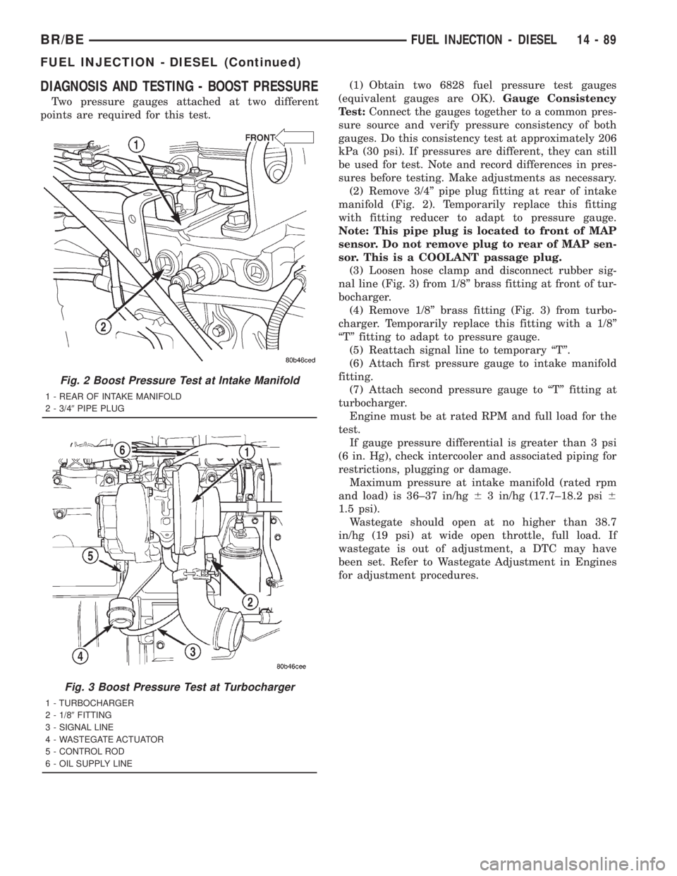
Two pressure gauges attached at two different
points are required for this test.(1) Obtain two 6828 fuel pressure test gauges
(equivalent gauges are OK).Gauge Consistency
Test:Connect the gauges together to a common pres-
sure source and verify pressure consistency of both
gauges. Do this consistency test at approximately 206
kPa (30 psi). If pressures are different, they can still
be used for test. Note and record differences in pres-
sures before testing. Make adjustments as necessary.
(2) Remove 3/4º pipe plug fitting at rear of intake
manifold (Fig. 2). Temporarily replace this fitting
with fitting reducer to adapt to pressure gauge.
Note: This pipe plug is located to front of MAP
sensor. Do not remove plug to rear of MAP sen-
sor. This is a COOLANT passage plug.
(3) Loosen hose clamp and disconnect rubber sig-
nal line (Fig. 3) from 1/8º brass fitting at front of tur-
bocharger.
(4) Remove 1/8º brass fitting (Fig. 3) from turbo-
charger. Temporarily replace this fitting with a 1/8º
ªTº fitting to adapt to pressure gauge.
(5) Reattach signal line to temporary ªTº.
(6) Attach first pressure gauge to intake manifold
fitting.
(7) Attach second pressure gauge to ªTº fitting at
turbocharger.
Engine must be at rated RPM and full load for the
test.
If gauge pressure differential is greater than 3 psi
(6 in. Hg), check intercooler and associated piping for
restrictions, plugging or damage.
Maximum pressure at intake manifold (rated rpm
and load) is 36±37 in/hg63 in/hg (17.7±18.2 psi6
1.5 psi).
Wastegate should open at no higher than 38.7
in/hg (19 psi) at wide open throttle, full load. If
wastegate is out of adjustment, a DTC may have
been set. Refer to Wastegate Adjustment in Engines
for adjustment procedures.
Fig. 2 Boost Pressure Test at Intake Manifold
1 - REAR OF INTAKE MANIFOLD
2 - 3/49PIPE PLUG
Fig. 3 Boost Pressure Test at Turbocharger
1 - TURBOCHARGER
2 - 1/89FITTING
3 - SIGNAL LINE
4 - WASTEGATE ACTUATOR
5 - CONTROL ROD
6 - OIL SUPPLY LINE
BR/BEFUEL INJECTION - DIESEL 14 - 89
FUEL INJECTION - DIESEL (Continued)
Page 1577 of 2889
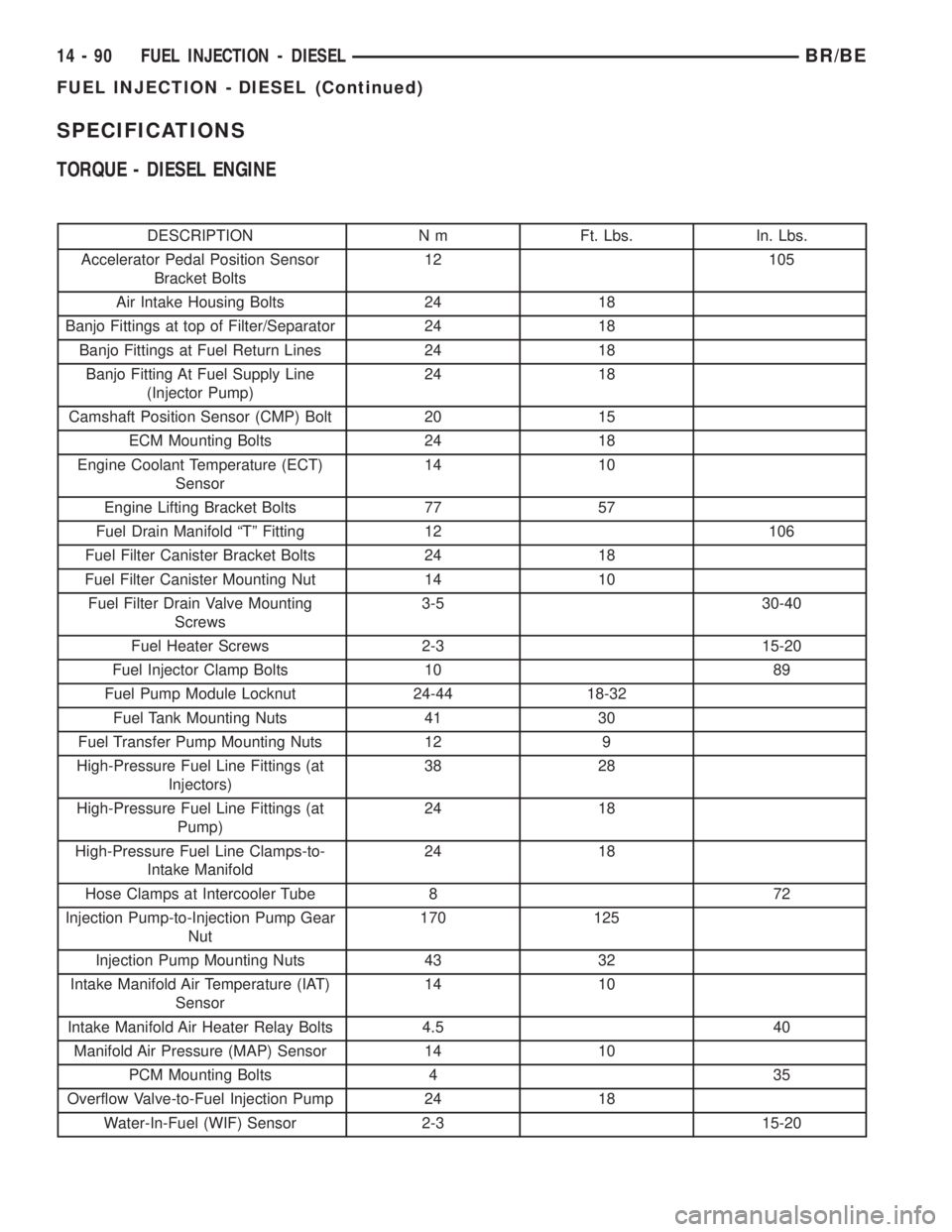
SPECIFICATIONS
TORQUE - DIESEL ENGINE
DESCRIPTION N m Ft. Lbs. In. Lbs.
Accelerator Pedal Position Sensor
Bracket Bolts12 105
Air Intake Housing Bolts 24 18
Banjo Fittings at top of Filter/Separator 24 18
Banjo Fittings at Fuel Return Lines 24 18
Banjo Fitting At Fuel Supply Line
(Injector Pump)24 18
Camshaft Position Sensor (CMP) Bolt 20 15
ECM Mounting Bolts 24 18
Engine Coolant Temperature (ECT)
Sensor14 10
Engine Lifting Bracket Bolts 77 57
Fuel Drain Manifold ªTº Fitting 12 106
Fuel Filter Canister Bracket Bolts 24 18
Fuel Filter Canister Mounting Nut 14 10
Fuel Filter Drain Valve Mounting
Screws3-5 30-40
Fuel Heater Screws 2-3 15-20
Fuel Injector Clamp Bolts 10 89
Fuel Pump Module Locknut 24-44 18-32
Fuel Tank Mounting Nuts 41 30
Fuel Transfer Pump Mounting Nuts 12 9
High-Pressure Fuel Line Fittings (at
Injectors)38 28
High-Pressure Fuel Line Fittings (at
Pump)24 18
High-Pressure Fuel Line Clamps-to-
Intake Manifold24 18
Hose Clamps at Intercooler Tube 8 72
Injection Pump-to-Injection Pump Gear
Nut170 125
Injection Pump Mounting Nuts 43 32
Intake Manifold Air Temperature (IAT)
Sensor14 10
Intake Manifold Air Heater Relay Bolts 4.5 40
Manifold Air Pressure (MAP) Sensor 14 10
PCM Mounting Bolts 4 35
Overflow Valve-to-Fuel Injection Pump 24 18
Water-In-Fuel (WIF) Sensor 2-3 15-20
14 - 90 FUEL INJECTION - DIESELBR/BE
FUEL INJECTION - DIESEL (Continued)
Page 1578 of 2889
ACCELERATOR PEDAL
POSITION SENSOR
DESCRIPTION
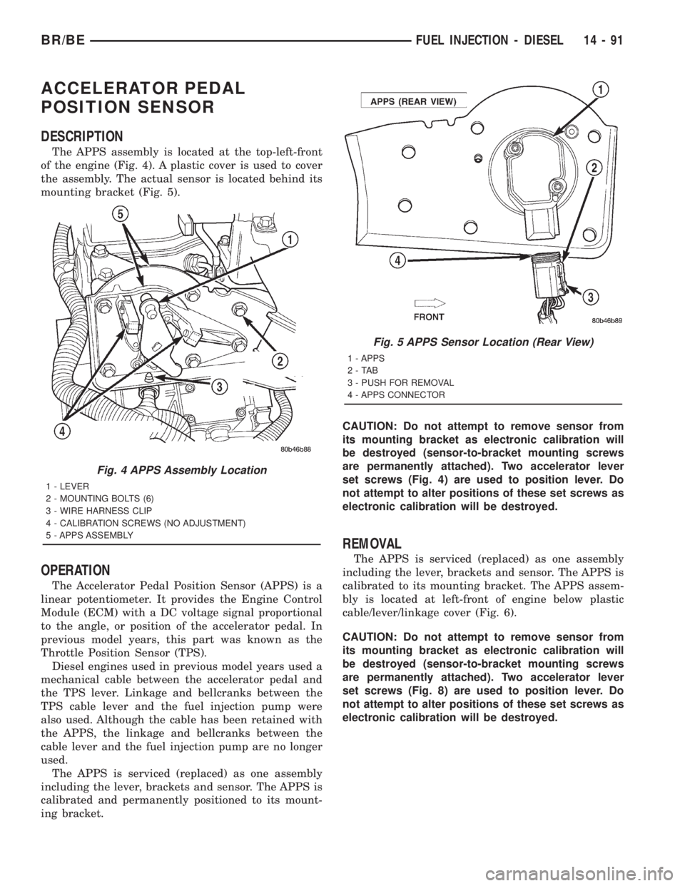
The APPS assembly is located at the top-left-front
of the engine (Fig. 4). A plastic cover is used to cover
the assembly. The actual sensor is located behind its
mounting bracket (Fig. 5).
OPERATION
The Accelerator Pedal Position Sensor (APPS) is a
linear potentiometer. It provides the Engine Control
Module (ECM) with a DC voltage signal proportional
to the angle, or position of the accelerator pedal. In
previous model years, this part was known as the
Throttle Position Sensor (TPS).
Diesel engines used in previous model years used a
mechanical cable between the accelerator pedal and
the TPS lever. Linkage and bellcranks between the
TPS cable lever and the fuel injection pump were
also used. Although the cable has been retained with
the APPS, the linkage and bellcranks between the
cable lever and the fuel injection pump are no longer
used.
The APPS is serviced (replaced) as one assembly
including the lever, brackets and sensor. The APPS is
calibrated and permanently positioned to its mount-
ing bracket.CAUTION: Do not attempt to remove sensor from
its mounting bracket as electronic calibration will
be destroyed (sensor-to-bracket mounting screws
are permanently attached). Two accelerator lever
set screws (Fig. 4) are used to position lever. Do
not attempt to alter positions of these set screws as
electronic calibration will be destroyed.
REMOVAL
The APPS is serviced (replaced) as one assembly
including the lever, brackets and sensor. The APPS is
calibrated to its mounting bracket. The APPS assem-
bly is located at left-front of engine below plastic
cable/lever/linkage cover (Fig. 6).
CAUTION: Do not attempt to remove sensor from
its mounting bracket as electronic calibration will
be destroyed (sensor-to-bracket mounting screws
are permanently attached). Two accelerator lever
set screws (Fig. 8) are used to position lever. Do
not attempt to alter positions of these set screws as
electronic calibration will be destroyed.
Fig. 4 APPS Assembly Location
1 - LEVER
2 - MOUNTING BOLTS (6)
3 - WIRE HARNESS CLIP
4 - CALIBRATION SCREWS (NO ADJUSTMENT)
5 - APPS ASSEMBLY
Fig. 5 APPS Sensor Location (Rear View)
1 - APPS
2-TAB
3 - PUSH FOR REMOVAL
4 - APPS CONNECTOR
BR/BEFUEL INJECTION - DIESEL 14 - 91
Page 1579 of 2889
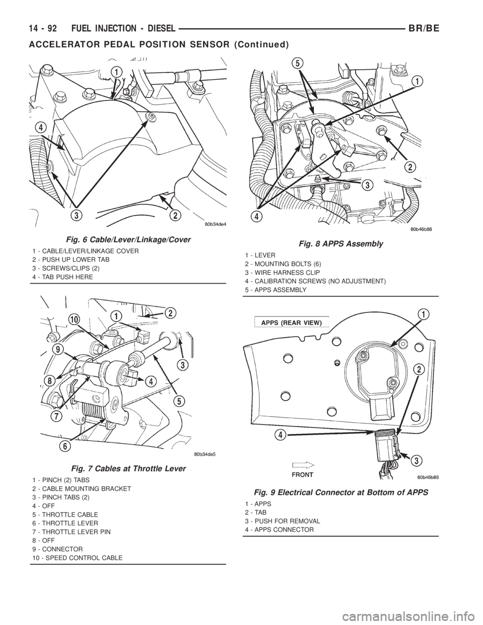
Fig. 6 Cable/Lever/Linkage/Cover
1 - CABLE/LEVER/LINKAGE COVER
2 - PUSH UP LOWER TAB
3 - SCREWS/CLIPS (2)
4 - TAB PUSH HERE
Fig. 7 Cables at Throttle Lever
1 - PINCH (2) TABS
2 - CABLE MOUNTING BRACKET
3 - PINCH TABS (2)
4 - OFF
5 - THROTTLE CABLE
6 - THROTTLE LEVER
7 - THROTTLE LEVER PIN
8 - OFF
9 - CONNECTOR
10 - SPEED CONTROL CABLE
Fig. 8 APPS Assembly
1 - LEVER
2 - MOUNTING BOLTS (6)
3 - WIRE HARNESS CLIP
4 - CALIBRATION SCREWS (NO ADJUSTMENT)
5 - APPS ASSEMBLY
Fig. 9 Electrical Connector at Bottom of APPS
1 - APPS
2-TAB
3 - PUSH FOR REMOVAL
4 - APPS CONNECTOR
14 - 92 FUEL INJECTION - DIESELBR/BE
ACCELERATOR PEDAL POSITION SENSOR (Continued)
Page 1580 of 2889
(1) Disconnect both negative battery cables at both
batteries.
(2) Remove cable cover (Fig. 6). Cable cover is
attached with 2 Phillips screws, 2 plastic retention
clips and 2 push tabs (Fig. 6). Remove 2 Phillips
screws and carefully pry out 2 retention clips. After
clip removal, push rearward on front tab, and
upward on lower tab for cover removal.
(3) Using finger pressure only, disconnect end of
speed control servo cable from throttle lever pin by
pulling forward on connector while holding lever
rearward (Fig. 7).DO NOT try to pull connector
off perpendicular to lever pin. Connector will
be broken.
(4) Using two small screwdrivers, pry throttle
cable connector socket from throttle lever ball (Fig.
7).Be very careful not to bend throttle lever
arm.
(5) Disconnect transmission control cable at lever
arm (if equipped). Refer to 21, Transmission.
(6) Squeeze pinch tabs on speed control cable (Fig.
7) and pull cable rearward to remove from cable
mounting bracket.
(7) Squeeze pinch tabs on throttle cable (Fig. 7)
and pull cable rearward to remove from cable mount-
ing bracket.
(8) If equipped with an automatic transmission,
refer to 21, Transmission for transmission control
cable removal procedures.
(9) Disconnect wiring harness clip (Fig. 8) at bot-
tom of bracket.
(10) Remove 6 mounting bolts (Fig. 8) and par-
tially remove APPS assembly from engine. After
assembly is partially removed, disconnect electrical
connector from bottom of sensor by pushing on con-
nector tab (Fig. 9).
(11) Remove APPS assembly from engine.
INSTALLATION
The APPS is serviced (replaced) as one assembly
including the lever, brackets and sensor. The APPS is
calibrated to its mounting bracket. The APPS assem-
bly is located at left-front of engine below plastic
cable/lever/linkage cover (Fig. 6).
(1) Snap electrical connector into bottom of sensor.
(2) Position APPS assembly to engine and install 6
bolts. Tighten bolts to 12 N´m (105 in. lbs.) torque.
(3) Connect wiring harness clip (Fig. 8) at bottom
of bracket.
(4) If equipped with an automatic transmission,
refer to Group 21, Transmission for transmission con-
trol cable installation procedures.
(5) Install speed control cable into mounting
bracket. Be sure pinch tabs (Fig. 7) have secured
cable.(6) Install throttle cable into mounting bracket. Be
sure pinch tabs (Fig. 7) have secured cable.
(7) Connect throttle cable at lever (snaps on).
(8) Connect speed control cable to lever by pushing
cable connector rearward onto lever pin while hold-
ing lever forward.
(9) Install cable cover.
(10) Connect both negative battery cables to both
batteries.
(11)ECM Calibration:Turn key to ON position.
Without starting engine, slowly press throttle pedal
to floor and then slowly release. This step must be
done (one time) to ensure accelerator pedal position
sensor calibration has been learned by ECM. If not
done, possible DTC's may be set.
(12) Use DRB scan tool to erase any DTC's from
ECM/PCM.
FUEL INJECTOR
DESCRIPTION
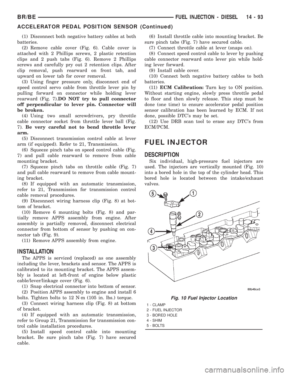
Six individual, high-pressure fuel injectors are
used. The injectors are vertically mounted (Fig. 10)
into a bored hole in the top of the cylinder head. This
bored hole is located between the intake/exhaust
valves.
Fig. 10 Fuel Injector Location
1 - CLAMP
2 - FUEL INJECTOR
3 - BORED HOLE
4 - SHIM
5 - BOLTS
BR/BEFUEL INJECTION - DIESEL 14 - 93
ACCELERATOR PEDAL POSITION SENSOR (Continued)