DODGE RAM 2001 Service Repair Manual
Manufacturer: DODGE, Model Year: 2001, Model line: RAM, Model: DODGE RAM 2001Pages: 2889, PDF Size: 68.07 MB
Page 2711 of 2889
(7) With seat back in a normal vertical position,
roll cover upwards and remove.
INSTALLATION
(1) With seat back in a normal vertical position,
roll cover downwards over seat back.
(2) Install hog rings, if equipped.
(3) Engage J-Straps at base of seat back.
(4) Align lumbar handle with lumbar cam and tap
on with rubber mallet until seated.
(5) Install latch release bezel.
(6) Install latch release knob.
(7) Install seat back. (Refer to 23 - BODY/SEATS/
SEAT BACK - SPLIT BENCH - INSTALLATION)
SEAT BACK RECLINER
REMOVAL
(1) Remove seat back. (Refer to 23 - BODY/SEATS/
SEAT BACK - SPLIT BENCH - REMOVAL)
(2) Disengage J-straps at base of seat back and
roll seat back cover upward to access rubber bellows
push-in fasteners.
NOTE: Notice the routing of the recliner cable for
installation.
(3) Remove the push-in fasteners attaching upper
rubber bellows to the seat back frame.
(4) Remove rubber bellows.
(5) Remove seat dump handle, 2±door ªBEº vehi-
cles only.
WARNING: Do not pull on upper recliner handle or
recliner cable end. The recliner lead screw is spring
loaded and will eject if either the handle or cable is
pulled before the lead screw is removed.
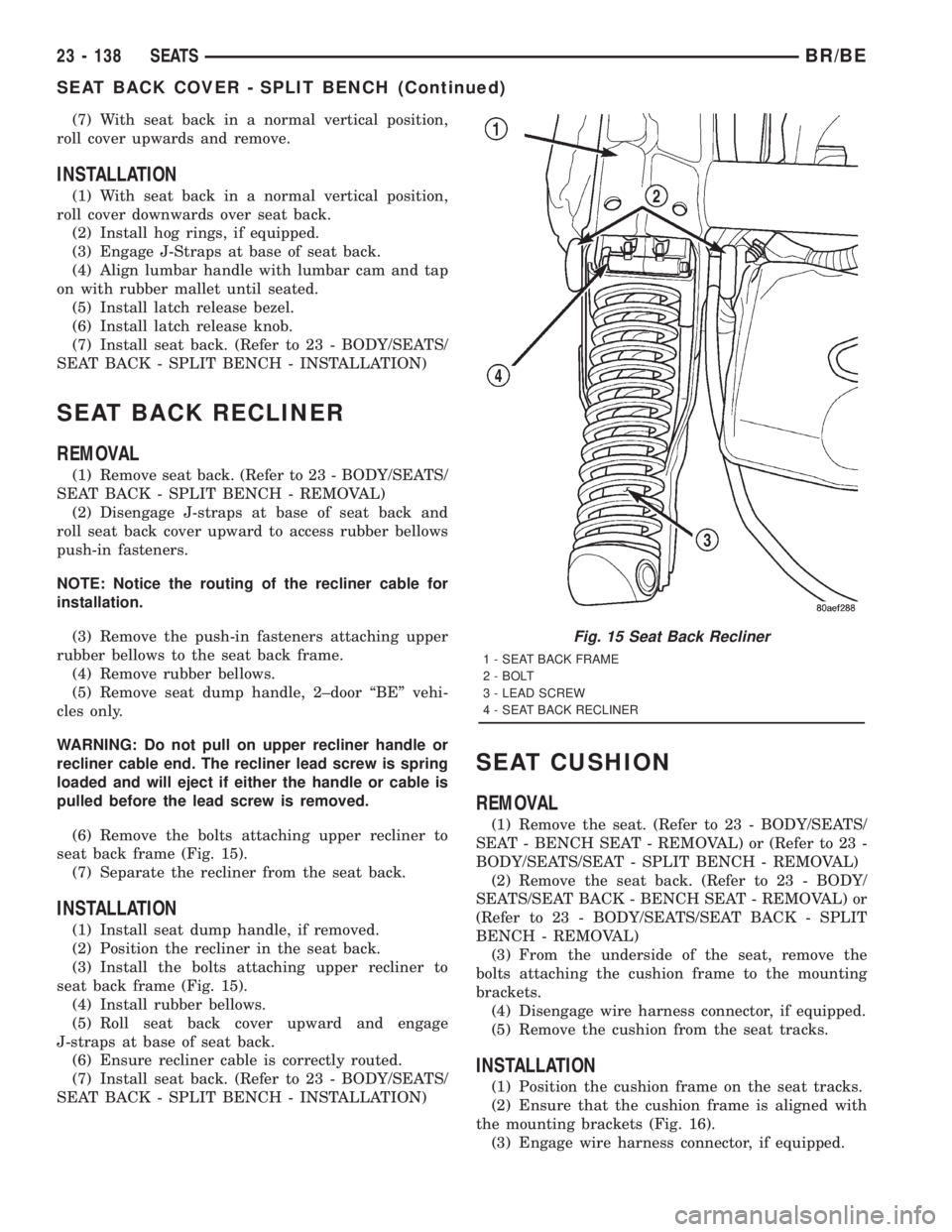
(6) Remove the bolts attaching upper recliner to
seat back frame (Fig. 15).
(7) Separate the recliner from the seat back.
INSTALLATION
(1) Install seat dump handle, if removed.
(2) Position the recliner in the seat back.
(3) Install the bolts attaching upper recliner to
seat back frame (Fig. 15).
(4) Install rubber bellows.
(5) Roll seat back cover upward and engage
J-straps at base of seat back.
(6) Ensure recliner cable is correctly routed.
(7) Install seat back. (Refer to 23 - BODY/SEATS/
SEAT BACK - SPLIT BENCH - INSTALLATION)
SEAT CUSHION
REMOVAL
(1) Remove the seat. (Refer to 23 - BODY/SEATS/
SEAT - BENCH SEAT - REMOVAL) or (Refer to 23 -
BODY/SEATS/SEAT - SPLIT BENCH - REMOVAL)
(2) Remove the seat back. (Refer to 23 - BODY/
SEATS/SEAT BACK - BENCH SEAT - REMOVAL) or
(Refer to 23 - BODY/SEATS/SEAT BACK - SPLIT
BENCH - REMOVAL)
(3) From the underside of the seat, remove the
bolts attaching the cushion frame to the mounting
brackets.
(4) Disengage wire harness connector, if equipped.
(5) Remove the cushion from the seat tracks.
INSTALLATION
(1) Position the cushion frame on the seat tracks.
(2) Ensure that the cushion frame is aligned with
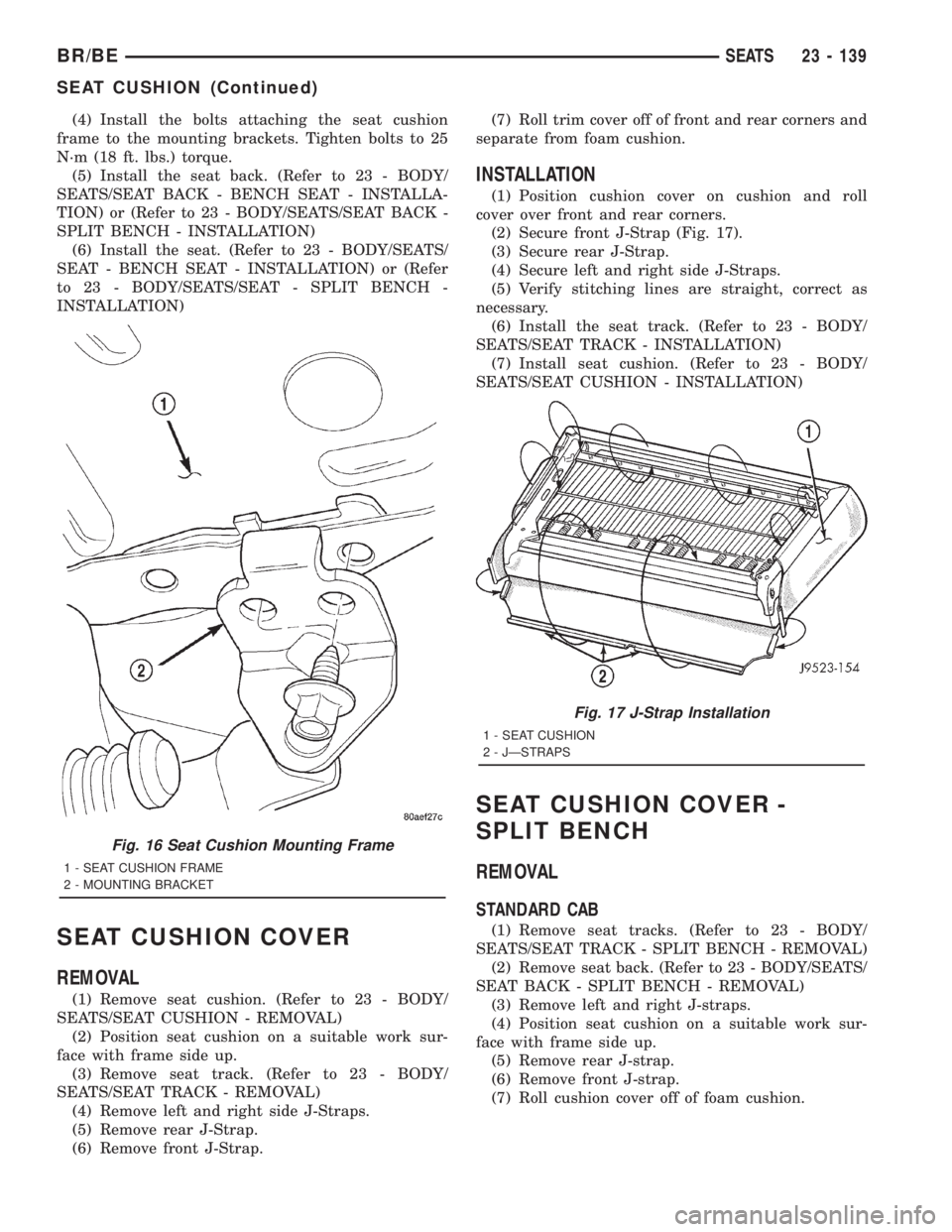
the mounting brackets (Fig. 16).
(3) Engage wire harness connector, if equipped.
Fig. 15 Seat Back Recliner
1 - SEAT BACK FRAME
2 - BOLT
3 - LEAD SCREW
4 - SEAT BACK RECLINER
23 - 138 SEATSBR/BE
SEAT BACK COVER - SPLIT BENCH (Continued)
Page 2712 of 2889
(4) Install the bolts attaching the seat cushion
frame to the mounting brackets. Tighten bolts to 25
N´m (18 ft. lbs.) torque.
(5) Install the seat back. (Refer to 23 - BODY/
SEATS/SEAT BACK - BENCH SEAT - INSTALLA-
TION) or (Refer to 23 - BODY/SEATS/SEAT BACK -
SPLIT BENCH - INSTALLATION)
(6) Install the seat. (Refer to 23 - BODY/SEATS/
SEAT - BENCH SEAT - INSTALLATION) or (Refer
to 23 - BODY/SEATS/SEAT - SPLIT BENCH -
INSTALLATION)
SEAT CUSHION COVER
REMOVAL
(1) Remove seat cushion. (Refer to 23 - BODY/
SEATS/SEAT CUSHION - REMOVAL)
(2) Position seat cushion on a suitable work sur-
face with frame side up.
(3) Remove seat track. (Refer to 23 - BODY/
SEATS/SEAT TRACK - REMOVAL)
(4) Remove left and right side J-Straps.
(5) Remove rear J-Strap.
(6) Remove front J-Strap.(7) Roll trim cover off of front and rear corners and
separate from foam cushion.
INSTALLATION
(1) Position cushion cover on cushion and roll
cover over front and rear corners.
(2) Secure front J-Strap (Fig. 17).
(3) Secure rear J-Strap.
(4) Secure left and right side J-Straps.
(5) Verify stitching lines are straight, correct as
necessary.
(6) Install the seat track. (Refer to 23 - BODY/
SEATS/SEAT TRACK - INSTALLATION)
(7) Install seat cushion. (Refer to 23 - BODY/
SEATS/SEAT CUSHION - INSTALLATION)
SEAT CUSHION COVER -
SPLIT BENCH
REMOVAL
STANDARD CAB
(1) Remove seat tracks. (Refer to 23 - BODY/
SEATS/SEAT TRACK - SPLIT BENCH - REMOVAL)
(2) Remove seat back. (Refer to 23 - BODY/SEATS/
SEAT BACK - SPLIT BENCH - REMOVAL)
(3) Remove left and right J-straps.
(4) Position seat cushion on a suitable work sur-
face with frame side up.
(5) Remove rear J-strap.
(6) Remove front J-strap.
(7) Roll cushion cover off of foam cushion.
Fig. 16 Seat Cushion Mounting Frame
1 - SEAT CUSHION FRAME
2 - MOUNTING BRACKET
Fig. 17 J-Strap Installation
1 - SEAT CUSHION
2 - JÐSTRAPS
BR/BESEATS 23 - 139
SEAT CUSHION (Continued)
Page 2713 of 2889
QUAD CAB
(1) Remove seat cushion. (Refer to 23 - BODY/
SEATS/SEAT CUSHION - REMOVAL)
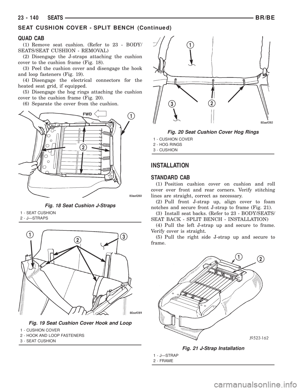
(2) Disengage the J-straps attaching the cushion
cover to the cushion frame (Fig. 18).
(3) Peel the cushion cover and disengage the hook
and loop fasteners (Fig. 19).
(4) Disengage the electrical connectors for the
heated seat grid, if equipped.
(5) Disengage the hog rings attaching the cushion
cover to the cushion frame (Fig. 20).
(6) Separate the cover from the cushion.
INSTALLATION
STANDARD CAB
(1) Position cushion cover on cushion and roll
cover over front and rear corners. Verify stitching
lines are straight, correct as necessary.
(2) Pull front J-strap up, align cover to foam
notches and secure front J-strap to frame (Fig. 21).
(3) Install seat backs. (Refer to 23 - BODY/SEATS/
SEAT BACK - SPLIT BENCH - INSTALLATION)
(4) Pull the left J-strap up and secure to frame.
Verify cover is straight.
(5) Pull the right side J-strap up and secure to
frame.
Fig. 21 J-Strap Installation
1 - JÐSTRAP
2 - FRAME
Fig. 18 Seat Cushion J-Straps
1 - SEAT CUSHION
2 - JÐSTRAPS
Fig. 19 Seat Cushion Cover Hook and Loop
1 - CUSHION COVER
2 - HOOK AND LOOP FASTENERS
3 - SEAT CUSHION
Fig. 20 Seat Cushion Cover Hog Rings
1 - CUSHION COVER
2 - HOG RINGS
3 - CUSHION
23 - 140 SEATSBR/BE
SEAT CUSHION COVER - SPLIT BENCH (Continued)
Page 2714 of 2889
(6) Install seat tracks. (Refer to 23 - BODY/
SEATS/SEAT TRACK - SPLIT BENCH - INSTALLA-
TION)
QUAD CAB
(1) Position the cover on the cushion.
(2) Engage the hog rings attaching the cushion
cover to the cushion frame.
(3) Engage the hook and loop fasteners.
(4) Engage the electrical connectors for the heated
seat grid, if equipped.
(5) Engage the J-straps attaching the cushion
cover to the cushion frame.
(6) Install seat cushion. (Refer to 23 - BODY/
SEATS/SEAT CUSHION - INSTALLATION)
SEAT RISER
REMOVAL
(1) Disconnect seat harness connector.
(2) Remove the seat from the vehicle. (Refer to 23 -
BODY/SEATS/SEAT - BENCH SEAT - REMOVAL) or
(Refer to 23 - BODY/SEATS/SEAT - SPLIT BENCH -
REMOVAL)
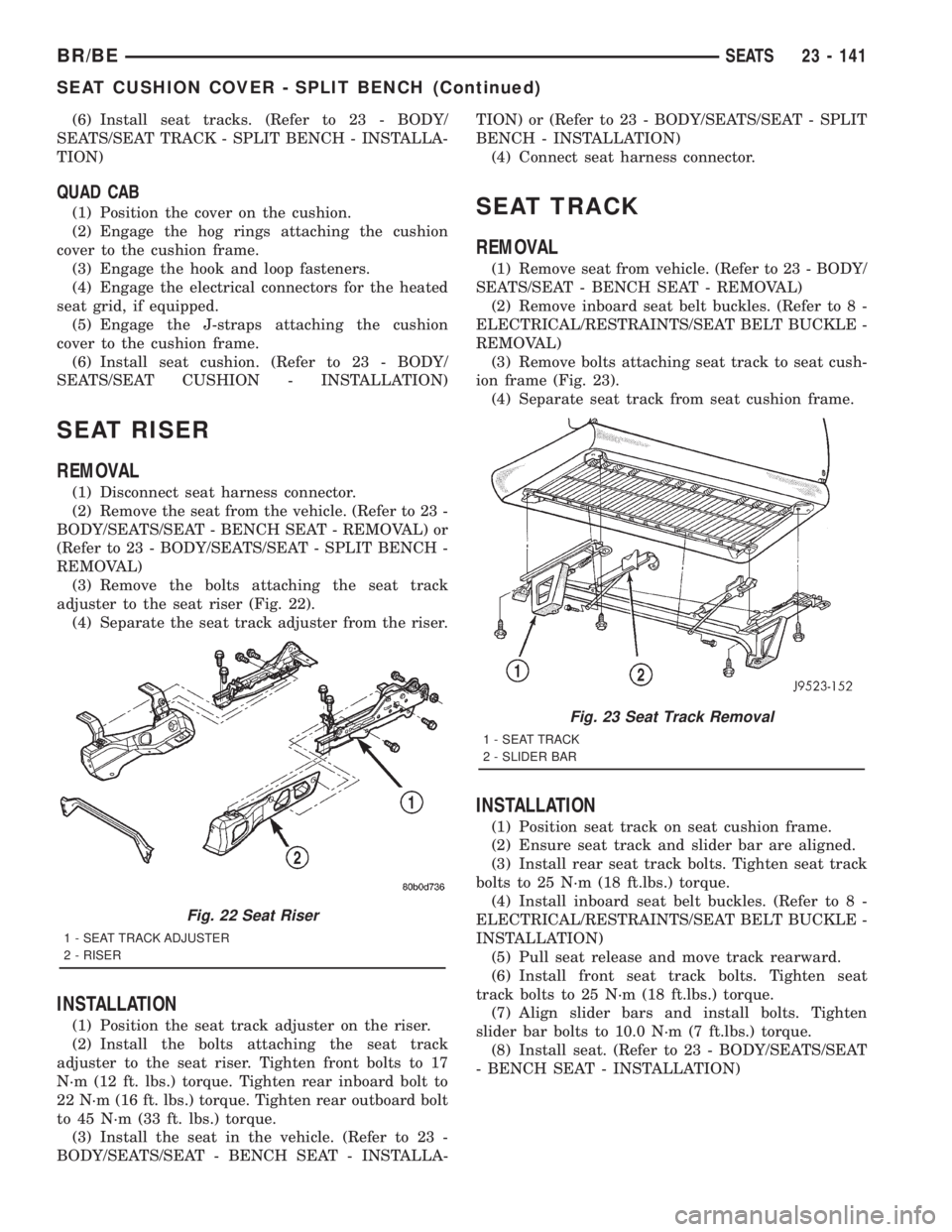
(3) Remove the bolts attaching the seat track
adjuster to the seat riser (Fig. 22).
(4) Separate the seat track adjuster from the riser.
INSTALLATION
(1) Position the seat track adjuster on the riser.
(2) Install the bolts attaching the seat track
adjuster to the seat riser. Tighten front bolts to 17
N´m (12 ft. lbs.) torque. Tighten rear inboard bolt to
22 N´m (16 ft. lbs.) torque. Tighten rear outboard bolt
to 45 N´m (33 ft. lbs.) torque.
(3) Install the seat in the vehicle. (Refer to 23 -
BODY/SEATS/SEAT - BENCH SEAT - INSTALLA-TION) or (Refer to 23 - BODY/SEATS/SEAT - SPLIT
BENCH - INSTALLATION)
(4) Connect seat harness connector.
SEAT TRACK
REMOVAL
(1) Remove seat from vehicle. (Refer to 23 - BODY/
SEATS/SEAT - BENCH SEAT - REMOVAL)
(2) Remove inboard seat belt buckles. (Refer to 8 -
ELECTRICAL/RESTRAINTS/SEAT BELT BUCKLE -
REMOVAL)
(3) Remove bolts attaching seat track to seat cush-
ion frame (Fig. 23).
(4) Separate seat track from seat cushion frame.
INSTALLATION
(1) Position seat track on seat cushion frame.
(2) Ensure seat track and slider bar are aligned.
(3) Install rear seat track bolts. Tighten seat track
bolts to 25 N´m (18 ft.lbs.) torque.
(4) Install inboard seat belt buckles. (Refer to 8 -
ELECTRICAL/RESTRAINTS/SEAT BELT BUCKLE -
INSTALLATION)
(5) Pull seat release and move track rearward.
(6) Install front seat track bolts. Tighten seat
track bolts to 25 N´m (18 ft.lbs.) torque.
(7) Align slider bars and install bolts. Tighten
slider bar bolts to 10.0 N´m (7 ft.lbs.) torque.
(8) Install seat. (Refer to 23 - BODY/SEATS/SEAT
- BENCH SEAT - INSTALLATION)
Fig. 22 Seat Riser
1 - SEAT TRACK ADJUSTER
2 - RISER
Fig. 23 Seat Track Removal
1 - SEAT TRACK
2 - SLIDER BAR
BR/BESEATS 23 - 141
SEAT CUSHION COVER - SPLIT BENCH (Continued)
Page 2715 of 2889
SEAT TRACK - SPLIT BENCH
REMOVAL
(1) Remove seat from vehicle. (Refer to 23 -
BODY/SEATS/SEAT - SPLIT BENCH - REMOVAL)
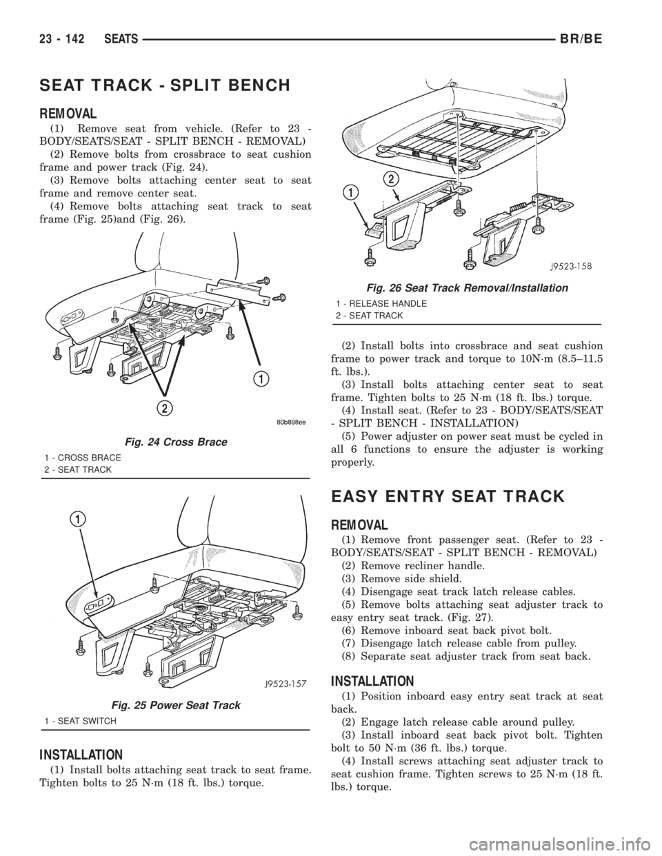
(2) Remove bolts from crossbrace to seat cushion
frame and power track (Fig. 24).
(3) Remove bolts attaching center seat to seat
frame and remove center seat.
(4) Remove bolts attaching seat track to seat
frame (Fig. 25)and (Fig. 26).
INSTALLATION
(1) Install bolts attaching seat track to seat frame.
Tighten bolts to 25 N´m (18 ft. lbs.) torque.(2) Install bolts into crossbrace and seat cushion
frame to power track and torque to 10N´m (8.5±11.5
ft. lbs.).
(3) Install bolts attaching center seat to seat
frame. Tighten bolts to 25 N´m (18 ft. lbs.) torque.
(4) Install seat. (Refer to 23 - BODY/SEATS/SEAT
- SPLIT BENCH - INSTALLATION)
(5) Power adjuster on power seat must be cycled in
all 6 functions to ensure the adjuster is working
properly.
EASY ENTRY SEAT TRACK
REMOVAL
(1) Remove front passenger seat. (Refer to 23 -
BODY/SEATS/SEAT - SPLIT BENCH - REMOVAL)
(2) Remove recliner handle.
(3) Remove side shield.
(4) Disengage seat track latch release cables.
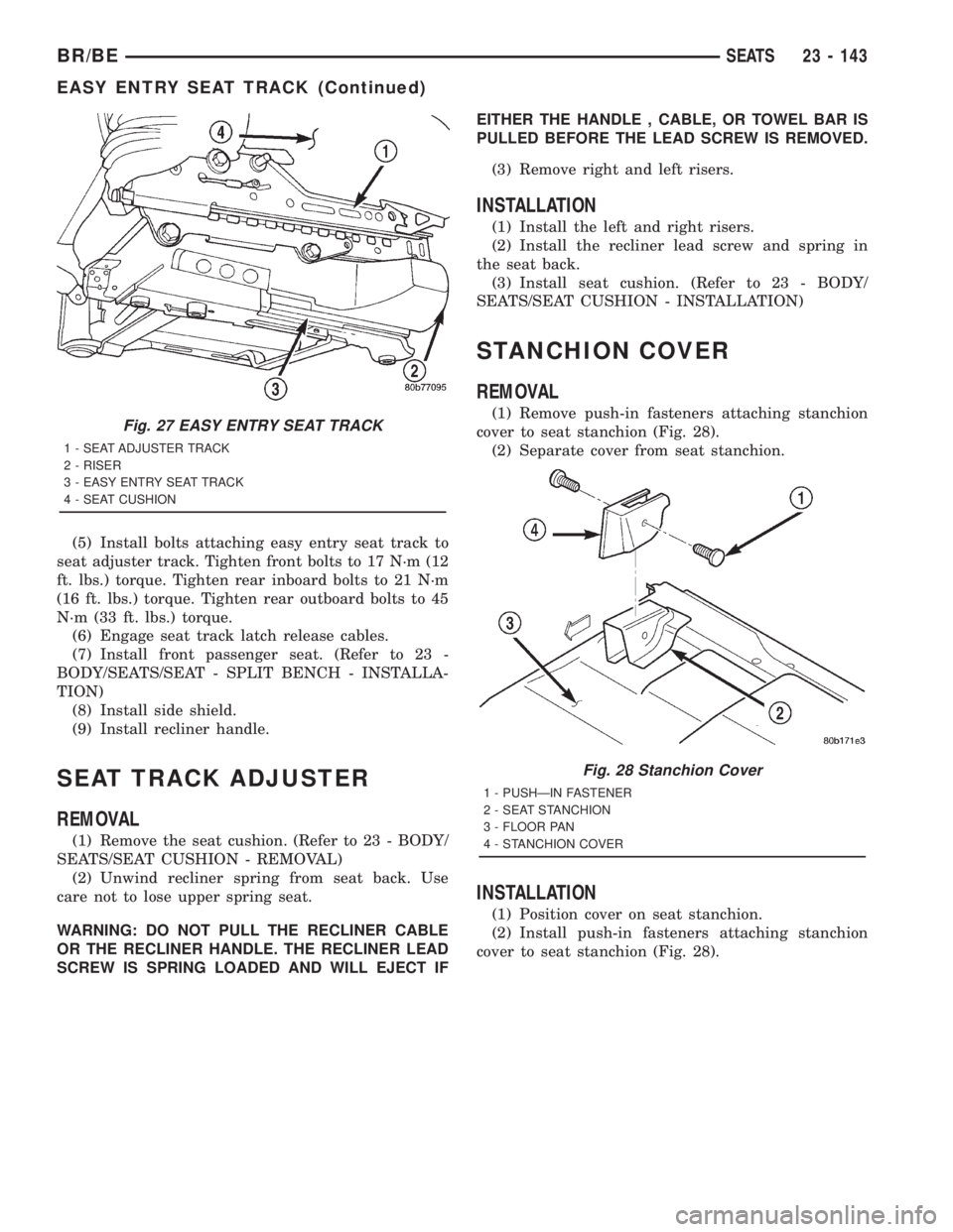
(5) Remove bolts attaching seat adjuster track to
easy entry seat track. (Fig. 27).
(6) Remove inboard seat back pivot bolt.
(7) Disengage latch release cable from pulley.
(8) Separate seat adjuster track from seat back.
INSTALLATION
(1) Position inboard easy entry seat track at seat
back.
(2) Engage latch release cable around pulley.
(3) Install inboard seat back pivot bolt. Tighten
bolt to 50 N´m (36 ft. lbs.) torque.
(4) Install screws attaching seat adjuster track to
seat cushion frame. Tighten screws to 25 N´m (18 ft.
lbs.) torque.
Fig. 24 Cross Brace
1 - CROSS BRACE
2 - SEAT TRACK
Fig. 25 Power Seat Track
1 - SEAT SWITCH
Fig. 26 Seat Track Removal/Installation
1 - RELEASE HANDLE
2 - SEAT TRACK
23 - 142 SEATSBR/BE
Page 2716 of 2889
(5) Install bolts attaching easy entry seat track to
seat adjuster track. Tighten front bolts to 17 N´m (12
ft. lbs.) torque. Tighten rear inboard bolts to 21 N´m
(16 ft. lbs.) torque. Tighten rear outboard bolts to 45
N´m (33 ft. lbs.) torque.
(6) Engage seat track latch release cables.
(7) Install front passenger seat. (Refer to 23 -
BODY/SEATS/SEAT - SPLIT BENCH - INSTALLA-
TION)
(8) Install side shield.
(9) Install recliner handle.
SEAT TRACK ADJUSTER
REMOVAL
(1) Remove the seat cushion. (Refer to 23 - BODY/
SEATS/SEAT CUSHION - REMOVAL)
(2) Unwind recliner spring from seat back. Use
care not to lose upper spring seat.
WARNING: DO NOT PULL THE RECLINER CABLE
OR THE RECLINER HANDLE. THE RECLINER LEAD
SCREW IS SPRING LOADED AND WILL EJECT IFEITHER THE HANDLE , CABLE, OR TOWEL BAR IS
PULLED BEFORE THE LEAD SCREW IS REMOVED.
(3) Remove right and left risers.
INSTALLATION
(1) Install the left and right risers.
(2) Install the recliner lead screw and spring in
the seat back.
(3) Install seat cushion. (Refer to 23 - BODY/
SEATS/SEAT CUSHION - INSTALLATION)
STANCHION COVER
REMOVAL
(1) Remove push-in fasteners attaching stanchion
cover to seat stanchion (Fig. 28).
(2) Separate cover from seat stanchion.
INSTALLATION
(1) Position cover on seat stanchion.
(2) Install push-in fasteners attaching stanchion
cover to seat stanchion (Fig. 28).
Fig. 27 EASY ENTRY SEAT TRACK
1 - SEAT ADJUSTER TRACK
2 - RISER
3 - EASY ENTRY SEAT TRACK
4 - SEAT CUSHION
Fig. 28 Stanchion Cover
1 - PUSHÐIN FASTENER
2 - SEAT STANCHION
3 - FLOOR PAN
4 - STANCHION COVER
BR/BESEATS 23 - 143
EASY ENTRY SEAT TRACK (Continued)
Page 2717 of 2889
REAR SEAT
REMOVAL
(1) Move front seat track to full forward position.
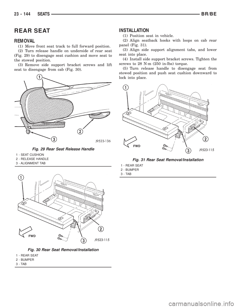
(2) Turn release handle on underside of rear seat
(Fig. 29) to disengage seat cushion and move seat to
the stowed position.
(3) Remove side support bracket screws and lift
seat to disengage from cab (Fig. 30).
INSTALLATION
(1) Position seat in vehicle.
(2) Align seatback hooks with loops on cab rear
panel (Fig. 31).
(3) Align side support alignment tabs, and lower
seat into place.
(4) Install side support bracket screws. Tighten the
screws to 28 N´m (250 in-lbs) torque.
(5) Turn release handle to disengage seat from
stowed position and push seat cushion downward to
lock into place.
Fig. 29 Rear Seat Release Handle
1 - SEAT CUSHION
2 - RELEASE HANDLE
3 - ALIGNMENT TAB
Fig. 30 Rear Seat Removal/Installation
1 - REAR SEAT
2 - BUMPER
3-TAB
Fig. 31 Rear Seat Removal/Installation
1 - REAR SEAT
2 - BUMPER
3-TAB
23 - 144 SEATSBR/BE
Page 2718 of 2889
STATIONARY GLASS
TABLE OF CONTENTS
page page
STATIONARY GLASS
DESCRIPTION..........................145
OPERATION............................145
BACKLITE
REMOVAL.............................145
INSTALLATION..........................145
BACKLITE LATCH AND KEEPER
REMOVAL.............................146
INSTALLATION..........................146
BACKLITE VENT GLASS
REMOVAL.............................147INSTALLATION..........................147
WINDSHIELD
DESCRIPTION..........................148
REMOVAL.............................148
INSTALLATION..........................148
QUARTER WINDOW
REMOVAL.............................151
INSTALLATION..........................151
STATIONARY GLASS
DESCRIPTION
Windshields are made of two pieces of glass with a
plastic inner layer. Windshields and selected station-
ary glass are structural members of the vehicle. The
windshield glass is bonded to the windshield frame
with urethane adhesive.
OPERATION
Windshields and other stationary glass protect the
occupants from the effects of the elements. Wind-
shields are also used to retain some airbags in posi-
tion during deployment. Urethane bonded glass is
difficult to salvage during removal. The urethane
bonding is difficult to cut or clean from any surface.
Before removing the glass, check the availability of
replacement components.
BACKLITE
REMOVAL
It is difficult to salvage the backlite during the
removal operation. The backlite is part of the struc-
tural support for the roof. The urethane bonding
used to secure the glass to the fence is difficult to cut
or clean from any surface. Since the molding is set in
urethane, it is unlikely it would be salvaged. Before
removing the backlite, check the availability from the
parts supplier.
The backlite is attached to the window frame with
urethane adhesive. The urethane adhesive is applied
cold and seals the surface area between the window
opening and the glass. The primer adheres the ure-
thane adhesive to the backlite.(1) Roll down door glass.
(2) Remove headliner. (Refer to 23 - BODY/INTE-
RIOR/HEADLINER - REMOVAL).
(3) Remove rear closer panel trim. (Refer to 23 -
BODY/INTERIOR/REAR CLOSURE PANEL TRIM -
REMOVAL).
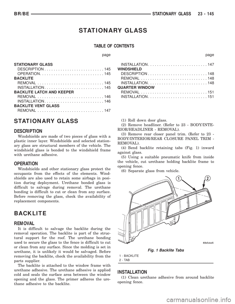
(4) Bend backlite retaining tabs (Fig. 1) inward
against glass.
(5) Using a suitable pneumatic knife from inside
the vehicle, cut urethane holding backlite frame to
opening fence.
(6) Separate glass from vehicle.
INSTALLATION
(1) Clean urethane adhesive from around backlite
opening fence.
Fig. 1 Backlite Tabs
1 - BACKLITE
2-TAB
BR/BESTATIONARY GLASS 23 - 145
Page 2719 of 2889
(2) If necessary, apply black-out primer to outer
edge of replacement backlite frame.
(3) If black-out primer was pre-applied on backlite,
clean bonding surface with Isopropyl alcohol and
clean lint free cloth. Allow 3 minutes for drying time.
(4) Apply black-out primer to backlite opening
fence.
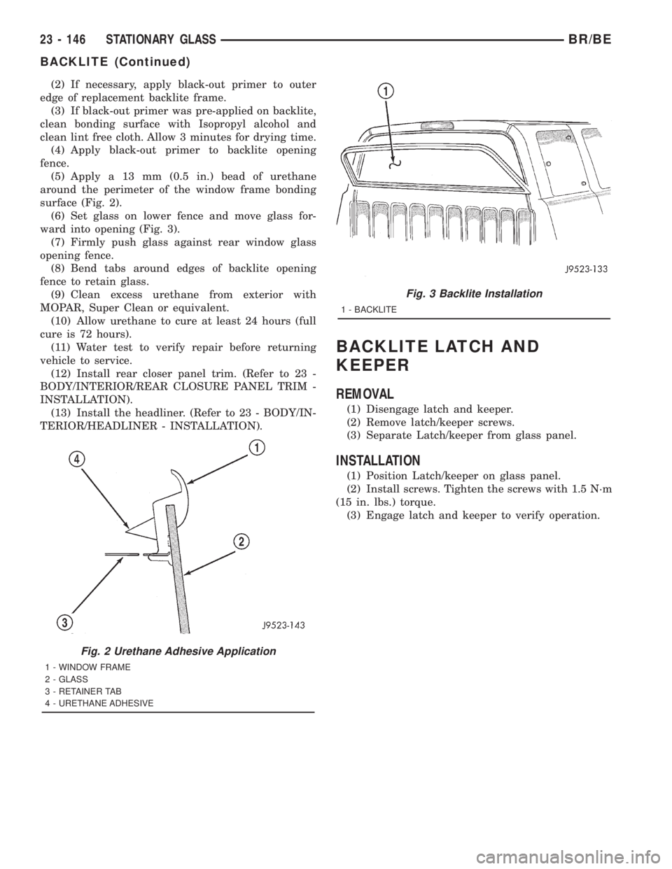
(5) Apply a 13 mm (0.5 in.) bead of urethane
around the perimeter of the window frame bonding
surface (Fig. 2).
(6) Set glass on lower fence and move glass for-
ward into opening (Fig. 3).
(7) Firmly push glass against rear window glass
opening fence.
(8) Bend tabs around edges of backlite opening
fence to retain glass.
(9) Clean excess urethane from exterior with
MOPAR, Super Clean or equivalent.
(10) Allow urethane to cure at least 24 hours (full
cure is 72 hours).
(11) Water test to verify repair before returning
vehicle to service.
(12) Install rear closer panel trim. (Refer to 23 -
BODY/INTERIOR/REAR CLOSURE PANEL TRIM -
INSTALLATION).
(13) Install the headliner. (Refer to 23 - BODY/IN-
TERIOR/HEADLINER - INSTALLATION).
BACKLITE LATCH AND
KEEPER
REMOVAL
(1) Disengage latch and keeper.
(2) Remove latch/keeper screws.
(3) Separate Latch/keeper from glass panel.
INSTALLATION
(1) Position Latch/keeper on glass panel.
(2) Install screws. Tighten the screws with 1.5 N´m
(15 in. lbs.) torque.
(3) Engage latch and keeper to verify operation.
Fig. 2 Urethane Adhesive Application
1 - WINDOW FRAME
2 - GLASS
3 - RETAINER TAB
4 - URETHANE ADHESIVE
Fig. 3 Backlite Installation
1 - BACKLITE
23 - 146 STATIONARY GLASSBR/BE
BACKLITE (Continued)
Page 2720 of 2889
BACKLITE VENT GLASS
REMOVAL
(1) Close and latch sliding vent glass.
(2) Remove rear closure panel trim, if necessary.
(Refer to 23 - BODY/INTERIOR/REAR CLOSURE
PANEL TRIM - REMOVAL).
(3) Grasp end of lower run channel.
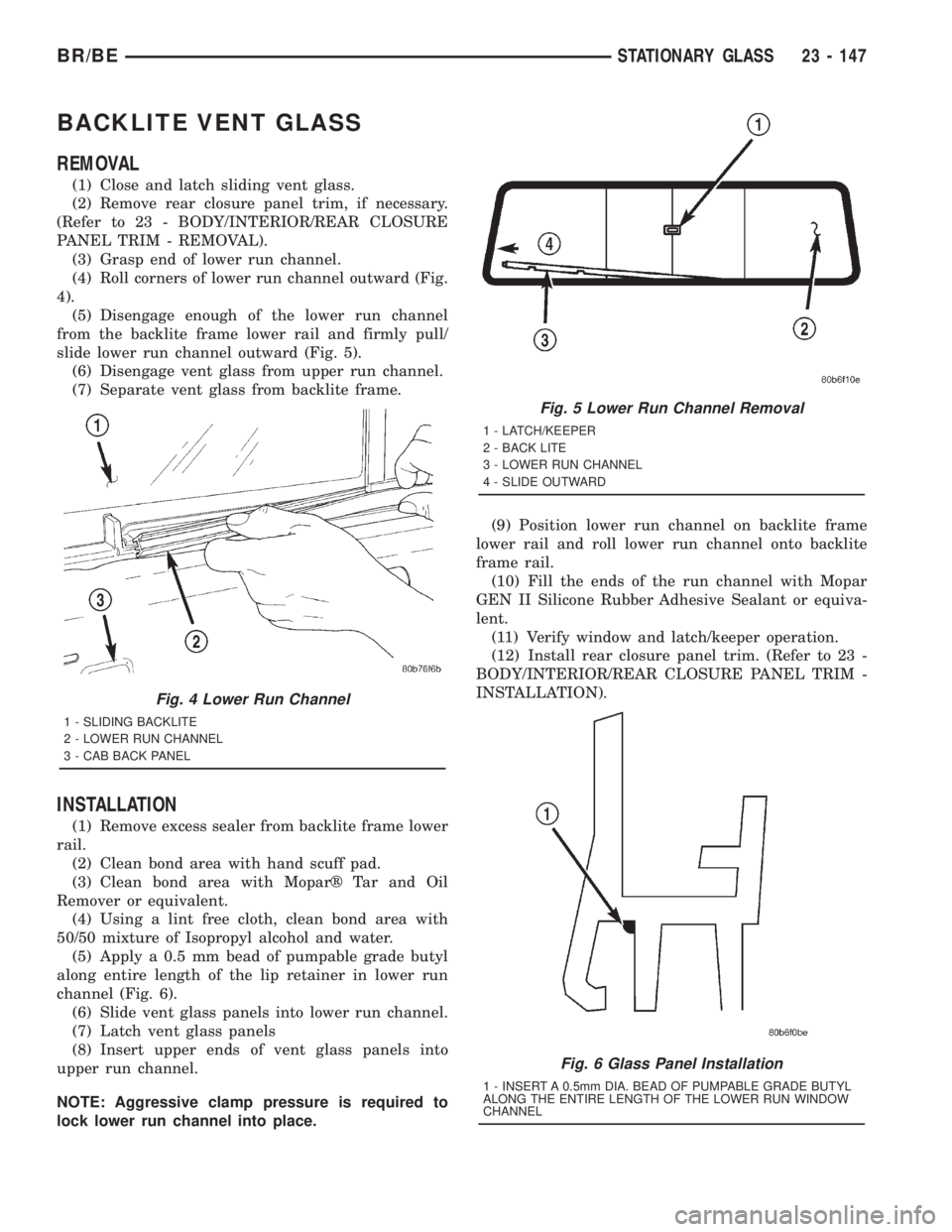
(4) Roll corners of lower run channel outward (Fig.
4).
(5) Disengage enough of the lower run channel
from the backlite frame lower rail and firmly pull/
slide lower run channel outward (Fig. 5).
(6) Disengage vent glass from upper run channel.
(7) Separate vent glass from backlite frame.
INSTALLATION
(1) Remove excess sealer from backlite frame lower
rail.
(2) Clean bond area with hand scuff pad.
(3) Clean bond area with Moparž Tar and Oil
Remover or equivalent.
(4) Using a lint free cloth, clean bond area with
50/50 mixture of Isopropyl alcohol and water.
(5) Apply a 0.5 mm bead of pumpable grade butyl
along entire length of the lip retainer in lower run
channel (Fig. 6).
(6) Slide vent glass panels into lower run channel.
(7) Latch vent glass panels
(8) Insert upper ends of vent glass panels into
upper run channel.
NOTE: Aggressive clamp pressure is required to
lock lower run channel into place.(9) Position lower run channel on backlite frame
lower rail and roll lower run channel onto backlite
frame rail.
(10) Fill the ends of the run channel with Mopar
GEN II Silicone Rubber Adhesive Sealant or equiva-
lent.
(11) Verify window and latch/keeper operation.
(12) Install rear closure panel trim. (Refer to 23 -
BODY/INTERIOR/REAR CLOSURE PANEL TRIM -
INSTALLATION).
Fig. 4 Lower Run Channel
1 - SLIDING BACKLITE
2 - LOWER RUN CHANNEL
3 - CAB BACK PANEL
Fig. 5 Lower Run Channel Removal
1 - LATCH/KEEPER
2 - BACK LITE
3 - LOWER RUN CHANNEL
4 - SLIDE OUTWARD
Fig. 6 Glass Panel Installation
1 - INSERT A 0.5mm DIA. BEAD OF PUMPABLE GRADE BUTYL
ALONG THE ENTIRE LENGTH OF THE LOWER RUN WINDOW
CHANNEL
BR/BESTATIONARY GLASS 23 - 147