DODGE RAM 2001 Service Repair Manual
Manufacturer: DODGE, Model Year: 2001, Model line: RAM, Model: DODGE RAM 2001Pages: 2889, PDF Size: 68.07 MB
Page 2821 of 2889
REMOVAL
The LDP and LDP filter are attached to a bracket
mounted to the right-inner fender (Fig. 2). The LDP
and LDP filter are replaced (serviced) as one unit.
(1) Carefully remove hose at LDP filter.
(2) Remove LDP filter mounting bolt and remove
from vehicle.
(3) Carefully remove vapor/vacuum lines at LDP.
(4) Disconnect electrical connector at LDP (Fig. 2).
(5) Remove LDP mounting screws and remove
LDP from vehicle.
INSTALLATION
The LDP and LDP filter are attached to a bracket
mounted to the right-inner fender (Fig. 2). The LDP
and LDP filter are replaced (serviced) as one unit.(1) Install LDP to mounting bracket. Tighten
screws to 1 N´m (11 in. lbs.) torque.
(2) Install LDP filter to mounting bracket. Tighten
bolt to 7 N´m (65 in. lbs.) torque.
(3) Carefully install vapor/vacuum lines to LDP,
and install hose to LDP filter.The vapor/vacuum
lines and hoses must be firmly connected.
Check the vapor/vacuum lines at the LDP, LDP
filter and EVAP canister purge solenoid for
damage or leaks. If a leak is present, a Diagnos-
tic Trouble Code (DTC) may be set.
(4) Connect electrical connector to LDP.
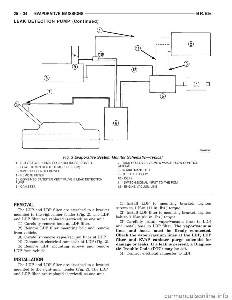
Fig. 3 Evaporative System Monitor SchematicÐTypical
1 - DUTY CYCLE PURGE SOLENOID (DCPS) DRIVER
2 - POWERTRAIN CONTROL MODULE (PCM)
3 - 3-PORT SOLENOID DRIVER
4 - REMOTE FILTER
5 - COMBINED CANISTER VENT VALVE & LEAK DETECTION
PUMP
6 - CANISTER7 - TANK ROLLOVER VALVE & VAPOR FLOW CONTROL
ORIFICE
8 - INTAKE MANIFOLD
9 - THROTTLE BODY
10 - DCPS
11 - SWITCH SIGNAL INPUT TO THE PCM
12 - ENGINE VACUUM LINE
25 - 34 EVAPORATIVE EMISSIONSBR/BE
LEAK DETECTION PUMP (Continued)
Page 2822 of 2889
PCV FILTER
DESCRIPTION
The crankcase breather/filter is no longer used
with the 3.9L, 5.2L or 5.9L engine.
PCV VALVE
DESCRIPTION - V-6/V-8 ENGINES
All 3.9L V-6 and 5.2L/5.9L V-8 gas powered engines
are equipped with a closed crankcase ventilation sys-
tem and a positive crankcase ventilation (PCV) valve.
The 8.0L V-10 engine is not equipped with a PCV
valve. Refer to Crankcase Ventilation SystemÐ8.0L
V-10 Engine for information.
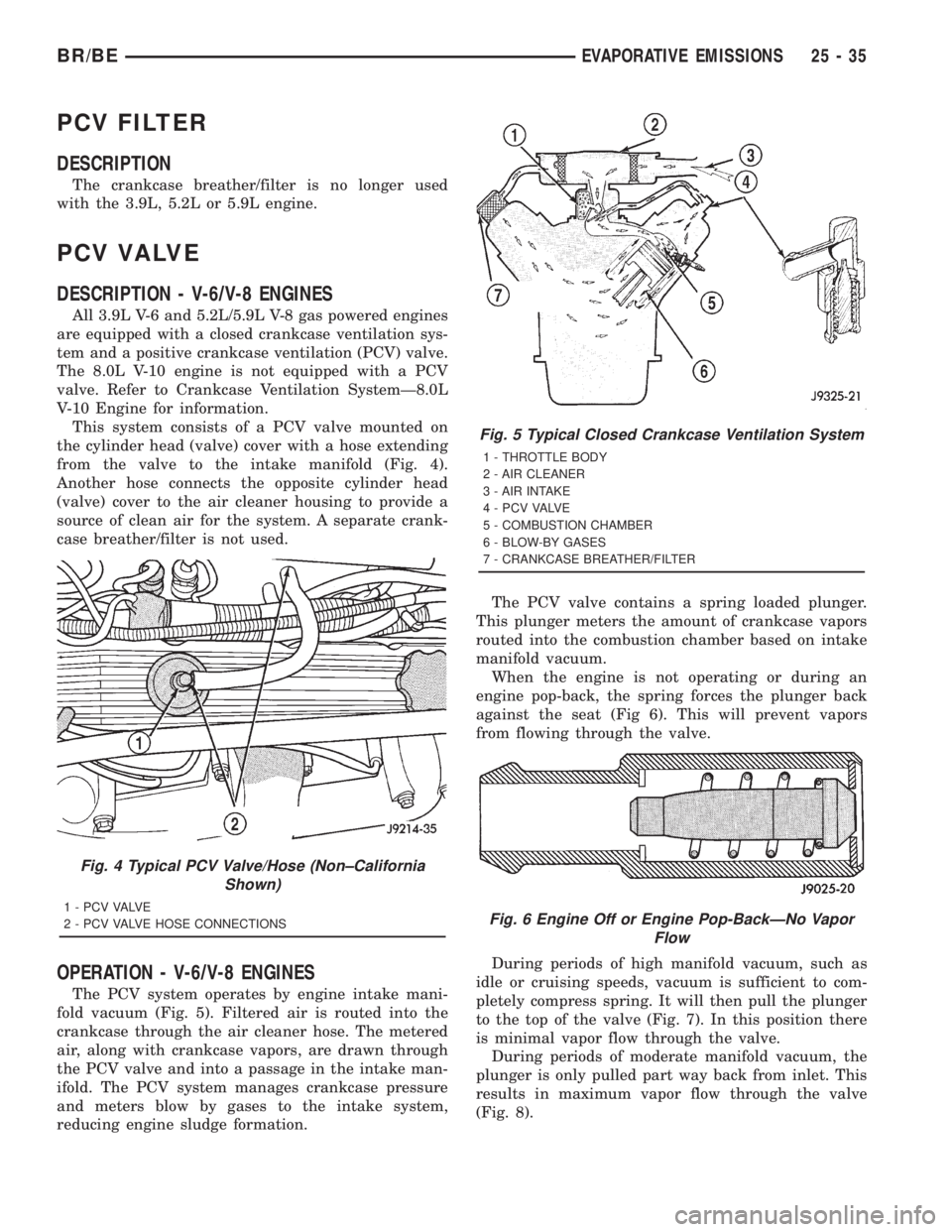
This system consists of a PCV valve mounted on
the cylinder head (valve) cover with a hose extending
from the valve to the intake manifold (Fig. 4).
Another hose connects the opposite cylinder head
(valve) cover to the air cleaner housing to provide a
source of clean air for the system. A separate crank-
case breather/filter is not used.
OPERATION - V-6/V-8 ENGINES
The PCV system operates by engine intake mani-
fold vacuum (Fig. 5). Filtered air is routed into the
crankcase through the air cleaner hose. The metered
air, along with crankcase vapors, are drawn through
the PCV valve and into a passage in the intake man-
ifold. The PCV system manages crankcase pressure
and meters blow by gases to the intake system,
reducing engine sludge formation.The PCV valve contains a spring loaded plunger.
This plunger meters the amount of crankcase vapors
routed into the combustion chamber based on intake
manifold vacuum.
When the engine is not operating or during an
engine pop-back, the spring forces the plunger back
against the seat (Fig 6). This will prevent vapors
from flowing through the valve.
During periods of high manifold vacuum, such as
idle or cruising speeds, vacuum is sufficient to com-
pletely compress spring. It will then pull the plunger
to the top of the valve (Fig. 7). In this position there
is minimal vapor flow through the valve.
During periods of moderate manifold vacuum, the
plunger is only pulled part way back from inlet. This
results in maximum vapor flow through the valve
(Fig. 8).
Fig. 4 Typical PCV Valve/Hose (Non±California
Shown)
1 - P C V VA LV E
2 - PCV VALVE HOSE CONNECTIONS
Fig. 5 Typical Closed Crankcase Ventilation System
1 - THROTTLE BODY
2 - AIR CLEANER
3 - AIR INTAKE
4 - P C V VA LV E
5 - COMBUSTION CHAMBER
6 - BLOW-BY GASES
7 - CRANKCASE BREATHER/FILTER
Fig. 6 Engine Off or Engine Pop-BackÐNo Vapor
Flow
BR/BEEVAPORATIVE EMISSIONS 25 - 35
Page 2823 of 2889
DIAGNOSIS AND TESTING - PCV VALVE -
V±6/V±8 ENGINES
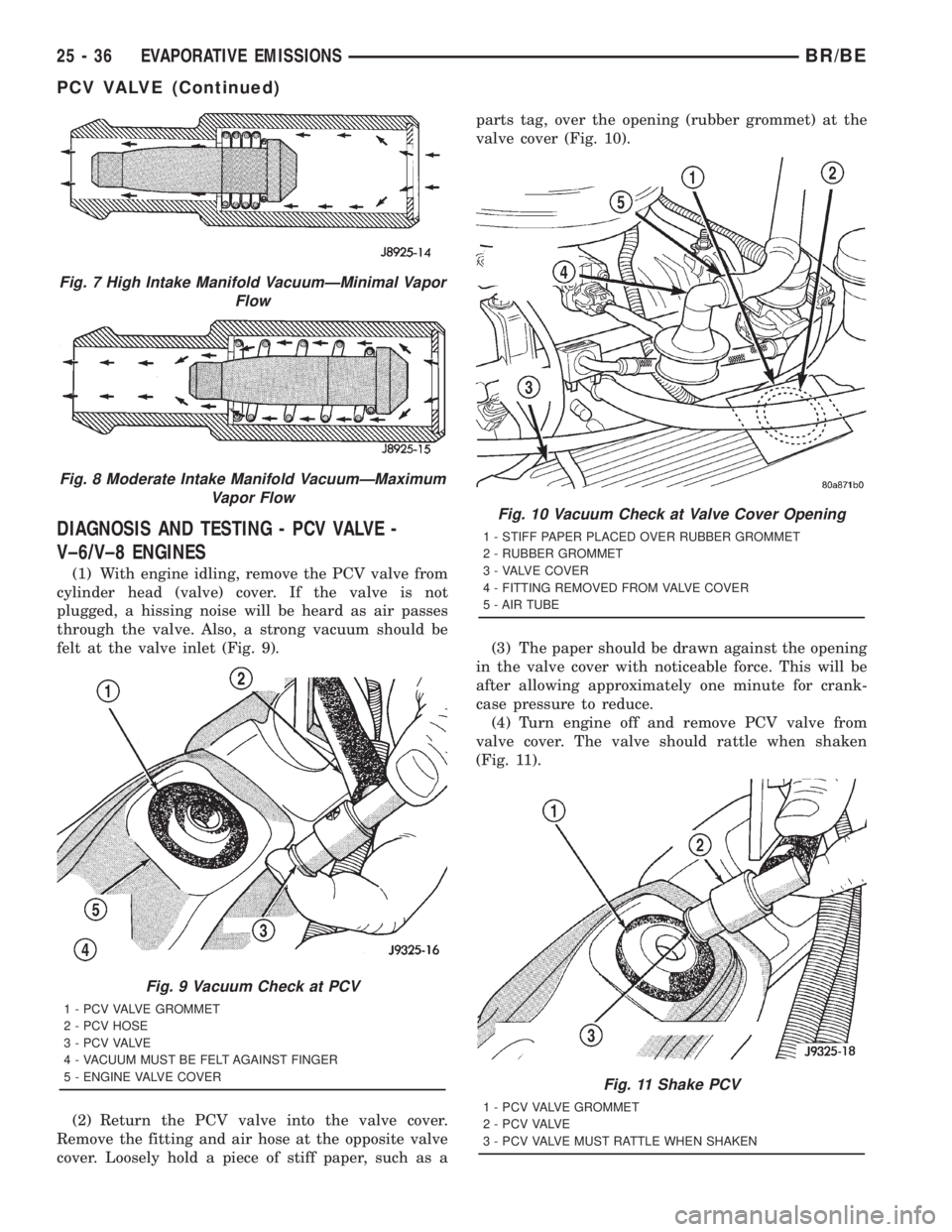
(1) With engine idling, remove the PCV valve from
cylinder head (valve) cover. If the valve is not
plugged, a hissing noise will be heard as air passes
through the valve. Also, a strong vacuum should be
felt at the valve inlet (Fig. 9).
(2) Return the PCV valve into the valve cover.
Remove the fitting and air hose at the opposite valve
cover. Loosely hold a piece of stiff paper, such as aparts tag, over the opening (rubber grommet) at the
valve cover (Fig. 10).
(3) The paper should be drawn against the opening
in the valve cover with noticeable force. This will be
after allowing approximately one minute for crank-
case pressure to reduce.
(4) Turn engine off and remove PCV valve from
valve cover. The valve should rattle when shaken
(Fig. 11).
Fig. 7 High Intake Manifold VacuumÐMinimal Vapor
Flow
Fig. 8 Moderate Intake Manifold VacuumÐMaximum
Vapor Flow
Fig. 9 Vacuum Check at PCV
1 - PCV VALVE GROMMET
2 - PCV HOSE
3 - P C V VA LV E
4 - VACUUM MUST BE FELT AGAINST FINGER
5 - ENGINE VALVE COVER
Fig. 10 Vacuum Check at Valve Cover Opening
1 - STIFF PAPER PLACED OVER RUBBER GROMMET
2 - RUBBER GROMMET
3 - VALVE COVER
4 - FITTING REMOVED FROM VALVE COVER
5 - AIR TUBE
Fig. 11 Shake PCV
1 - PCV VALVE GROMMET
2 - P C V VA LV E
3 - PCV VALVE MUST RATTLE WHEN SHAKEN
25 - 36 EVAPORATIVE EMISSIONSBR/BE
PCV VALVE (Continued)
Page 2824 of 2889
(5) Replace the PCV valve and retest the system if
it does not operate as described in the preceding
tests.Do not attempt to clean the old PCV valve.
(6) If the paper is not held against the opening in
valve cover after new valve is installed, the PCV
valve hose may be restricted and must be replaced.
The passage in the intake manifold must also be
checked and cleaned.
(7) To clean the intake manifold fitting, turn a 1/4
inch drill (by hand) through the fitting to dislodge
any solid particles. Blow out the fitting with shop air.
If necessary, use a smaller drill to avoid removing
any metal from the fitting.
VACUUM LINES
DIAGNOSIS AND TESTING - VACUUM
SCHEMATICS
A vacuum schematic for emission related items can
be found on the VECI label. Refer to Vehicle Emis-
sion Control Information (VECI) Label in this group
for label location.
VAPOR CANISTER
DESCRIPTION
Two, maintenance free, EVAP canisters are used
with all 3.9L/5.2L/5.9L/8.0L gasoline powered
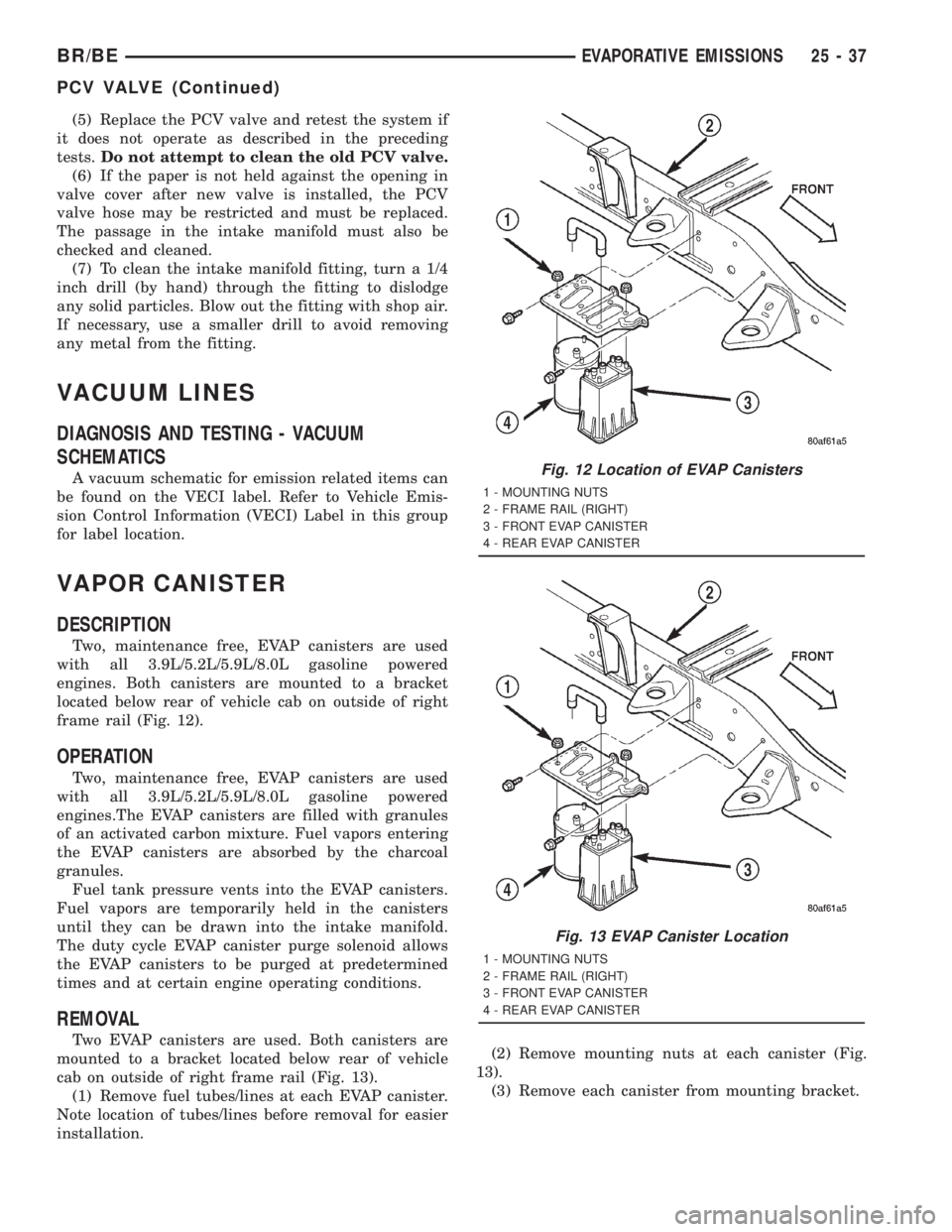
engines. Both canisters are mounted to a bracket
located below rear of vehicle cab on outside of right
frame rail (Fig. 12).
OPERATION
Two, maintenance free, EVAP canisters are used
with all 3.9L/5.2L/5.9L/8.0L gasoline powered
engines.The EVAP canisters are filled with granules
of an activated carbon mixture. Fuel vapors entering
the EVAP canisters are absorbed by the charcoal
granules.
Fuel tank pressure vents into the EVAP canisters.
Fuel vapors are temporarily held in the canisters
until they can be drawn into the intake manifold.
The duty cycle EVAP canister purge solenoid allows
the EVAP canisters to be purged at predetermined
times and at certain engine operating conditions.
REMOVAL
Two EVAP canisters are used. Both canisters are
mounted to a bracket located below rear of vehicle
cab on outside of right frame rail (Fig. 13).
(1) Remove fuel tubes/lines at each EVAP canister.
Note location of tubes/lines before removal for easier
installation.(2) Remove mounting nuts at each canister (Fig.
13).
(3) Remove each canister from mounting bracket.
Fig. 12 Location of EVAP Canisters
1 - MOUNTING NUTS
2 - FRAME RAIL (RIGHT)
3 - FRONT EVAP CANISTER
4 - REAR EVAP CANISTER
Fig. 13 EVAP Canister Location
1 - MOUNTING NUTS
2 - FRAME RAIL (RIGHT)
3 - FRONT EVAP CANISTER
4 - REAR EVAP CANISTER
BR/BEEVAPORATIVE EMISSIONS 25 - 37
PCV VALVE (Continued)
Page 2825 of 2889

INSTALLATION
Two EVAP canisters are used. Both canisters are
mounted to a bracket located below rear of vehicle
cab on outside of right frame rail (Fig. 13).(1) Place each canister to mounting bracket (Fig.
13).
(2) Install nuts and tighten to 9 N´m (80 in. lbs.)
torque.
(3) Install fuel tubes/lines to each canister.
25 - 38 EVAPORATIVE EMISSIONSBR/BE
VAPOR CANISTER (Continued)
Page 2826 of 2889
NEW VEHICLE PREPARATION
TABLE OF CONTENTS
page page
INTRODUCTION
DESCRIPTION............................1
RECEIVING
INSPECTION.............................3
UNDER HOOD
INSPECTION.............................4
UNDER VEHICLE
INSPECTION.............................8
INSTALLATION...........................10
EXTERIOR
INSPECTION............................10
BODY INTERIOR
INSPECTION............................12
INSTALLATION...........................14
ROAD TEST
DESCRIPTION...........................15INSPECTION............................15
PRE DELIVERY STORAGE
DESCRIPTION...........................19
STANDARD PROCEDURE..................20
PRE DELIVERY STORAGE................20
PROGRAMMABLE ELECTRONIC FEATURES
DESCRIPTION...........................20
OPERATION.............................20
APPEARANCE TIPS
CLEANING..............................21
FINAL STEPS
STANDARD PROCEDURE..................22
NEW VEHICLE PREPARATION FORM.......22
OWNER CHECK OUT....................22
INSPECTION............................22
INTRODUCTION
DESCRIPTION - THE IMPORTANCE OF
CAREFUL NEW VEHICLE PREPARATION
Today, the automobile industry is more competitive
than it has been for decades. Automakers around the
world, including DaimlerChrysler, have made tre-
mendous improvements in the quality of their vehi-
cles.
As a result, customer expectations have also risen.
Today's customers are more particular about their
vehicles than ever before. The result is that problems
once regarded as insignificant (such as a squeak or
rattle) can now make the difference between a repeat
customer and one who never purchases another vehi-
cle from you dealership or another DaimlerChrysler
Corporation product.
As a technician preparing a new car or truck for
delivery, you are the final step in the entire quality
process. Your inspection is the final opportunity to
detect any flaws that would disappoint the customer.
Your efforts will reflect upon the thousands of men
and women who design, engineer and build Daimler-
Chrysler products as well as upon your dealership
and on yourself as a competent, conscientious techni-
cian.
As manufacturing quality has improved, prep pro-
cedures have come to serve as additional quality
checks. However, there are several compelling rea-
sons for careful new vehicle preparation.²Safety-You assure the customer that his or her
new vehicle meets all federal safety standards.
²Emissions Controls-When your customers are
assured that their new cars meet emissions stan-
dards, they will know that they are contributing to
cleaner air and helping control pollution.
²Customer Satisfaction-First impressions are very
important on a new vehicle. Careful new vehicle
preparation will impress your customer.
²Competition-It is common knowledge in the
industry that the availability of efficient service is
one of the decisive factors in determining which cars
will sell. A vehicle delivered to your customers in
first class condition, inside and out, will bring them
back to the dealership for the kind of service you
have led them to expect and for their next new car.
This information outlines service procedures which
will ensure that DaimlerChrysler Corporation vehi-
cles are ready for delivery to the customer when they
are complete. These procedures follow a logical order,
from a careful underhood inspection, to the moment
when you complete the warranty certificate and turn
the keys over to your customer.
When you have completed the procedures described
in this information, both you and your customer will
be assured that his or her new vehicle will perform
as expected.
USING THE MANUAL
This guide to new vehicle preparation covers all
items on the New Vehicle Preparation Form (Fig. 1).
BR/BENEW VEHICLE PREPARATION 30 - 1
Page 2827 of 2889
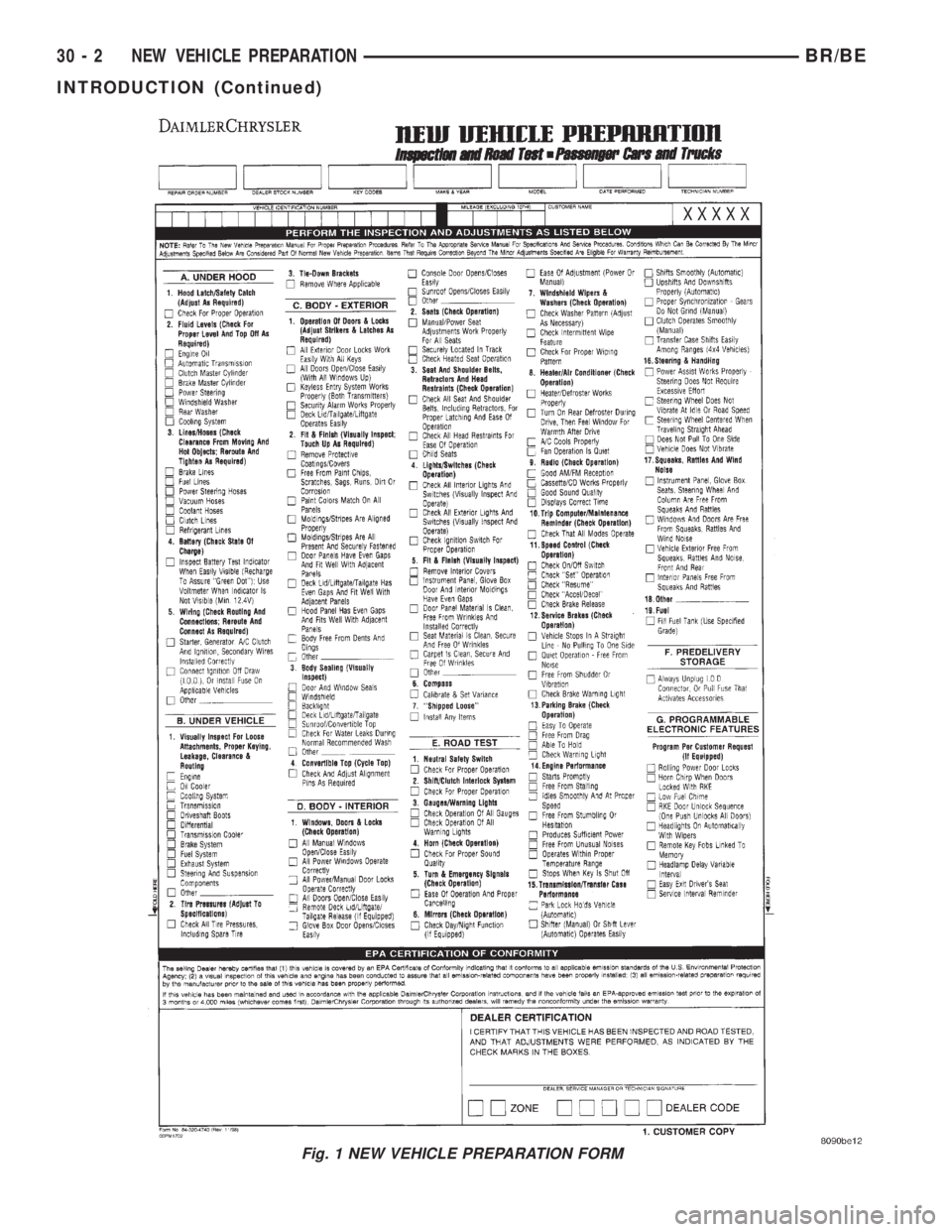
Fig. 1 NEW VEHICLE PREPARATION FORM
30 - 2 NEW VEHICLE PREPARATIONBR/BE
INTRODUCTION (Continued)
Page 2828 of 2889
Items found requiring adjustment and/or repair
should be corrected before delivery of the vehicle.
NOTE: It is the dealer's responsibility to protect
new vehicles from damage and deterioration prior
to retail delivery both before and after new vehicle
preparation.
The information includes the following features:
Inspection points are cross-referenced to the New
Vehicle Preparation Form as follows:
²Titles indicate the general area being inspected
or the types of checks being made (i.e., underhood,
body-exterior, road test, etc.).
²Sub-Titles identify the types of items to be
inspected in that area (i.e., lines/hoses, wiring, etc.).
Procedures follow a logical order to prevent dupli-
cation and wasted effort.
Tips to help you do a better job are found as
NOTES.
RECEIVING
INSPECTION
The following procedures are recommended for
your own protection upon receipt of new vehicles.
When a new car is delivered by the carrier, it should
be inspected to ensure that it is in good condition
and to determine if there is any shortage or transpor-
tation damage.
EXTERIOR
Upon receipt of a new vehicle, check immediately
for:
²Under carriage damage
²Chipped or cracked windshield, broken windows,
and loose or missing moldings and name-plates
²Dents, scrapes, scratches, chips, dirt in paints or
other damage to the body exterior
²Damaged or missing side view mirror(s)
²Missing wheel nuts
²Broken or missing lenses
²Chafing, bruises, cuts, or scrapes on tire side-
walls or tread
²Missing underhood items
²Missing fuel filler cap
²Shipped loose items-license plate bracket, spare
tire, jack and tire wrench, radio antenna, floor mats,
wheel covers, cargo nets, fuses and other items²Ensure that IOD fuse is removed
²Check battery test indicator when easily visible,
or use voltmeter (battery must be at 12.4 volts or
greater). Charge to ensure green dot-visibility, per-
manent damage may occur if battery remains in a
discharged state for any length of time.
INTERIOR
Check interior items such as:
²Rearview mirror
²Accessory control knobs
²Smokers package items
²Keys
²Radio
²Special equipment items listed on shipper
²Owner's Manual and Consumer information Bro-
chures (normally stored in the glove box).
²Cuts, abrasions or stains on interior trim.
NOTE: Remember a careful look at new vehicles
when they are received may prevent problems when
preparing vehicles for delivery to your customers.
MAJOR INSPECTION POINTS
(1) Check operation of hood latch and safety catch-
adjust as required.
(2) Check all fluids for proper level and top off
with the proper fluid as required-engine oil, auto-
matic transmission fluid, brake master cylinder,
clutch master cylinder, power steering, windshield
washer, and cooling system. (Vehicle must be at nor-
mal operating temperature for some of these checks.)
(3) Check brake, clutch, fuel, and power steering
lines and hoses for leaks and clearance from moving
and hot objects-reroute to the proper location and
tighten as required.
(4) Check battery state of charge-recharge if neces-
sary, to ensure green dot is visible or instrument
panel voltmeter indicates 12.4 volts or greater.
(5) Check routing and connections of underhood
wiring, vacuum hoses, refrigerant lines and coolant
hoses for leaks, loose connections and clearance from
moving objects reroute and tighten connections as
required. Install IOD fuse on applicable vehicles.
NOTE: Reset radio, clock, compass, etc., after
installing, if vehicle is being delivered.
BR/BENEW VEHICLE PREPARATION 30 - 3
INTRODUCTION (Continued)
Page 2829 of 2889
UNDER HOOD
INSPECTION - HOOD LATCH/SAFETY CATCH
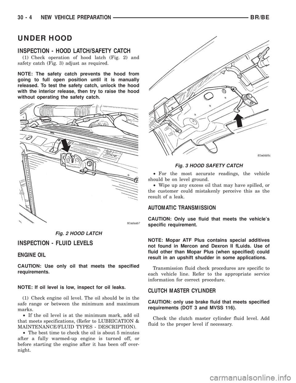
(1) Check operation of hood latch (Fig. 2) and
safety catch (Fig. 3) adjust as required.
NOTE: The safety catch prevents the hood from
going to full open position until it is manually
released. To test the safety catch, unlock the hood
with the interior release, then try to raise the hood
without operating the safety catch.
INSPECTION - FLUID LEVELS
ENGINE OIL
CAUTION: Use only oil that meets the specified
requirements.
NOTE: If oil level is low, inspect for oil leaks.
(1) Check engine oil level. The oil should be in the
safe range or between the minimum and maximum
marks.
²If the oil level is at the minimum mark, add oil
that meets specifications, (Refer to LUBRICATION &
MAINTENANCE/FLUID TYPES - DESCRIPTION).
²The best time to check the oil is about 5 minutes
after a fully warmed-up engine is turned off, or
before starting the engine after it has been off over-
night.²For the most accurate readings, the vehicle
should be on level ground.
²Wipe up any excess oil that may have spilled, or
the customer could mistakenly perceive this as the
result of a leak.
AUTOMATIC TRANSMISSION
CAUTION: Only use fluid that meets the vehicle's
specific requirement.
NOTE: Mopar ATF Plus contains special additives
not found in Mercon and Dexron II fLuids. Use of
fluid other than Mopar Plus (when specified) could
result in an upshift shudder in some applications.
Transmission fluid check procedures are specific to
each vehicle line. Refer to the appropriate service
information for correct procedure.
CLUTCH MASTER CYLINDER
CAUTION: only use brake fluid that meets specified
requirements (DOT 3 and MVSS 116).
Check the clutch master cylinder fluid level. Add
fluid to the proper level if necessary.
Fig. 2 HOOD LATCH
Fig. 3 HOOD SAFETY CATCH
30 - 4 NEW VEHICLE PREPARATIONBR/BE
Page 2830 of 2889
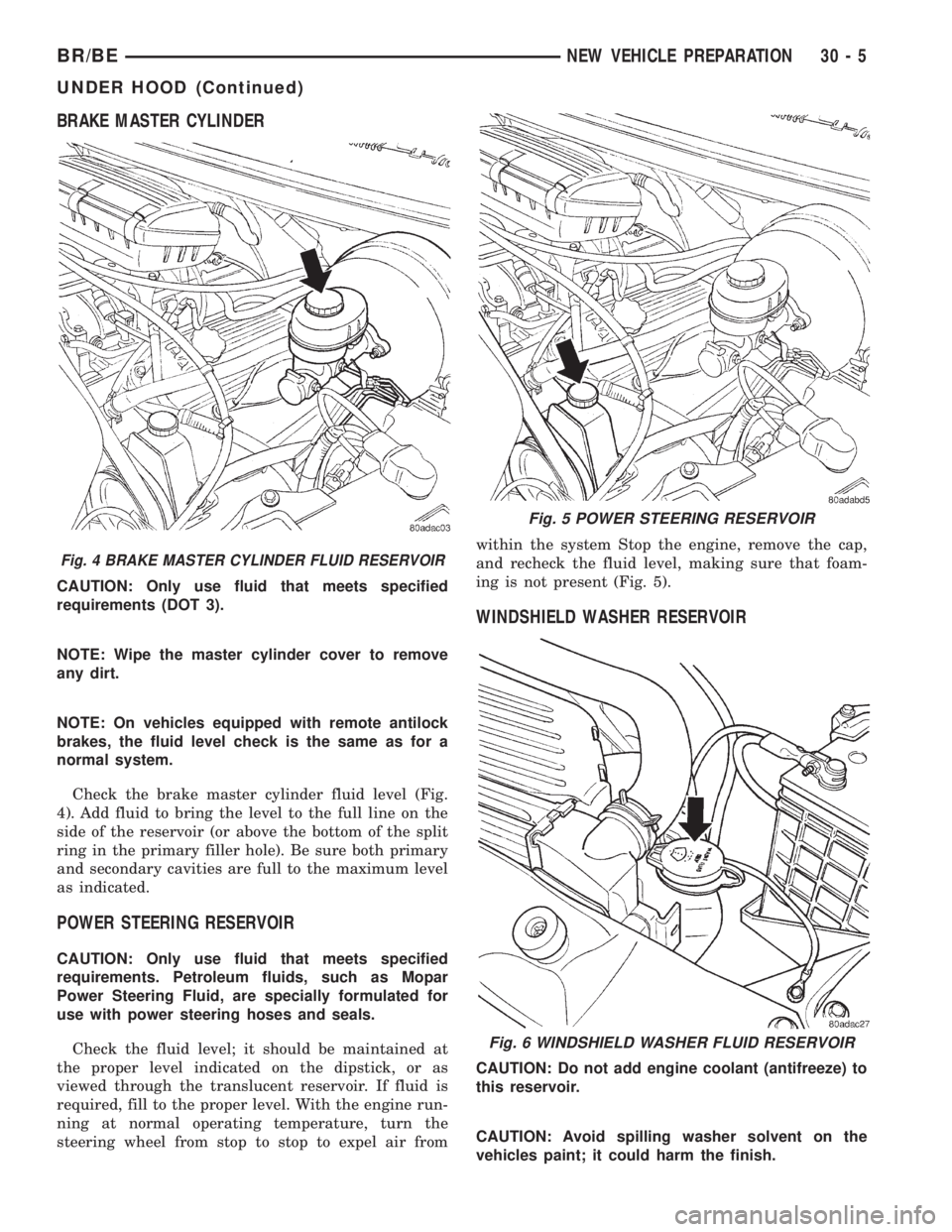
BRAKE MASTER CYLINDER
CAUTION: Only use fluid that meets specified
requirements (DOT 3).
NOTE: Wipe the master cylinder cover to remove
any dirt.
NOTE: On vehicles equipped with remote antilock
brakes, the fluid level check is the same as for a
normal system.
Check the brake master cylinder fluid level (Fig.
4). Add fluid to bring the level to the full line on the
side of the reservoir (or above the bottom of the split
ring in the primary filler hole). Be sure both primary
and secondary cavities are full to the maximum level
as indicated.
POWER STEERING RESERVOIR
CAUTION: Only use fluid that meets specified
requirements. Petroleum fluids, such as Mopar
Power Steering Fluid, are specially formulated for
use with power steering hoses and seals.
Check the fluid level; it should be maintained at
the proper level indicated on the dipstick, or as
viewed through the translucent reservoir. If fluid is
required, fill to the proper level. With the engine run-
ning at normal operating temperature, turn the
steering wheel from stop to stop to expel air fromwithin the system Stop the engine, remove the cap,
and recheck the fluid level, making sure that foam-
ing is not present (Fig. 5).
WINDSHIELD WASHER RESERVOIR
CAUTION: Do not add engine coolant (antifreeze) to
this reservoir.
CAUTION: Avoid spilling washer solvent on the
vehicles paint; it could harm the finish.
Fig. 4 BRAKE MASTER CYLINDER FLUID RESERVOIR
Fig. 5 POWER STEERING RESERVOIR
Fig. 6 WINDSHIELD WASHER FLUID RESERVOIR
BR/BENEW VEHICLE PREPARATION 30 - 5
UNDER HOOD (Continued)