DODGE RAM 2001 Service Repair Manual
Manufacturer: DODGE, Model Year: 2001, Model line: RAM, Model: DODGE RAM 2001Pages: 2889, PDF Size: 68.07 MB
Page 2811 of 2889
AIR FLOW
The ECM cannot detect a clogged, restricted or
dirty air filter element, or a restriction in the air
inlet system. However, these could result in a possi-
ble misfire which may set a DTC.
AIR PRESSURE LEAKS
The ECM cannot detect leaks or restrictions in the
air intake system. However, these could cause the
ECM to store a Manifold Air Pressure (MAP) sensor
DTC (boost pressure problem detected).PCM/ECM SYSTEM GROUNDS
The PCM/ECM cannot directly determine poor sys-
tem grounds. However, one or more DTC's may be
generated as a result of poor grounds.
PCM/ECM CONNECTOR ENGAGEMENT
The PCM/ECM may not be able to determine
spread, damaged or corroded connector pins. How-
ever, it might store DTC's as a result of spread con-
nector pins (circuits that are open).
25 - 24 EMISSIONS CONTROLBR/BE
EMISSIONS CONTROL (Continued)
Page 2812 of 2889
AIR INJECTION
TABLE OF CONTENTS
page page
AIR INJECTION
DESCRIPTION...........................25
OPERATION.............................27
SPECIFICATIONS........................28
AIR INJECTION PUMP
DESCRIPTION...........................28
OPERATION.............................28
DIAGNOSIS AND TESTING.................28
AIR INJECTION PUMP...................28
REMOVAL..............................29
INSTALLATION...........................29AIR PUMP FILTER
REMOVAL..............................29
INSTALLATION...........................29
ONE WAY CHECK VALVE
DESCRIPTION...........................30
OPERATION.............................30
DIAGNOSIS AND TESTING.................30
TESTING ONE-WAY CHECK VALVE.........30
REMOVAL..............................30
INSTALLATION...........................30
AIR INJECTION
DESCRIPTION - AIR INJECTION SYSTEM
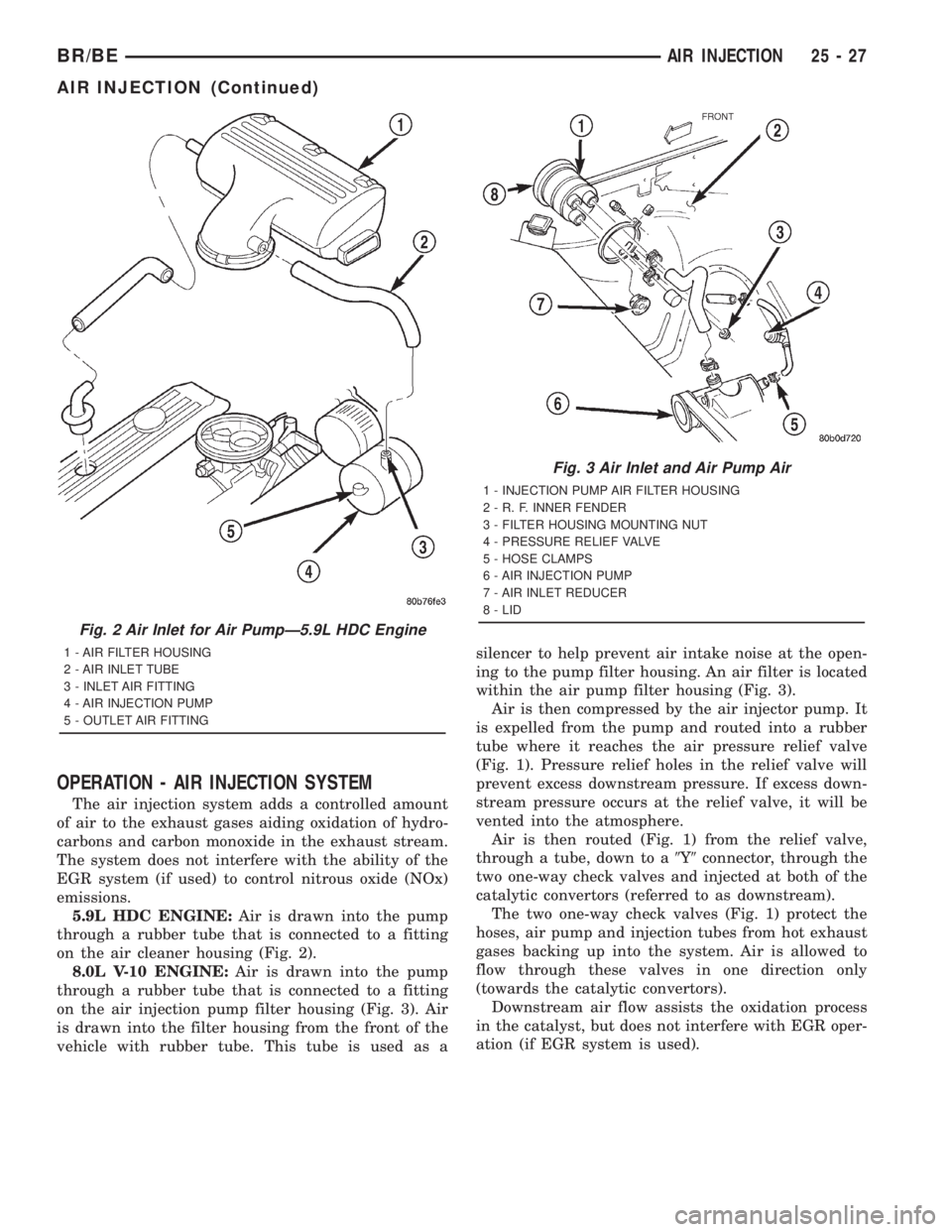
The air injection system (Fig. 1), (Fig. 2) or (Fig. 3)
is used on 5.9L V-8 and 8.0L V-10 heavy duty cycle
(HDC) gas powered engines only. The air injection
system consists of:²A belt-driven air injection (AIR) pump
²Two air pressure relief valves
²Rubber connecting air injection hoses with
clamps
²Metal connecting air tubes
²Two one-way check valves
²A replaceable injection pump air filter (8.0L V-10
engine only)
BR/BEAIR INJECTION 25 - 25
Page 2813 of 2889
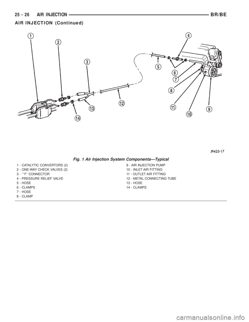
Fig. 1 Air Injection System ComponentsÐTypical
1 - CATALYTIC CONVERTORS (2)
2 - ONE-WAY CHECK VALVES (2)
3-88Y'' CONNECTOR
4 - PRESSURE RELIEF VALVE
5 - HOSE
6 - CLAMPS
7 - HOSE
8 - CLAMP9 - AIR INJECTION PUMP
10 - INLET AIR FITTING
11 - OUTLET AIR FITTING
12 - METAL CONNECTING TUBE
13 - HOSE
14 - CLAMPS
25 - 26 AIR INJECTIONBR/BE
AIR INJECTION (Continued)
Page 2814 of 2889
OPERATION - AIR INJECTION SYSTEM
The air injection system adds a controlled amount
of air to the exhaust gases aiding oxidation of hydro-
carbons and carbon monoxide in the exhaust stream.
The system does not interfere with the ability of the
EGR system (if used) to control nitrous oxide (NOx)
emissions.
5.9L HDC ENGINE:Air is drawn into the pump
through a rubber tube that is connected to a fitting
on the air cleaner housing (Fig. 2).
8.0L V-10 ENGINE:Air is drawn into the pump
through a rubber tube that is connected to a fitting
on the air injection pump filter housing (Fig. 3). Air
is drawn into the filter housing from the front of the
vehicle with rubber tube. This tube is used as asilencer to help prevent air intake noise at the open-
ing to the pump filter housing. An air filter is located
within the air pump filter housing (Fig. 3).
Air is then compressed by the air injector pump. It
is expelled from the pump and routed into a rubber
tube where it reaches the air pressure relief valve
(Fig. 1). Pressure relief holes in the relief valve will
prevent excess downstream pressure. If excess down-
stream pressure occurs at the relief valve, it will be
vented into the atmosphere.
Air is then routed (Fig. 1) from the relief valve,
through a tube, down to a9Y9connector, through the
two one-way check valves and injected at both of the
catalytic convertors (referred to as downstream).
The two one-way check valves (Fig. 1) protect the
hoses, air pump and injection tubes from hot exhaust
gases backing up into the system. Air is allowed to
flow through these valves in one direction only
(towards the catalytic convertors).
Downstream air flow assists the oxidation process
in the catalyst, but does not interfere with EGR oper-
ation (if EGR system is used).
Fig. 2 Air Inlet for Air PumpÐ5.9L HDC Engine
1 - AIR FILTER HOUSING
2 - AIR INLET TUBE
3 - INLET AIR FITTING
4 - AIR INJECTION PUMP
5 - OUTLET AIR FITTING
Fig. 3 Air Inlet and Air Pump Air
1 - INJECTION PUMP AIR FILTER HOUSING
2 - R. F. INNER FENDER
3 - FILTER HOUSING MOUNTING NUT
4 - PRESSURE RELIEF VALVE
5 - HOSE CLAMPS
6 - AIR INJECTION PUMP
7 - AIR INLET REDUCER
8 - LID
BR/BEAIR INJECTION 25 - 27
AIR INJECTION (Continued)
Page 2815 of 2889
SPECIFICATIONS
TORQUE - AIR INJECTION SYSTEM
DESCRIPTION N´m Ft. Lbs. In. Lbs.
Air Pump Filter Housing
Nut18
Air Pump Mounting Bolts 40 30
Air Pump Pulley Mounting
Bolts11 105
One-Way Check Valve to
Catalyst Tube33 25
AIR INJECTION PUMP
DESCRIPTION
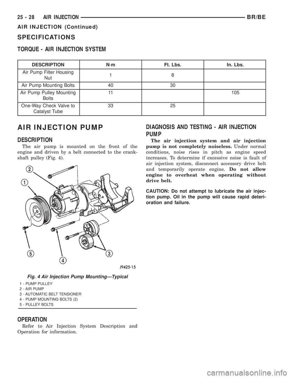
The air pump is mounted on the front of the
engine and driven by a belt connected to the crank-
shaft pulley (Fig. 4).
OPERATION
Refer to Air Injection System Description and
Operation for information.
DIAGNOSIS AND TESTING - AIR INJECTION
PUMP
The air injection system and air injection
pump is not completely noiseless.Under normal
conditions, noise rises in pitch as engine speed
increases. To determine if excessive noise is fault of
air injection system, disconnect accessory drive belt
and temporarily operate engine.Do not allow
engine to overheat when operating without
drive belt.
CAUTION: Do not attempt to lubricate the air injec-
tion pump. Oil in the pump will cause rapid deteri-
oration and failure.
Fig. 4 Air Injection Pump MountingÐTypical
1 - PUMP PULLEY
2 - AIR PUMP
3 - AUTOMATIC BELT TENSIONER
4 - PUMP MOUNTING BOLTS (2)
5 - PULLEY BOLTS
25 - 28 AIR INJECTIONBR/BE
AIR INJECTION (Continued)
Page 2816 of 2889
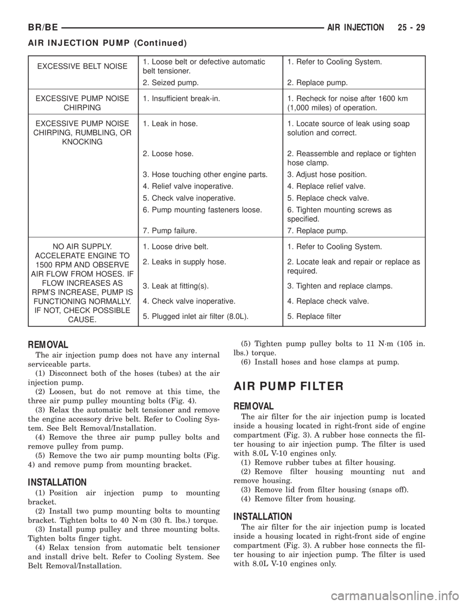
EXCESSIVE BELT NOISE1. Loose belt or defective automatic
belt tensioner.1. Refer to Cooling System.
2. Seized pump. 2. Replace pump.
EXCESSIVE PUMP NOISE
CHIRPING1. Insufficient break-in. 1. Recheck for noise after 1600 km
(1,000 miles) of operation.
EXCESSIVE PUMP NOISE
CHIRPING, RUMBLING, OR
KNOCKING1. Leak in hose. 1. Locate source of leak using soap
solution and correct.
2. Loose hose. 2. Reassemble and replace or tighten
hose clamp.
3. Hose touching other engine parts. 3. Adjust hose position.
4. Relief valve inoperative. 4. Replace relief valve.
5. Check valve inoperative. 5. Replace check valve.
6. Pump mounting fasteners loose. 6. Tighten mounting screws as
specified.
7. Pump failure. 7. Replace pump.
NO AIR SUPPLY.
ACCELERATE ENGINE TO
1500 RPM AND OBSERVE
AIR FLOW FROM HOSES. IF
FLOW INCREASES AS
RPM'S INCREASE, PUMP IS
FUNCTIONING NORMALLY.
IF NOT, CHECK POSSIBLE
CAUSE.1. Loose drive belt. 1. Refer to Cooling System.
2. Leaks in supply hose. 2. Locate leak and repair or replace as
required.
3. Leak at fitting(s). 3. Tighten and replace clamps.
4. Check valve inoperative. 4. Replace check valve.
5. Plugged inlet air filter (8.0L). 5. Replace filter
REMOVAL
The air injection pump does not have any internal
serviceable parts.
(1) Disconnect both of the hoses (tubes) at the air
injection pump.
(2) Loosen, but do not remove at this time, the
three air pump pulley mounting bolts (Fig. 4).
(3) Relax the automatic belt tensioner and remove
the engine accessory drive belt. Refer to Cooling Sys-
tem. See Belt Removal/Installation.
(4) Remove the three air pump pulley bolts and
remove pulley from pump.
(5) Remove the two air pump mounting bolts (Fig.
4) and remove pump from mounting bracket.
INSTALLATION
(1) Position air injection pump to mounting
bracket.
(2) Install two pump mounting bolts to mounting
bracket. Tighten bolts to 40 N´m (30 ft. lbs.) torque.
(3) Install pump pulley and three mounting bolts.
Tighten bolts finger tight.
(4) Relax tension from automatic belt tensioner
and install drive belt. Refer to Cooling System. See
Belt Removal/Installation.(5) Tighten pump pulley bolts to 11 N´m (105 in.
lbs.) torque.
(6) Install hoses and hose clamps at pump.
AIR PUMP FILTER
REMOVAL
The air filter for the air injection pump is located
inside a housing located in right-front side of engine
compartment (Fig. 3). A rubber hose connects the fil-
ter housing to air injection pump. The filter is used
with 8.0L V-10 engines only.
(1) Remove rubber tubes at filter housing.
(2) Remove filter housing mounting nut and
remove housing.
(3) Remove lid from filter housing (snaps off).
(4) Remove filter from housing.
INSTALLATION
The air filter for the air injection pump is located
inside a housing located in right-front side of engine
compartment (Fig. 3). A rubber hose connects the fil-
ter housing to air injection pump. The filter is used
with 8.0L V-10 engines only.
BR/BEAIR INJECTION 25 - 29
AIR INJECTION PUMP (Continued)
Page 2817 of 2889
(1) Clean inside of housing and lid before install-
ing new filter.
(2) Install filter into housing.
(3) Install lid to filter housing (snaps on).
(4) Position filter housing to fender.
(5) Install mounting nut and tighten to 11 N´m (8
ft. lbs.) torque.
(6) Install rubber tubes and cap at filter housing.
ONE WAY CHECK VALVE
DESCRIPTION
For air injection systems:A pair of one-way
check valves is used with the air injection system.
The check valves (Fig. 1) are located on each of the
air injection downstream tubes.
OPERATION
Each one-way check valve has a one-way dia-
phragm which prevents hot exhaust gases from back-
ing up into the air injection hose and air injection
pump. The check valve will protect the system if the
air injection pump belt fails, an air hose ruptures or
exhaust system pressure becomes abnormally high.
DIAGNOSIS AND TESTING - ONE-WAY CHECK
VALVE
The one-way check valves are not repairable. To
determine condition of valve, remove the rubber air
tube from the inlet side of each check valve. Start the
engine. If exhaust gas is escaping through the inlet
side of check valve, it must be replaced.
REMOVAL
(1) Remove the hose clamp at inlet side of valve.
(2) Remove hose from valve.
(3) Remove valve from catalyst tube (unscrew).To
prevent damage to catalyst tube, a backup
wrench must be used on the tube.
INSTALLATION
(1) Install valve to catalyst tube. Tighten to 33
N´m (25 ft. lbs.) torque.
(2) Install hose and hose clamp to valve.
25 - 30 AIR INJECTIONBR/BE
AIR PUMP FILTER (Continued)
Page 2818 of 2889
EVAPORATIVE EMISSIONS
TABLE OF CONTENTS
page page
EVAPORATIVE EMISSIONS
DESCRIPTION...........................31
SPECIFICATIONS........................31
CCV HOSE
DESCRIPTION...........................32
OPERATION.............................32
CRANKCASE VENT HOSE
DESCRIPTION...........................32
EVAP/PURGE SOLENOID
DESCRIPTION...........................32
REMOVAL..............................32
INSTALLATION...........................32
FUEL FILLER CAP
DESCRIPTION...........................33
OPERATION.............................33
REMOVAL..............................33
LEAK DETECTION PUMP
DESCRIPTION...........................33REMOVAL..............................34
INSTALLATION...........................34
PCV FILTER
DESCRIPTION...........................35
P C V VA LV E
DESCRIPTION...........................35
OPERATION.............................35
DIAGNOSIS AND TESTING.................36
PCV VALVE TEST - 3.9/5.2/5.9L ENGINE.....36
VACUUM LINES
DIAGNOSIS AND TESTING.................37
VACUUM SCHEMATICS..................37
VAPOR CANISTER
DESCRIPTION...........................37
OPERATION.............................37
REMOVAL..............................37
INSTALLATION...........................38
EVAPORATIVE EMISSIONS
DESCRIPTION - EVAP SYSTEM
The evaporation control system prevents the emis-
sion of fuel tank vapors into the atmosphere. When
fuel evaporates in the fuel tank, the vapors pass
through vent hoses or tubes into the two charcoal
filled evaporative canisters. The canisters tempo-
rarily hold the vapors. The Powertrain Control Mod-
ule (PCM) allows intake manifold vacuum to draw
vapors into the combustion chambers during certain
operating conditions.
All 3.9L/5.2L/5.9L/8.0L gasoline powered engines
use a duty cycle purge system. The PCM controlsvapor flow by operating the duty cycle EVAP purge
solenoid. Refer to Duty Cycle EVAP Canister Purge
Solenoid for additional information.
When equipped with certain emissions packages, a
Leak Detection Pump (LDP) will be used as part of
the evaporative system. This pump is used as part of
OBD II requirements. Refer to Leak Detection Pump
in this group for additional information.
NOTE: The hoses used in this system are specially
manufactured. If replacement becomes necessary, it
is important to use only fuel resistant hose.
SPECIFICATIONS
TORQUE - EVAP SYSTEM
DESCRIPTION N´m Ft. Lbs. In. Lbs.
EVAP Canister Mounting Nuts 9 80
Leak Detection Pump Mounting Screws 1 11
Leak Detection Pump Filter Mounting
Bolt765
BR/BEEVAPORATIVE EMISSIONS 25 - 31
Page 2819 of 2889
CCV HOSE
DESCRIPTION - 8.0L
The 8.0L V-10 engine is equipped with a Crankcase
Ventilation (CCV) system. The CCV system performs
the same function as a conventional PCV system, but
does not use a vacuum controlled valve (PCV valve).
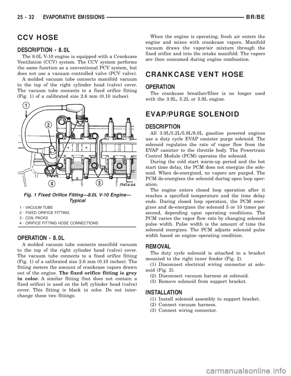
A molded vacuum tube connects manifold vacuum
to the top of the right cylinder head (valve) cover.
The vacuum tube connects to a fixed orifice fitting
(Fig. 1) of a calibrated size 2.6 mm (0.10 inches).
OPERATION - 8.0L
A molded vacuum tube connects manifold vacuum
to the top of the right cylinder head (valve) cover.
The vacuum tube connects to a fixed orifice fitting
(Fig. 1) of a calibrated size 2.6 mm (0.10 inches). The
fitting meters the amount of crankcase vapors drawn
out of the engine.The fixed orifice fitting is grey
in color.A similar fitting (but does not contain a
fixed orifice) is used on the left cylinder head (valve)
cover. This fitting is black in color. Do not inter-
change these two fittings.When the engine is operating, fresh air enters the
engine and mixes with crankcase vapors. Manifold
vacuum draws the vapor/air mixture through the
fixed orifice and into the intake manifold. The vapors
are then consumed during engine combustion.
CRANKCASE VENT HOSE
OPERATION
The crankcase breather/filter is no longer used
with the 3.9L, 5.2L or 5.9L engine.
EVAP/PURGE SOLENOID
DESCRIPTION
All 3.9L/5.2L/5.9L/8.0L gasoline powered engines
use a duty cycle EVAP canister purge solenoid. The
solenoid regulates the rate of vapor flow from the
EVAP canister to the throttle body. The Powertrain
Control Module (PCM) operates the solenoid.
During the cold start warm-up period and the hot
start time delay, the PCM does not energize the sole-
noid. When de-energized, no vapors are purged. The
PCM de-energizes the solenoid during open loop oper-
ation.
The engine enters closed loop operation after it
reaches a specified temperature and the time delay
ends. During closed loop operation, the PCM ener-
gizes and de-energizes the solenoid 5 or 10 times per
second, depending upon operating conditions. The
PCM varies the vapor flow rate by changing solenoid
pulse width. Pulse width is the amount of time the
solenoid energizes. The PCM adjusts solenoid pulse
width based on engine operating condition.
REMOVAL
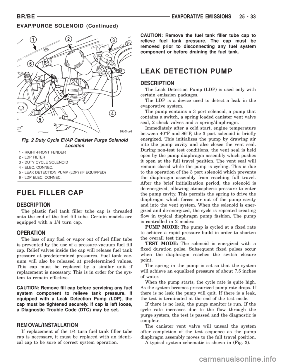
The duty cycle solenoid is attached to a bracket
mounted to the right inner fender (Fig. 2).
(1) Disconnect electrical wiring connector at sole-
noid (Fig. 2).
(2) Disconnect vacuum harness at solenoid.
(3) Remove solenoid from support bracket.
INSTALLATION
(1) Install solenoid assembly to support bracket.
(2) Connect vacuum harness.
(3) Connect wiring connector.
Fig. 1 Fixed Orifice FittingÐ8.0L V-10 EngineÐ
Typical
1 - VACUUM TUBE
2 - FIXED ORIFICE FITTING
3 - COIL PACKS
4 - ORIFICE FITTING HOSE CONNECTIONS
25 - 32 EVAPORATIVE EMISSIONSBR/BE
Page 2820 of 2889
FUEL FILLER CAP
DESCRIPTION
The plastic fuel tank filler tube cap is threaded
onto the end of the fuel fill tube. Certain models are
equipped with a 1/4 turn cap.
OPERATION
The loss of any fuel or vapor out of fuel filler tube
is prevented by the use of a pressure-vacuum fuel fill
cap. Relief valves inside the cap will release fuel tank
pressure at predetermined pressures. Fuel tank vac-
uum will also be released at predetermined values.
This cap must be replaced by a similar unit if
replacement is necessary. This is in order for the sys-
tem to remain effective.
CAUTION: Remove fill cap before servicing any fuel
system component to relieve tank pressure. If
equipped with a Leak Detection Pump (LDP), the
cap must be tightened securely. If cap is left loose,
a Diagnostic Trouble Code (DTC) may be set.
REMOVAL/INSTALLATION
If replacement of the 1/4 turn fuel tank filler tube
cap is necessary, it must be replaced with an identi-
cal cap to be sure of correct system operation.CAUTION: Remove the fuel tank filler tube cap to
relieve fuel tank pressure. The cap must be
removed prior to disconnecting any fuel system
component or before draining the fuel tank.
LEAK DETECTION PUMP
DESCRIPTION
The Leak Detection Pump (LDP) is used only with
certain emission packages.
The LDP is a device used to detect a leak in the
evaporative system.
The pump contains a 3 port solenoid, a pump that
contains a switch, a spring loaded canister vent valve
seal, 2 check valves and a spring/diaphragm.
Immediately after a cold start, engine temperature
between 40ÉF and 86ÉF, the 3 port solenoid is briefly
energized. This initializes the pump by drawing air
into the pump cavity and also closes the vent seal.
During non-test test conditions, the vent seal is held
open by the pump diaphragm assembly which pushes
it open at the full travel position. The vent seal will
remain closed while the pump is cycling. This is due
to the operation of the 3 port solenoid which prevents
the diaphragm assembly from reaching full travel.
After the brief initialization period, the solenoid is
de-energized, allowing atmospheric pressure to enter
the pump cavity. This permits the spring to drive the
diaphragm which forces air out of the pump cavity
and into the vent system. When the solenoid is ener-
gized and de-energized, the cycle is repeated creating
flow in typical diaphragm pump fashion. The pump
is controlled in 2 modes:
PUMP MODE:The pump is cycled at a fixed rate
to achieve a rapid pressure build in order to shorten
the overall test time.
TEST MODE:The solenoid is energized with a
fixed duration pulse. Subsequent fixed pulses occur
when the diaphragm reaches the switch closure
point.
The spring in the pump is set so that the system
will achieve an equalized pressure of about 7.5 inches
of water.
When the pump starts, the cycle rate is quite high.
As the system becomes pressurized pump rate drops. If
there is no leak the pump will quit. If there is a leak,
the test is terminated at the end of the test mode.
If there is no leak, the purge monitor is run. If the
cycle rate increases due to the flow through the
purge system, the test is passed and the diagnostic is
complete.
The canister vent valve will unseal the system
after completion of the test sequence as the pump
diaphragm assembly moves to the full travel position.
A typical system schematic is shown in (Fig. 3).
Fig. 2 Duty Cycle EVAP Canister Purge Solenoid
Location
1 - RIGHT-FRONT FENDER
2 - LDP FILTER
3 - DUTY CYCLE SOLENOID
4 - ELEC. CONNEC.
5 - LEAK DETECTION PUMP (LDP) (IF EQUIPPED)
6 - LDP ELEC. CONNEC.
BR/BEEVAPORATIVE EMISSIONS 25 - 33
EVAP/PURGE SOLENOID (Continued)