DODGE RAM 2001 Service Repair Manual
Manufacturer: DODGE, Model Year: 2001, Model line: RAM, Model: DODGE RAM 2001Pages: 2889, PDF Size: 68.07 MB
Page 451 of 2889

Page 452 of 2889
ELECTRONIC CONTROL MODULES
TABLE OF CONTENTS
page page
BODY CONTROL/CENTRAL TIMER MODULE
DESCRIPTION............................1
OPERATION.............................3
DIAGNOSIS AND TESTING..................4
CENTRAL TIMER MODULE................4
REMOVAL...............................5
INSTALLATION............................6
COMMUNICATION
DESCRIPTION............................6
OPERATION.............................7
DIAGNOSIS AND TESTING.................11
CCDDATABUS ........................11
CONTROLLER ANTILOCK BRAKE
DESCRIPTION...........................11
OPERATION.............................11REMOVAL..............................12
INSTALLATION...........................12
DATA LINK CONNECTOR
DESCRIPTION...........................12
OPERATION.............................12
ENGINE CONTROL MODULE
DESCRIPTION...........................13
OPERATION.............................13
REMOVAL..............................14
INSTALLATION...........................14
POWERTRAIN CONTROL MODULE
DESCRIPTION...........................14
OPERATION.............................17
REMOVAL..............................19
INSTALLATION...........................20
BODY CONTROL/CENTRAL
TIMER MODULE
DESCRIPTION
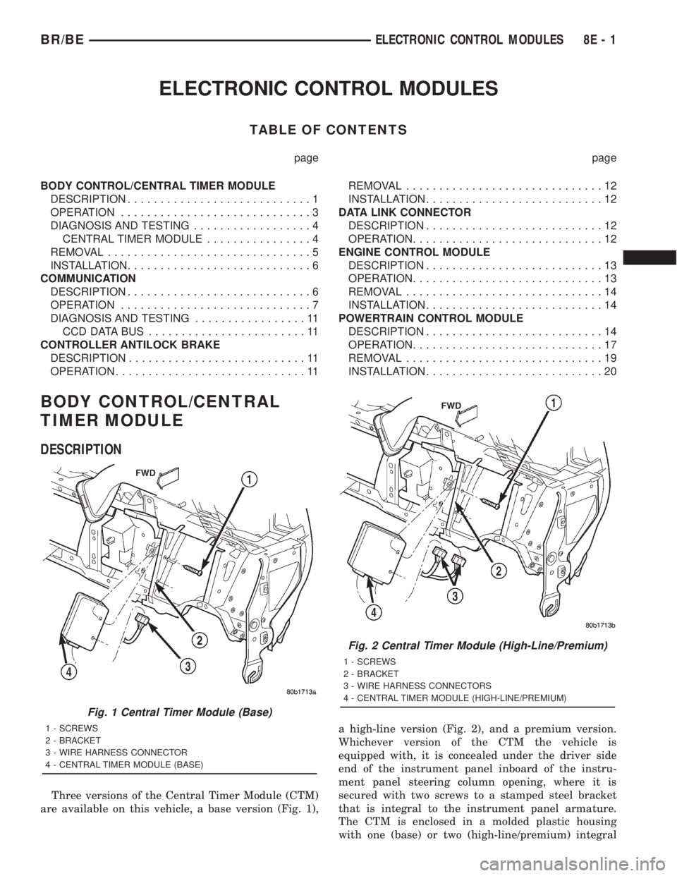
Three versions of the Central Timer Module (CTM)
are available on this vehicle, a base version (Fig. 1),a high-line version (Fig. 2), and a premium version.
Whichever version of the CTM the vehicle is
equipped with, it is concealed under the driver side
end of the instrument panel inboard of the instru-
ment panel steering column opening, where it is
secured with two screws to a stamped steel bracket
that is integral to the instrument panel armature.
The CTM is enclosed in a molded plastic housing
with one (base) or two (high-line/premium) integral
Fig. 1 Central Timer Module (Base)
1 - SCREWS
2 - BRACKET
3 - WIRE HARNESS CONNECTOR
4 - CENTRAL TIMER MODULE (BASE)
Fig. 2 Central Timer Module (High-Line/Premium)
1 - SCREWS
2 - BRACKET
3 - WIRE HARNESS CONNECTORS
4 - CENTRAL TIMER MODULE (HIGH-LINE/PREMIUM)
BR/BEELECTRONIC CONTROL MODULES 8E - 1
Page 453 of 2889
external connector receptacles that connect it to the
vehicle electrical system through one (base) or two
(high-line/premium) take outs with connectors from
the instrument panel wire harness.
The base version of the CTM is used on base mod-
els of this vehicle. It is also sometimes referred to as
the Integrated Electronic Module (IEM). The base
version of the CTM combines the functions of a
chime module and an intermittent wipe module in a
single unit. The high-line version of the CTM is used
on high-line vehicles. The high-line CTM provides all
of the functions of the base version of the CTM, but
also is used to control and integrate many additional
electronic functions and features included on high-
line models. The premium version of the CTM is the
same as the high-line version, but is used only on
models equipped with the heated seat option.
The high-line and premium versions of the CTM
utilize integrated circuitry and information carried
on the Chrysler Collision Detection (CCD) data bus
network along with many hard wired inputs to mon-
itor many sensor and switch inputs throughout the
vehicle. In response to those inputs, the internal cir-
cuitry and programming of the CTM allow it to con-
trol and integrate many electronic functions and
features of the vehicle through both hard wired out-
puts and the transmission of electronic message out-
puts to other electronic modules in the vehicle over
the CCD data bus.
The features that the CTM supports or controls
include the following:
²Automatic Door Lock- The high-line/premium
CTM provides an optional automatic door lock fea-
ture (also known as rolling door locks). This is a pro-
grammable feature.
²Central Locking- The high-line/premium CTM
provides an optional central locking/unlocking fea-
ture.
²Chimes- All versions of the CTM provide chime
service through an integral chime tone generator.
²Courtesy Lamps- The high-line/premium CTM
provides courtesy lamp control with timed load shed-
ding.
²Door Lock Inhibit- The high-line/premium
CTM provides a door lock inhibit feature.
²Enhanced Accident Response- The high-line/
premium CTM provides an optional enhanced acci-
dent response feature. This is a programmable
feature.
²Heated Seats- The premium CTM controls the
optional heated seat system by controlling the opera-
tion of the heated seat relay.
²Illuminated Entry- The high-line/premium
CTM provides a timed illuminated entry feature.²Intermittent Wipe Control- All versions of
the CTM provide control of the intermittent wipe
delay, and wipe-after-wash features.
²Panic Mode- The high-line/premium CTM pro-
vides support for the optional RKE system panic
mode features.
²Power Lock Control- The high-line/premium
CTM provides the optional power lock system fea-
tures, including support for the automatic door lock
and door lock inhibit modes.
²Programmable Features- The high-line/pre-
mium CTM provides support for certain programma-
ble features.
²Remote Keyless Entry- The high-line/pre-
mium CTM provides the optional Remote Keyless
Entry (RKE) system features, including support for
the RKE Lock (with optional horn chirp), Unlock,
Panic, and illuminated entry modes, as well as the
ability to be programmed to recognize up to four
RKE transmitters. The RKE horn chirp is a program-
mable feature.
²Remote Radio Switch Interface- The high-
line/premium CTM monitors and transmits the sta-
tus of the optional remote radio switches.
²Speed Sensitive Intermittent Wipe Control-
The high-line/premium CTM provides the speed sen-
sitive intermittent wipe feature.
²Vehicle Theft Alarm- The high-line/premium
CTM provides control of the optional Vehicle Theft
Alarm features, including support for the central
locking/unlocking mode.
Hard wired circuitry connects the CTM to the elec-
trical system of the vehicle. These hard wired circuits
are integral to several wire harnesses, which are
routed throughout the vehicle and retained by many
different methods. These circuits may be connected to
each other, to the vehicle electrical system and to the
CTM through the use of a combination of soldered
splices, splice block connectors, and many different
types of wire harness terminal connectors and insu-
lators. Refer to the appropriate wiring information.
The wiring information includes wiring diagrams,
proper wire and connector repair procedures, further
details on wire harness routing and retention, as well
as pin-out and location views for the various wire
harness connectors, splices and grounds.
All versions of the CTM for this model are serviced
only as a complete unit. Many of the electronic fea-
tures in the vehicle controlled or supported by the
high-line or premium versions of the CTM are pro-
grammable using the DRBIIItscan tool. In addition,
the high-line/premium CTM software is Flash com-
patible, which means it can be reprogrammed using
Flash reprogramming procedures. However, if any of
the CTM hardware components are damaged or
faulty, the entire CTM unit must be replaced. The
8E - 2 ELECTRONIC CONTROL MODULESBR/BE
BODY CONTROL/CENTRAL TIMER MODULE (Continued)
Page 454 of 2889
base version of the CTM and the hard wired inputs
or outputs of all CTM versions can be diagnosed
using conventional diagnostic tools and methods;
however, for diagnosis of the high-line or premium
versions of the CTM or the CCD data bus, the use of
a DRBIIItscan tool is required. Refer to the appro-
priate diagnostic information.
OPERATION
The Central Timer Module (CTM) is designed to
control and integrate many of the electronic features
and functions of the vehicle. The base version of the
CTM monitors only hard wired inputs and responds
with the proper hard wired outputs. The microproces-
sor-based high-line/premium version of the CTM
monitors many hard wired switch and sensor inputs
as well as those resources it shares with other elec-
tronic modules in the vehicle through its communica-
tion over the Chrysler Collision Detection (CCD) data
bus network. The internal programming and all of
these inputs allow the high-line/premium CTM
microprocessor to determine the tasks it needs to
perform and their priorities, as well as both the stan-
dard and optional features that it should provide.
The high-line/premium CTM programming then per-
forms those tasks and provides those features
through both CCD data bus communication with
other electronic modules and through hard wired out-
puts to a number of circuits, relays, and actuators.
These outputs allow the high-line/premium CTM the
ability to control numerous accessory systems in the
vehicle.
All versions of the CTM operate on battery current
received through fuses in the Junction Block (JB) on
a non-switched fused B(+) circuit, a fused ignition
switch output (st-run) circuit (base version only), and
a fused ignition switch output (run-acc) circuit (high-
line/premium version only). This arrangement allows
the CTM to provide some features regardless of the
ignition switch position, while other features will
operate only with the ignition switch in the Acces-
sory, On, and/or Start positions. All versions of the
CTM are grounded through their connector and take
out of the instrument panel wire harness. The high-
line/premium CTM has another ground received
through a second connector and take out of the
instrument panel wire harness. The first ground cir-
cuit receives ground through a take out with an eye-
let terminal connector of the instrument panel wire
harness that is secured by a nut to a ground stud
located on the left instrument panel end bracket,
while the second ground circuit (high-line/premium
version only) receives ground through a take out with
an eyelet terminal connector of the instrument panel
wire harness that is secured by a nut to a ground
stud located on the back of the instrument panelarmature above the inboard side of the instrument
panel steering column opening.
The high-line/premium CTM monitors its own
internal circuitry as well as many of its input and
output circuits, and will store a Diagnostic Trouble
Code (DTC) in electronic memory for any failure it
detects. These DTCs can be retrieved and diagnosed
using a DRBIIItscan tool. Refer to the appropriate
diagnostic information.
HARD WIRED INPUTS
The hard wired inputs to the CTM include the fol-
lowing:
²CCD bus± - high-line/premium version only
²CCD bus+ - high-line/premium version only
²Cylinder lock switch mux - high-line premium
version only
²Driver door ajar switch sense
²Fused B(+)
²Fused ignition switch output (run-acc) - high-
line/premium version only
²Fused ignition switch output (st-run) - base ver-
sion only
²Ground (one circuit - base version, two circuits -
high-line/premium version)
²Key-in ignition switch sense
²Passenger door ajar switch sense - high-line/pre-
mium version only
²Power door lock motor B(+) lock - high-line/pre-
mium version only
²Power door lock motor B(+) unlock - high-line/
premium version only
²Radio control mux - high-line/premium version
only
²Tone request signal
²Washer switch sense
²Wiper park switch sense
²Wiper switch mode sense
²Wiper switch mode signal
HARD WIRED OUTPUTS
The hard wired outputs of the CTM include the fol-
lowing:
²CCD bus± - high-line/premium version only
²CCD bus+ - high-line/premium version only
²Courtesy lamp switch output - high-line/pre-
mium version only
²Door lock driver - high-line/premium version
only
²Door unlock driver - high-line/premium version
only
²Headlamp relay control - high-line/premium ver-
sion only
²Heated seat relay control - premium version
only
BR/BEELECTRONIC CONTROL MODULES 8E - 3
BODY CONTROL/CENTRAL TIMER MODULE (Continued)
Page 455 of 2889
²Horn relay control - high-line/premium version
only
²VTSS indicator driver - high-line/premium ver-
sion only
²Wiper motor relay control
MESSAGING
The high-line/premium CTM uses the following
messages received from other electronic modules over
the CCD data bus:
²Airbag Deploy (ACM)
²Charging System Failure (PCM)
²Engine RPM (PCM)
²System Voltage (PCM)
²Vehicle Speed (PCM)
²Voltage Fault (PCM)
The high-line/premium CTM provides the following
messages to other electronic modules over the CCD
data bus:
²Engine Enable (PCM)
²Radio Seek Up (Radio)
²Radio Seek Down (Radio)
²Radio Volume Up (Radio)
²Radio Volume Down (Radio)
²Preset Scan (Radio)
DIAGNOSIS AND TESTING - CENTRAL TIMER
MODULE
The hard wired inputs to and outputs from the
Central Timer Module (CTM) may be diagnosed and
tested using conventional diagnostic tools and meth-
ods. Refer to the appropriate wiring information. The
wiring information includes wiring diagrams, proper
wire and connector repair procedures, further details
on wire harness routing and retention, as well as
pin-out and location views for the various wire har-
ness connectors, splices and grounds.
However, conventional diagnostic methods may not
prove conclusive in the diagnosis of the high-line/pre-
mium CTM. In order to obtain conclusive testing of
the high-line/premium CTM, the Chrysler Collision
Detection (CCD) data bus network and all of the elec-
tronic modules that provide inputs to or receive out-
puts from the CTM must also be checked. The most
reliable, efficient, and accurate means to diagnose
the high-line/premium CTM, the CCD data bus net-
work, and the electronic modules that provide inputs
to or receive outputs from the high-line/premium
CTM requires the use of a DRBIIItscan tool and the
appropriate diagnostic information. The DRBIIIt
scan tool can provide confirmation that the CCD data
bus network is functional, that all of the electronic
modules are sending and receiving the proper mes-
sages over the CCD data bus, and that the CTM is
receiving the proper hard wired inputs and respond-ing with the proper hard wired outputs needed to
perform its many functions.
WARNING: ON VEHICLES EQUIPPED WITH AIR-
BAGS, DISABLE THE AIRBAG SYSTEM BEFORE
ATTEMPTING ANY STEERING WHEEL, STEERING
COLUMN, OR INSTRUMENT PANEL COMPONENT
DIAGNOSIS OR SERVICE. DISCONNECT AND ISO-
LATE THE BATTERY NEGATIVE (GROUND) CABLE,
THEN WAIT TWO MINUTES FOR THE AIRBAG SYS-
TEM CAPACITOR TO DISCHARGE BEFORE PER-
FORMING FURTHER DIAGNOSIS OR SERVICE. THIS
IS THE ONLY SURE WAY TO DISABLE THE AIRBAG
SYSTEM. FAILURE TO TAKE THE PROPER PRE-
CAUTIONS COULD RESULT IN ACCIDENTAL AIR-
BAG DEPLOYMENT AND POSSIBLE PERSONAL
INJURY.
NOTE: The following tests may not prove conclu-
sive in the diagnosis of the high-line or premium
versions of the Central Timer Module (CTM). The
most reliable, efficient, and accurate means to diag-
nose the high-line or premium CTM requires the
use of a DRBIIITscan tool and the appropriate diag-
nostic information.
(1) Check the fused B(+) fuse (Fuse 13 - 10
ampere) in the Junction Block (JB). If OK, go to Step
2. If not OK, repair the shorted circuit or component
as required and replace the faulty fuse.
(2) Check for battery voltage at the fused B(+) fuse
(Fuse 13 - 10 ampere) in the JB. If OK, go to Step 3.
If not OK, repair the open fused B(+) circuit between
the JB and the Power Distribution Center (PDC) as
required.
(3) For a base version CTM, check the fused igni-
tion switch output (st-run) fuse (Fuse 11 - 10 ampere)
in the JB. For a high-line/premium version CTM,
check the fused ignition switch output (run-acc) fuse
(Fuse6-25ampere) in the JB. If OK, go to Step 4. If
not OK, repair the shorted circuit or component as
required and replace the faulty fuse.
(4) Turn the ignition switch to the On position. For
a base version CTM, check for battery voltage at the
fused ignition switch output (st-run) fuse (Fuse 11 -
10 ampere) in the JB. For a high-line/premium ver-
sion CTM, check for battery voltage at the fused igni-
tion switch output (run-acc) fuse (Fuse6-25
ampere) in the JB. If OK, go to Step 5. If not OK,
repair the shorted circuit or component as required
and replace the faulty fuse.
(5) Turn the ignition switch to the Off position.
Disconnect and isolate the battery negative cable.
Remove the CTM from its mounting bracket to access
the CTM wire harness connector(s). Disconnect the
instrument panel wire harness connector(s) for the
8E - 4 ELECTRONIC CONTROL MODULESBR/BE
BODY CONTROL/CENTRAL TIMER MODULE (Continued)
Page 456 of 2889
CTM from the CTM connector receptacle(s). Check
the wire harness connectors and the CTM receptacles
for loose, corroded, or damaged terminals and pins. If
OK, go to Step 6. If not OK, repair as required.
(6) Check for continuity between the ground cir-
cuit cavity of the instrument panel wire harness con-
nector (Connector C1) for the CTM and a good
ground. For the high-line/premium version of the
CTM only, repeat the check between the ground cir-
cuit cavity of the instrument panel wire harness con-
nector (Connector C2) for the CTM and a good
ground. In each case, there should be continuity. If
OK, go to Step 7. If not OK, repair the open ground
circuit(s) to ground as required.
(7) Reconnect the battery negative cable. Check for
battery voltage at the fused B(+) circuit cavity of the
instrument panel wire harness connector (Connector
C1) for the CTM. If OK, go to Step 8. If not OK,
repair the open fused B(+) circuit between the CTM
and the JB as required.
(8) Turn the ignition switch to the On position.
Check for battery voltage at the fused ignition switch
output (st-run) circuit cavity (base version) or fused
ignition switch output (run-acc) circuit cavity (high-
line/premium version) of the instrument panel wire
harness connector (Connector C1) for the CTM. If OK
with a base version CTM, replace the faulty CTM. If
OK with a high-line/premium version CTM, use a
DRBIIItscan tool and the appropriate diagnostic
information to perform further diagnosis of the CTM.
If not OK, repair the open fused ignition switch out-
put circuit between the CTM and the JB.
REMOVAL
WARNING: ON VEHICLES EQUIPPED WITH AIR-
BAGS, DISABLE THE AIRBAG SYSTEM BEFORE
ATTEMPTING ANY STEERING WHEEL, STEERING
COLUMN, OR INSTRUMENT PANEL COMPONENT
DIAGNOSIS OR SERVICE. DISCONNECT AND ISO-
LATE THE BATTERY NEGATIVE (GROUND) CABLE,
THEN WAIT TWO MINUTES FOR THE AIRBAG SYS-
TEM CAPACITOR TO DISCHARGE BEFORE PER-
FORMING FURTHER DIAGNOSIS OR SERVICE. THIS
IS THE ONLY SURE WAY TO DISABLE THE AIRBAG
SYSTEM. FAILURE TO TAKE THE PROPER PRE-
CAUTIONS COULD RESULT IN ACCIDENTAL AIR-
BAG DEPLOYMENT AND POSSIBLE PERSONAL
INJURY.
NOTE: Before replacing a high-line/premium version
Central Timer Module (CTM), use a DRBIIITscan
tool to retrieve the current settings for the CTM pro-
grammable features. Refer to the appropriate diag-
nostic information. These settings should be
duplicated in the replacement high-line/premiumCTM using the DRBIIITscan tool before returning
the vehicle to service.
(1) Disconnect and isolate the battery negative
cable.
(2) Remove the steering column opening cover
from the instrument panel. (Refer to 23 - BODY/IN-
STRUMENT PANEL/STEERING COLUMN OPEN-
ING COVER - REMOVAL).
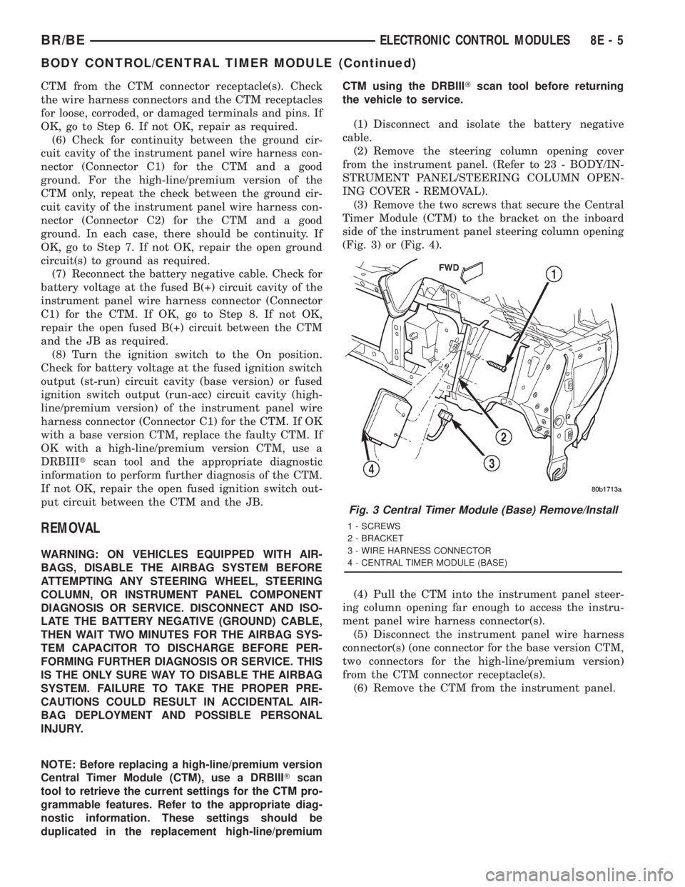
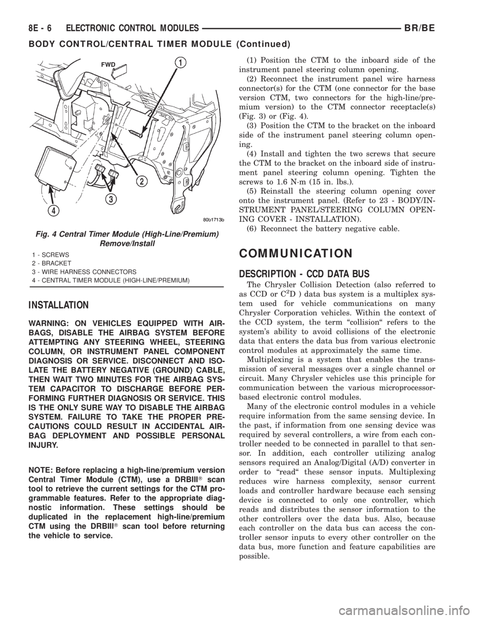
(3) Remove the two screws that secure the Central
Timer Module (CTM) to the bracket on the inboard
side of the instrument panel steering column opening
(Fig. 3) or (Fig. 4).
(4) Pull the CTM into the instrument panel steer-
ing column opening far enough to access the instru-
ment panel wire harness connector(s).
(5) Disconnect the instrument panel wire harness
connector(s) (one connector for the base version CTM,
two connectors for the high-line/premium version)
from the CTM connector receptacle(s).
(6) Remove the CTM from the instrument panel.
Fig. 3 Central Timer Module (Base) Remove/Install
1 - SCREWS
2 - BRACKET
3 - WIRE HARNESS CONNECTOR
4 - CENTRAL TIMER MODULE (BASE)
BR/BEELECTRONIC CONTROL MODULES 8E - 5
BODY CONTROL/CENTRAL TIMER MODULE (Continued)
Page 457 of 2889
INSTALLATION
WARNING: ON VEHICLES EQUIPPED WITH AIR-
BAGS, DISABLE THE AIRBAG SYSTEM BEFORE
ATTEMPTING ANY STEERING WHEEL, STEERING
COLUMN, OR INSTRUMENT PANEL COMPONENT
DIAGNOSIS OR SERVICE. DISCONNECT AND ISO-
LATE THE BATTERY NEGATIVE (GROUND) CABLE,
THEN WAIT TWO MINUTES FOR THE AIRBAG SYS-
TEM CAPACITOR TO DISCHARGE BEFORE PER-
FORMING FURTHER DIAGNOSIS OR SERVICE. THIS
IS THE ONLY SURE WAY TO DISABLE THE AIRBAG
SYSTEM. FAILURE TO TAKE THE PROPER PRE-
CAUTIONS COULD RESULT IN ACCIDENTAL AIR-
BAG DEPLOYMENT AND POSSIBLE PERSONAL
INJURY.
NOTE: Before replacing a high-line/premium version
Central Timer Module (CTM), use a DRBIIITscan
tool to retrieve the current settings for the CTM pro-
grammable features. Refer to the appropriate diag-
nostic information. These settings should be
duplicated in the replacement high-line/premium
CTM using the DRBIIITscan tool before returning
the vehicle to service.(1) Position the CTM to the inboard side of the
instrument panel steering column opening.
(2) Reconnect the instrument panel wire harness
connector(s) for the CTM (one connector for the base
version CTM, two connectors for the high-line/pre-
mium version) to the CTM connector receptacle(s)
(Fig. 3) or (Fig. 4).
(3) Position the CTM to the bracket on the inboard
side of the instrument panel steering column open-
ing.
(4) Install and tighten the two screws that secure
the CTM to the bracket on the inboard side of instru-
ment panel steering column opening. Tighten the
screws to 1.6 N´m (15 in. lbs.).
(5) Reinstall the steering column opening cover
onto the instrument panel. (Refer to 23 - BODY/IN-
STRUMENT PANEL/STEERING COLUMN OPEN-
ING COVER - INSTALLATION).
(6) Reconnect the battery negative cable.
COMMUNICATION
DESCRIPTION - CCD DATA BUS
The Chrysler Collision Detection (also referred to
as CCD or C2D ) data bus system is a multiplex sys-
tem used for vehicle communications on many
Chrysler Corporation vehicles. Within the context of
the CCD system, the term ªcollisionª refers to the
system's ability to avoid collisions of the electronic
data that enters the data bus from various electronic
control modules at approximately the same time.
Multiplexing is a system that enables the trans-
mission of several messages over a single channel or
circuit. Many Chrysler vehicles use this principle for
communication between the various microprocessor-
based electronic control modules.
Many of the electronic control modules in a vehicle
require information from the same sensing device. In
the past, if information from one sensing device was
required by several controllers, a wire from each con-
troller needed to be connected in parallel to that sen-
sor. In addition, each controller utilizing analog
sensors required an Analog/Digital (A/D) converter in
order to ªreadª these sensor inputs. Multiplexing
reduces wire harness complexity, sensor current
loads and controller hardware because each sensing
device is connected to only one controller, which
reads and distributes the sensor information to the
other controllers over the data bus. Also, because
each controller on the data bus can access the con-
troller sensor inputs to every other controller on the
data bus, more function and feature capabilities are
possible.
Fig. 4 Central Timer Module (High-Line/Premium)
Remove/Install
1 - SCREWS
2 - BRACKET
3 - WIRE HARNESS CONNECTORS
4 - CENTRAL TIMER MODULE (HIGH-LINE/PREMIUM)
8E - 6 ELECTRONIC CONTROL MODULESBR/BE
BODY CONTROL/CENTRAL TIMER MODULE (Continued)
Page 458 of 2889
In addition to reducing wire harness complexity,
component sensor current loads and controller hard-
ware, multiplexing offers a diagnostic advantage. A
multiplex system allows the information flowing
between controllers to be monitored using a diagnos-
tic scan tool. The Chrysler system allows an elec-
tronic control module to broadcast message data out
onto the bus where all other electronic control mod-
ules can ªhearº the messages that are being sent.
When a module hears a message on the data bus
that it requires, it relays that message to its micro-
processor. Each module ignores the messages on the
data bus that are being sent to other electronic con-
trol modules.
With a diagnostic scan tool connected into the CCD
circuit, a technician is able to observe many of the
electronic control module function and message out-
puts while; at the same time, controlling many of the
sensor message inputs. The CCD data bus, along
with the use of a diagnostic scan tool and a logic-
based approach to test procedures, as found in the
Diagnostic Procedures manuals, allows the trained
automotive technician to more easily, accurately and
efficiently diagnose the many complex and integrated
electronic functions and features found on today's
vehicles.
OPERATION - CCD DATA BUS
The CCD data bus system was designed to run at a
7812.5 baud rate (or 7812.5 bits per second). In order
to successfully transmit and receive binary messages
over the CCD data bus, the system requires the fol-
lowing:
²Bus (+) and Bus (±) Circuits
²CCD Chips in Each Electronic Control Module
²Bus Bias and Termination
²Bus Messaging
²Bus Message Coding
Following are additional details of each of the
above system requirements.
BUS (+) AND BUS (±) CIRCUITS
The two wires (sometimes referred to as the ªtwist-
ed pairº) that comprise the CCD data bus are the D1
circuit [Bus (+)], and the D2 circuit [Bus (±)]. The9D9
in D1 and D2 identify these as diagnostic circuits.
Transmission and receipt of binary messages on the
CCD data bus is accomplished by cycling the voltage
differential between the Bus (+) and Bus (±) circuits.The two data bus wires are twisted together in
order to shield the wires from the effects of any Elec-
tro-Magnetic Interference (EMI) from switched volt-
age sources. An induced EMI voltage can be
generated in any wire by a nearby switched voltage
or switched ground circuit. By twisting the data bus
wires together, the induced voltage spike (either up
or down) affects both wires equally. Since both wires
are affected equally, a voltage differential still exists
between the Bus (+) and Bus (±) circuits, and the
data bus messages can still be broadcast or received.
The correct specification for data bus wire twisting is
one turn for every 44.45 millimeters (1
3¤4inches) of
wire.
CCD CHIPS
In order for an electronic control module to commu-
nicate on the CCD data bus, it must have a CCD
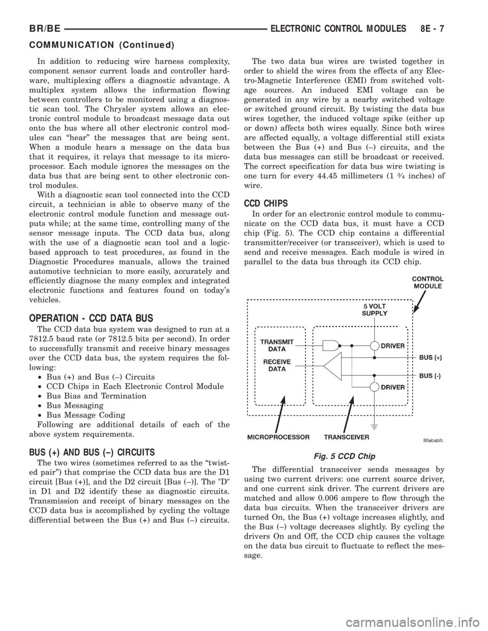
chip (Fig. 5). The CCD chip contains a differential
transmitter/receiver (or transceiver), which is used to
send and receive messages. Each module is wired in
parallel to the data bus through its CCD chip.
The differential transceiver sends messages by
using two current drivers: one current source driver,
and one current sink driver. The current drivers are
matched and allow 0.006 ampere to flow through the
data bus circuits. When the transceiver drivers are
turned On, the Bus (+) voltage increases slightly, and
the Bus (±) voltage decreases slightly. By cycling the
drivers On and Off, the CCD chip causes the voltage
on the data bus circuit to fluctuate to reflect the mes-
sage.
Fig. 5 CCD Chip
BR/BEELECTRONIC CONTROL MODULES 8E - 7
COMMUNICATION (Continued)
Page 459 of 2889
Once a message is broadcast over the CCD data
bus, all electronic control modules on the data bus
have the ability to receive it through their CCD chip.
Reception of CCD messages is also carried out by the
transceiver in the CCD chip. The transceiver moni-
tors the voltage on the data bus for any fluctuations.
When data bus voltage fluctuations are detected,
they are interpreted by the transceiver as binary
messages and sent to the electronic control module's
microprocessor.
BUS BIAS AND TERMINATION
The voltage network used by the CCD data bus to
transmit messages requires both bias and termina-
tion. At least one electronic control module on the
data bus must provide a voltage source for the CCD
data bus network known as bus bias, and there must
be at least one bus termination point for the data bus
circuit to be complete. However, while bias and ter-
mination are both required for data bus operation,
they both do not have to be within the same elec-
tronic control module. The CCD data bus is biased to
approximately 2.5 volts. With each of the electronic
control modules wired in parallel to the data bus, all
modules utilize the same bus bias. Therefore, based
upon vehicle options, the data bus can accommodate
two or twenty electronic control modules without
affecting bus voltage.
The power supplied to the data bus is known as
bus biasing. Bus bias is provided through a series cir-
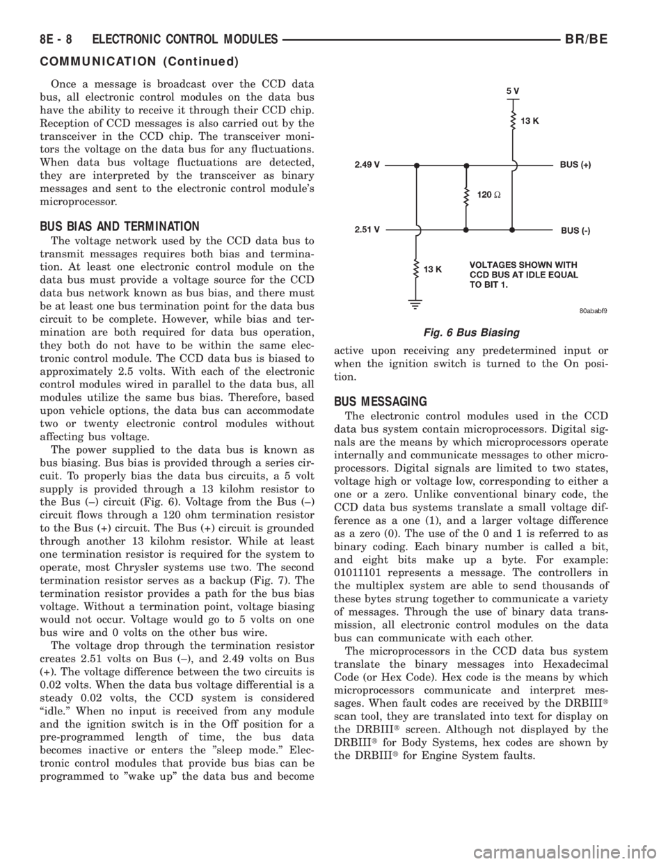
cuit. To properly bias the data bus circuits, a 5 volt
supply is provided through a 13 kilohm resistor to
the Bus (±) circuit (Fig. 6). Voltage from the Bus (±)
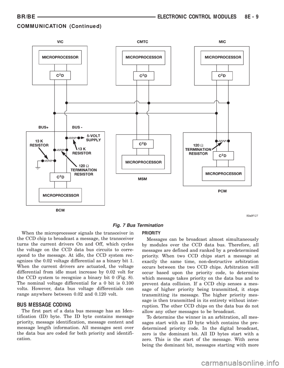
circuit flows through a 120 ohm termination resistor
to the Bus (+) circuit. The Bus (+) circuit is grounded
through another 13 kilohm resistor. While at least
one termination resistor is required for the system to
operate, most Chrysler systems use two. The second
termination resistor serves as a backup (Fig. 7). The
termination resistor provides a path for the bus bias
voltage. Without a termination point, voltage biasing
would not occur. Voltage would go to 5 volts on one
bus wire and 0 volts on the other bus wire.
The voltage drop through the termination resistor
creates 2.51 volts on Bus (±), and 2.49 volts on Bus
(+). The voltage difference between the two circuits is
0.02 volts. When the data bus voltage differential is a
steady 0.02 volts, the CCD system is considered
ªidle.º When no input is received from any module
and the ignition switch is in the Off position for a
pre-programmed length of time, the bus data
becomes inactive or enters the ºsleep mode.º Elec-
tronic control modules that provide bus bias can be
programmed to ºwake upº the data bus and becomeactive upon receiving any predetermined input or
when the ignition switch is turned to the On posi-
tion.
BUS MESSAGING
The electronic control modules used in the CCD
data bus system contain microprocessors. Digital sig-
nals are the means by which microprocessors operate
internally and communicate messages to other micro-
processors. Digital signals are limited to two states,
voltage high or voltage low, corresponding to either a
one or a zero. Unlike conventional binary code, the
CCD data bus systems translate a small voltage dif-
ference as a one (1), and a larger voltage difference
as a zero (0). The use of the 0 and 1 is referred to as
binary coding. Each binary number is called a bit,
and eight bits make up a byte. For example:
01011101 represents a message. The controllers in
the multiplex system are able to send thousands of
these bytes strung together to communicate a variety
of messages. Through the use of binary data trans-
mission, all electronic control modules on the data
bus can communicate with each other.
The microprocessors in the CCD data bus system
translate the binary messages into Hexadecimal
Code (or Hex Code). Hex code is the means by which
microprocessors communicate and interpret mes-
sages. When fault codes are received by the DRBIIIt
scan tool, they are translated into text for display on
the DRBIIItscreen. Although not displayed by the
DRBIIItfor Body Systems, hex codes are shown by
the DRBIIItfor Engine System faults.
Fig. 6 Bus Biasing
8E - 8 ELECTRONIC CONTROL MODULESBR/BE
COMMUNICATION (Continued)
Page 460 of 2889
When the microprocessor signals the transceiver in
the CCD chip to broadcast a message, the transceiver
turns the current drivers On and Off, which cycles
the voltage on the CCD data bus circuits to corre-
spond to the message. At idle, the CCD system rec-
ognizes the 0.02 voltage differential as a binary bit 1.
When the current drivers are actuated, the voltage
differential from idle must increase by 0.02 volt for
the CCD system to recognize a binary bit 0 (Fig. 8).
The nominal voltage differential for a 0 bit is 0.100
volts. However, data bus voltage differentials can
range anywhere between 0.02 and 0.120 volt.
BUS MESSAGE CODING
The first part of a data bus message has an Iden-
tification (ID) byte. The ID byte contains message
priority, message identification, message content and
message length information. All messages sent over
the data bus are coded for both priority and identifi-
cation.PRIORITY
Messages can be broadcast almost simultaneously
by modules over the CCD data bus. Therefore, all
messages are defined and ranked by a predetermined
priority. When two CCD chips start a message at
exactly the same time, non-destructive arbitration
occurs between the two CCD chips. Arbitration will
occur based upon the priority code, to determine
which message takes priority on the data bus and to
prevent data collision. If a CCD chip senses a mes-
sage of higher priority being transmitted, it stops
transmitting its message. The higher priority mes-
sage is then transmitted in its entirety without inter-
ruption. The other CCD chips on the data bus do not
allow any other messages to be broadcast.
To determine the winner in an arbitration, all mes-
sages start with an ID byte which contains the pre-
determined priority code. In the digital broadcast,
zero is the dominant bit. All ID bytes start with a
zero. This is the start of the message. With zeros
being the dominant bit, messages starting with more
Fig. 7 Bus Termination
BR/BEELECTRONIC CONTROL MODULES 8E - 9
COMMUNICATION (Continued)