DODGE RAM 2001 Service Repair Manual
Manufacturer: DODGE, Model Year: 2001, Model line: RAM, Model: DODGE RAM 2001Pages: 2889, PDF Size: 68.07 MB
Page 441 of 2889
PREMIUM
The Infinity speakers used in the premium speaker
system are driven by dual amplifiers that are inte-
gral to each of the front door speakers. One of these
dual amplifiers drives the front door speaker and the
A-pillar mounted tweeter for that side of the vehicle,
while the other amplifier drives the rear speaker for
that side of the vehicle. For complete circuit dia-
grams, to refer to the appropriate wiring information.
The wiring information includes wiring diagrams,
proper wire and connector repair procedures, details
of wire harness routing and retention, connector pin-
out information and location views for the various
wire harness connectors, splices and grounds.
DIAGNOSIS AND TESTING - SPEAKER
For complete circuit diagrams, refer to the appro-
priate wiring information. The wiring information
includes wiring diagrams, proper wire and connector
repair procedures, details of wire harness routing
and retention, connector pin-out information and
location views for the various wire harness connec-
tors, splices and grounds.
WARNING: ON VEHICLES EQUIPPED WITH AIR-
BAGS, REFER TO ELECTRICAL, RESTRAINTS
BEFORE ATTEMPTING ANY STEERING WHEEL,
STEERING COLUMN, OR INSTRUMENT PANEL
COMPONENT DIAGNOSIS OR SERVICE. FAILURE
TO TAKE THE PROPER PRECAUTIONS COULD
RESULT IN ACCIDENTAL AIRBAG DEPLOYMENT
AND POSSIBLE PERSONAL INJURY.
CAUTION: The speaker output of the radio receiver
is a ªfloating groundº system. Do not allow any
speaker lead to short to ground, as damage to the
radio receiver may result.
(1) Turn the ignition switch to the On position.
Turn the radio receiver on. Adjust the balance and
fader controls to check the performance of each indi-
vidual speaker. Note the speaker locations that are
not performing correctly. If only an Infinity A-pillar
or an Infinity rear speaker is inoperative, go to Step
8. If any other speaker is inoperative, go to Step 2.
NOTE: If the vehicle is equipped with the Infinity
premium speaker package and all of the speakers
are inoperative, refer to Filter, Choke, and Speaker
Relay in the Diagnosis and Testing section of this
group.
(2) Turn the radio receiver off. Turn the ignition
switch to the Off position. Disconnect and isolate the
battery negative cable. Remove the radio receiver
from the instrument panel. Check both the feed (+)circuit and return (±) circuit cavities for the inopera-
tive speaker location(s) in the radio receiver wire
harness connectors for continuity to ground. In each
case, there should be no continuity. If OK, go to Step
3. If not OK, repair the shorted speaker feed (+)
and/or return (±) circuit(s) to the speaker as required.
(3) If the inoperative speaker is an Infinity-ampli-
fied speaker, go to Step 5. If the vehicle is equipped
with the standard speaker system, check the resis-
tance between the speaker feed (+) circuit and return
(±) circuit cavities of the radio receiver wire harness
connectors for the inoperative speaker location(s).
The meter should read between 2.5 and 4 ohms
(speaker resistance). If OK, go to Step 4. If not OK,
go to Step 5.
(4) Install a known good radio receiver. Connect
the battery negative cable. Turn the ignition switch
to the On position. Turn on the radio receiver and
test the speaker operation. If OK, replace the faulty
radio receiver. If not OK, turn the radio receiver off,
turn the ignition switch to the Off position, discon-
nect and isolate the battery negative cable, remove
the test radio receiver, and go to Step 5.
(5) Disconnect the wire harness connector at the
inoperative standard speaker system speaker or at
the Infinity-amplified front door-mounted speaker.
Check for continuity between the speaker feed (+) cir-
cuit cavities of the radio receiver wire harness con-
nector and the speaker wire harness connector for
the inoperative speaker location. Repeat the check
between the speaker return (±) circuit cavities of the
radio receiver wire harness connector and the
speaker wire harness connector for the inoperative
speaker location. In each case, there should be conti-
nuity. If OK with an Infinity-amplified front door-
mounted speaker, go to Step 6. If OK with the
standard speaker system, replace the faulty speaker.
If not OK, repair the open speaker feed (+) and/or
return (±) circuit(s) as required.
(6) Check for continuity between the ground cir-
cuit cavity in the body half of the wire harness con-
nector for the Infinity-amplified front door-mounted
speaker on the same side of the vehicle as the inop-
erative speaker and a good ground. There should be
continuity. If OK, go to Step 7. If not OK, repair the
open ground circuit to ground as required.
(7) Install the radio receiver. Connect the battery
negative cable. Turn the ignition switch to the On
position. Turn the radio receiver on. Check for bat-
tery voltage at the radio choke output circuit cavity
of the wire harness connector for the Infinity-ampli-
fied front door-mounted speaker on the same side of
the vehicle as the inoperative speaker. If OK, go to
Step 8. If not OK, repair the open radio choke output
circuit to the filter, choke, and speaker relay as
required.
8A - 18 AUDIOBR/BE
SPEAKER (Continued)
Page 442 of 2889
(8) Turn the radio receiver off. Turn the ignition
switch to the Off position. Disconnect and isolate the
battery negative cable. Disconnect the wire harness
connector for the Infinity-amplified front door-
mounted speaker on the same side of the vehicle as
the inoperative speaker. Check both the amplified
feed (+) circuit and amplified return (±) circuit cavi-
ties for the inoperative speaker location in the body
half of the front door speaker wire harness connector
for continuity to ground. In each case, there should
be no continuity. If OK, go to Step 9. If not OK,
repair the shorted amplified feed (+) and/or amplified
return (±) circuit(s) as required.
(9) Disconnect the wire harness connector at the
inoperative speaker. Check for continuity between
the amplified feed (+) circuit cavities in the body half
of the wire harness connector for the Infinity-ampli-
fied front door-mounted speaker on the same side of
the vehicle as the inoperative speaker and the inop-
erative speaker wire harness connector. Repeat the
check between the amplified return (±) circuit cavi-
ties in the body half of the wire harness connector for
the Infinity-amplified front door-mounted speaker on
the same side of the vehicle as the inoperative
speaker and the inoperative speaker wire harness
connector. In each case, there should be continuity. If
OK, go to Step 10. If not OK, repair the open ampli-
fied feed (+) and/or amplified return (±) circuit(s) as
required.
(10) Check the resistance between the amplified
feed (+) circuit and amplified return (±) circuit cavi-
ties for the inoperative speaker in the body half of
the wire harness connector for the Infinity-amplified
front door-mounted speaker on the same side of the
vehicle as the inoperative speaker. The meter should
read between 2.5 and 4 ohms (speaker resistance). If
OK, replace the faulty front door-mounted Infinity
speaker and amplifier unit. If not OK, replace the
faulty A-pillar or rear-mounted Infinity speaker.
A-PILLAR TWEETER SPEAKER
REMOVAL
The A-pillar-mounted tweeters are used only with
the optional Infinity premium speaker package.
(1) Disconnect and isolate the battery negative
cable.
(2) If the vehicle is so equipped, remove the grab
handle from the A-pillar. Refer to Body, Interior for
the procedures.
(3) Disengage the trim from the A-pillar. Refer to
Body, Interior for the procedures.
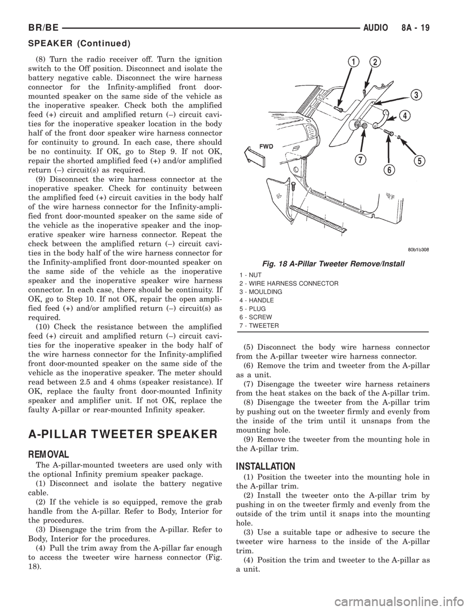
(4) Pull the trim away from the A-pillar far enough
to access the tweeter wire harness connector (Fig.
18).(5) Disconnect the body wire harness connector
from the A-pillar tweeter wire harness connector.
(6) Remove the trim and tweeter from the A-pillar
as a unit.
(7) Disengage the tweeter wire harness retainers
from the heat stakes on the back of the A-pillar trim.
(8) Disengage the tweeter from the A-pillar trim
by pushing out on the tweeter firmly and evenly from
the inside of the trim until it unsnaps from the
mounting hole.
(9) Remove the tweeter from the mounting hole in
the A-pillar trim.INSTALLATION
(1) Position the tweeter into the mounting hole in
the A-pillar trim.
(2) Install the tweeter onto the A-pillar trim by
pushing in on the tweeter firmly and evenly from the
outside of the trim until it snaps into the mounting
hole.
(3) Use a suitable tape or adhesive to secure the
tweeter wire harness to the inside of the A-pillar
trim.
(4) Position the trim and tweeter to the A-pillar as
a unit.
Fig. 18 A-Pillar Tweeter Remove/Install
1 - NUT
2 - WIRE HARNESS CONNECTOR
3 - MOULDING
4 - HANDLE
5 - PLUG
6 - SCREW
7 - TWEETER
BR/BEAUDIO 8A - 19
SPEAKER (Continued)
Page 443 of 2889
(5) Reconnect the body wire harness connector to
the A-pillar tweeter wire harness connector.
(6) Engage the trim onto the A-pillar. Refer to
Body, Interior for the procedures.
(7) If the vehicle is so equipped, install the grab
handle onto the A-pillar. Refer to Body, Interior for
the procedures.
(8) Reconnect the battery negative cable.
FRONT DOOR SPEAKER
REMOVAL
(1) Disconnect and isolate the battery negative
cable.
(2) Remove the trim panel from the front door.
Refer to Body, Door Front for the procedures.
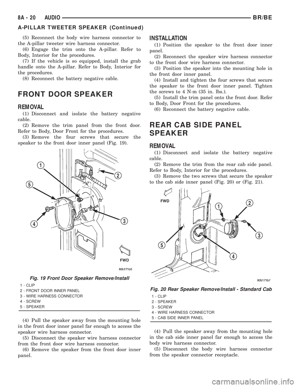
(3) Remove the four screws that secure the
speaker to the front door inner panel (Fig. 19).
(4) Pull the speaker away from the mounting hole
in the front door inner panel far enough to access the
speaker wire harness connector.
(5) Disconnect the speaker wire harness connector
from the front door wire harness connector.
(6) Remove the speaker from the front door inner
panel.
INSTALLATION
(1) Position the speaker to the front door inner
panel.
(2) Reconnect the speaker wire harness connector
to the front door wire harness connector.
(3) Position the speaker into the mounting hole in
the front door inner panel.
(4) Install and tighten the four screws that secure
the speaker to the front door inner panel. Tighten
the screws to 4 N´m (35 in. lbs.).
(5) Install the trim panel onto the front door. Refer
to Body, Door Front for the procedures.
(6) Reconnect the battery negative cable.
REAR CAB SIDE PANEL
SPEAKER
REMOVAL
(1) Disconnect and isolate the battery negative
cable.
(2) Remove the trim from the rear cab side panel.
Refer to Body, Interior for the procedures.
(3) Remove the two screws that secure the speaker
to the cab side inner panel (Fig. 20) or (Fig. 21).
(4) Pull the speaker away from the mounting hole
in the cab side inner panel far enough to access the
body wire harness connector.
(5) Disconnect the body wire harness connector
from the speaker connector receptacle.
Fig. 19 Front Door Speaker Remove/Install
1 - CLIP
2 - FRONT DOOR INNER PANEL
3 - WIRE HARNESS CONNECTOR
4 - SCREW
5 - SPEAKERFig. 20 Rear Speaker Remove/Install - Standard Cab
1 - CLIP
2 - SPEAKER
3 - SCREW
4 - WIRE HARNESS CONNECTOR
5 - CAB SIDE INNER PANEL
8A - 20 AUDIOBR/BE
A-PILLAR TWEETER SPEAKER (Continued)
Page 444 of 2889
(6) Remove the speaker from the cab side inner
panel.
INSTALLATION
(1) Position the speaker to the cab side inner
panel.
(2) Reconnect the body wire harness connector to
the speaker connector receptacle.
(3) Position the speaker into the mounting hole in
the cab side inner panel.
(4) Install and tighten the two screws that secure
the speaker to the cab side inner panel. Tighten the
screws to 4 N´m (35 in. lbs.).
(5) Install the trim onto the rear cab side panel.
Refer to Body, Interior for the procedures.
(6) Reconnect the battery negative cable.
REAR DOOR SPEAKER
REMOVAL
(1) Disconnect and isolate the battery negative
cable.
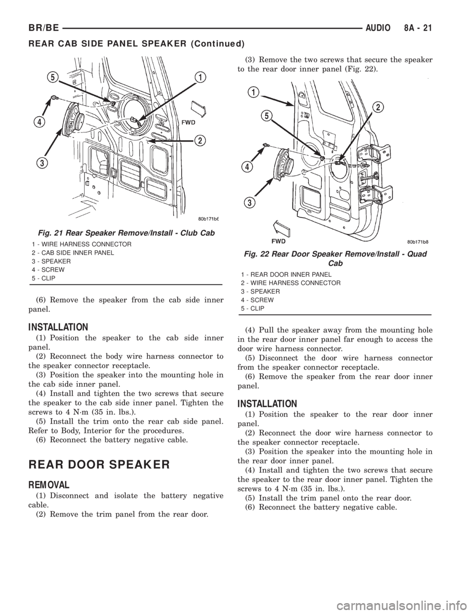
(2) Remove the trim panel from the rear door.(3) Remove the two screws that secure the speaker
to the rear door inner panel (Fig. 22).
(4) Pull the speaker away from the mounting hole
in the rear door inner panel far enough to access the
door wire harness connector.
(5) Disconnect the door wire harness connector
from the speaker connector receptacle.
(6) Remove the speaker from the rear door inner
panel.
INSTALLATION
(1) Position the speaker to the rear door inner
panel.
(2) Reconnect the door wire harness connector to
the speaker connector receptacle.
(3) Position the speaker into the mounting hole in
the rear door inner panel.
(4) Install and tighten the two screws that secure
the speaker to the rear door inner panel. Tighten the
screws to 4 N´m (35 in. lbs.).
(5) Install the trim panel onto the rear door.
(6) Reconnect the battery negative cable.
Fig. 21 Rear Speaker Remove/Install - Club Cab
1 - WIRE HARNESS CONNECTOR
2 - CAB SIDE INNER PANEL
3 - SPEAKER
4 - SCREW
5 - CLIP
Fig. 22 Rear Door Speaker Remove/Install - Quad
Cab
1 - REAR DOOR INNER PANEL
2 - WIRE HARNESS CONNECTOR
3 - SPEAKER
4 - SCREW
5 - CLIP
BR/BEAUDIO 8A - 21
REAR CAB SIDE PANEL SPEAKER (Continued)
Page 445 of 2889

Page 446 of 2889
CHIME/BUZZER
TABLE OF CONTENTS
page page
CHIME WARNING SYSTEM
DESCRIPTION............................1
OPERATION.............................1DIAGNOSIS AND TESTING..................2
CHIME WARNING SYSTEM................2
CHIME WARNING SYSTEM
DESCRIPTION
A chime warning system is standard factory-in-
stalled equipment on this model. The chime warning
system uses a single chime tone generator that is
integral to the Central Timer Module (CTM) to pro-
vide an audible indication of various vehicle condi-
tions that may require the attention of the vehicle
operator. The chime warning system includes the fol-
lowing major components, which are described in fur-
ther detail elsewhere in this service manual:
²Central Timer Module- The Central Timer
Module (CTM) is located under the driver side end of
the instrument panel, inboard of the instrument
panel steering column opening. The CTM contains an
integral chime tone generator to provide all of the
proper chime warning system features based upon
the monitored inputs.
²Door Ajar Switch- A door ajar switch is inte-
gral to the driver side front door latch. This switch
provides an input to the chime warning system indi-
cating whether the driver side front door is open or
closed.
²Headlamp Switch- The headlamp switch is
located on the instrument panel outboard of the
steering column. The headlamp switch provides an
input to the chime warning system indicating when
the exterior lamps are turned On or Off.
²Ignition Switch- A key-in ignition switch is
integral to the ignition switch. The key-in ignition
switch provides an input to the chime warning sys-
tem indicating whether a key is present in the igni-
tion lock cylinder.
²Seat Belt Switch- A seat belt switch is inte-
gral to the driver side front seat belt retractor unit.
The seat belt switch provides an input to the chime
warning system indicating whether the driver side
front seat belt is fastened.
Hard wired circuitry connects many of the chime
warning system components to each other through
the electrical system of the vehicle. These hard wired
circuits are integral to several wire harnesses, which
are routed throughout the vehicle and retained bymany different methods. These circuits may be con-
nected to each other, to the vehicle electrical system
and to the chime warning system components
through the use of a combination of soldered splices,
splice block connectors, and many different types of
wire harness terminal connectors and insulators.
Refer to the appropriate wiring information. The wir-
ing information includes wiring diagrams, proper
wire and connector repair procedures, further details
on wire harness routing and retention, as well as
pin-out and location views for the various wire har-
ness connectors, splices and grounds.
The CTM chime warning system circuitry and the
integral chime tone generator cannot be adjusted or
repaired. If the CTM or the chime tone generator are
damaged or faulty, the CTM unit must be replaced.
OPERATION
The chime warning system is designed to provide an
audible output as an indication of various conditions
that may require the attention or awareness of the
vehicle operator. The chime warning system compo-
nents operate on battery current received through a
fused B(+) fuse in the Junction Block (JB) on a non-
switched fused B(+) circuit so that the system may
operate regardless of the ignition switch position.
The chime warning system provides an audible
indication to the vehicle operator under the following
conditions:
²Fasten Seat Belt Warning- The Central
Timer Module (CTM) chime tone generator will gen-
erate repetitive chime tones at a slow rate to
announce that a hard wired input from the seat belt
switch to the Electro-Mechanical Instrument Cluster
(EMIC) indicates that the driver side front seat belt
is not fastened with the ignition switch in the On
position. Unless the driver side front seat belt is fas-
tened, the chimes will continue to sound for a dura-
tion of about seven seconds each time the ignition
switch is turned to the On position or until the driver
side front seat belt is fastened, whichever occurs
first. This chime tone is based upon a hard wired
chime request input to the CTM from the EMIC, but
is not related to the operation of the EMIC ªSeatbeltº
indicator.
BR/BECHIME/BUZZER 8B - 1
Page 447 of 2889
²Head/Park Lights-On Warning- The CTM
chime tone generator will generate repetitive chime
tones at a fast rate to announce that hard wired
inputs from the driver door ajar switch, headlamp
switch, and ignition switch indicate that the exterior
lamps are turned On with the driver side front door
opened and the ignition switch in the Off position.
The chimes will continue to sound until the exterior
lamps are turned Off, the driver side front door is
closed, or the ignition switch is turned to the On
position, whichever occurs first.
²Key-In-Ignition Warning- The BCM chime
tone generator will generate repetitive chime tones at
a fast rate to announce that hard wired inputs from
the driver door ajar switch, headlamp switch, and
ignition switch indicate that the key is in the ignition
lock cylinder with the driver side front door opened
and the ignition switch in the Off position. The
chimes will continue to sound until the key is
removed from the ignition lock cylinder, the driver
side front door is closed, or the ignition switch is
turned to the On position, whichever occurs first.
²Warning Chime Support- The CTM chime
tone generator will generate repetitive chime tones at
a slow rate to announce that a hard wired chime
request input has been received from the EMIC.
These chime tones provide an audible alert to the
vehicle operator that supplements certain visual indi-
cations displayed by the EMIC. Supplemented indica-
tions include the following:
²The ªAirbagº indicator is illuminated. The
chimes will continue to sound for a duration of about
four seconds each time the indicator is illuminated or
until the ignition switch is turned to the Off position,
whichever occurs first.
²The ªCheck Gagesº indicator is illuminated. The
chimes will continue to sound for a duration of about
two seconds each time the indicator is illuminated or
until the ignition switch is turned to the Off position,
whichever occurs first.
²The ªLow Fuelº indicator is illuminated. The
chimes will continue to sound for a duration of about
two seconds each time the indicator is illuminated or
until the ignition switch is turned to the Off position,
whichever occurs first.
²The ªLow Washº indicator is illuminated. The
chimes will continue to sound for a duration of about
two seconds each time the indicator is illuminated or
until the ignition switch is turned to the Off position,
whichever occurs first.
²The ªTrans Tempº indicator is illuminated (auto-
matic transmission only). The chimes will continue to
sound for a duration of about two seconds each time
the indicator is illuminated or until the ignition
switch is turned to the Off position, whichever occurs
first.²The vehicle is over a programmed speed value
(Middle East Gulf Coast Country (GCC) only). The
CTM chime tone generator will generate repetitive
chime tones at a slow rate to announce that the vehi-
cle speed exceeds a programmed value. The chimes
will continue to sound until the vehicle speed is
below the programmed value.
²The ªWater-In-Fuelº indicator is illuminated
(diesel engine only). The chimes will continue to
sound for a duration of about two seconds each time
the indicator is illuminated or until the ignition
switch is turned to the Off position, whichever occurs
first.
The CTM provides chime service for all available
features in the chime warning system. The CTM
relies upon hard wired inputs from the driver door
ajar switch, the EMIC, the headlamp switch, and the
key-in ignition switch (ignition switch) to provide
chime service for all of the chime warning system
features. Upon receiving the proper inputs, the CTM
activates the integral chime tone generator to pro-
vide the audible chime tone to the vehicle operator.
The chime tone generator in the CTM is capable of
producing repeated chime tones at two different
rates, slow or fast. The slow chime rate is about fifty
chime tones per minute, while the fast chime rate is
about 180 chime tones per minute. The internal pro-
gramming of the CTM and the EMIC determines the
priority of each chime tone request input that is
received, as well as the rate and duration of each
chime tone that is to be generated.
The hard wired chime warning system inputs to
the CTM and the EMIC, as well as other hard wired
circuits for this system may be diagnosed and tested
using conventional diagnostic tools and procedures.
See the owner's manual in the vehicle glove box for
more information on the features provided by the
chime warning system.
DIAGNOSIS AND TESTING - CHIME WARNING
SYSTEM
Refer to the appropriate wiring information. The
wiring information includes wiring diagrams, proper
wire and connector repair procedures, further details
on wire harness routing and retention, as well as
pin-out and location views for the various wire har-
ness connectors, splices and grounds. The hard wired
chime warning system inputs to the Central Timer
Module (CTM) and the Electro-Mechanical Instru-
ment Cluster (EMIC), as well as other hard wired
circuits for this system may be diagnosed and tested
using conventional diagnostic tools and procedures.
8B - 2 CHIME/BUZZERBR/BE
CHIME WARNING SYSTEM (Continued)
Page 448 of 2889
WARNING: ON VEHICLES EQUIPPED WITH AIR-
BAGS, DISABLE THE AIRBAG SYSTEM BEFORE
ATTEMPTING ANY STEERING WHEEL, STEERING
COLUMN, OR INSTRUMENT PANEL COMPONENT
DIAGNOSIS OR SERVICE. DISCONNECT AND ISO-
LATE THE BATTERY NEGATIVE (GROUND) CABLE,
THEN WAIT TWO MINUTES FOR THE AIRBAG SYS-TEM CAPACITOR TO DISCHARGE BEFORE PER-
FORMING FURTHER DIAGNOSIS OR SERVICE. THIS
IS THE ONLY SURE WAY TO DISABLE THE AIRBAG
SYSTEM. FAILURE TO TAKE THE PROPER PRE-
CAUTIONS COULD RESULT IN ACCIDENTAL AIR-
BAG DEPLOYMENT AND POSSIBLE PERSONAL
INJURY.
CHIME WARNING SYSTEM DIAGNOSIS
CONDITION POSSIBLE CAUSES CORRECTION
SEAT BELT WARNING
CHIME WITH SEAT BELT
BUCKLED1. Seat belt switch sense
circuit shorted.1. Disconnect the body wire harness connector
for the seat belt switch and the instrument panel
wire harness connector (Connector C2) for the
EMIC. Check for continuity between the seat belt
switch sense circuit cavity and a good ground.
There should be no continuity. Repair the seat
belt switch sense circuit, if required.
2. Faulty seat belt switch. 2. Check for continuity between the ground circuit
cavity and the seat belt switch sense circuit cavity
of the seat belt switch connector receptacle.
There should be no continuity with the seat belt
buckled. Replace the faulty seat belt, if required.
NO SEAT BELT WARNING
CHIME WITH SEAT BELT
UNBUCKLED, BUT OTHER
CHIME FEATURES OK1. Seat belt switch ground
circuit open.1. Disconnect the body wire harness connector
for the seat belt switch. Check for continuity
between the ground circuit cavity of the connector
for the seat belt switch and a good ground. There
should be continuity. If not OK, repair the open
ground circuit to ground as required.
2. Seat belt switch sense
circuit open.2. With the body wire harness connector for the
seat belt switch and the instrument panel wire
harness connector (Connector C2) for the EMIC
disconnected, there should be continuity between
the seat belt switch sense circuit cavities of the
two connectors. Repair the seat belt switch sense
circuit, if required.
3. Faulty seat belt switch. 3. Check for continuity between the ground circuit
cavity and the seat belt switch sense circuit cavity
of the seat belt switch connector receptacle.
There should be continuity with the seat belt
unbuckled. Replace the faulty seat belt, if
required.
BR/BECHIME/BUZZER 8B - 3
CHIME WARNING SYSTEM (Continued)
Page 449 of 2889
CHIME WARNING SYSTEM DIAGNOSIS
CONDITION POSSIBLE CAUSES CORRECTION
NO KEY-IN IGNITION
WARNING CHIME, BUT
OTHER CHIME FEATURES
OK1. Driver door ajar switch
sense circuit open.1. Check for continuity between the driver door
ajar switch sense circuit cavities of the connector
for the driver side front door ajar switch and the
instrument panel wire harness connector
(Connector C2) for the ignition switch. Repair the
driver door ajar switch sense circuit, if required.
2. Key-in ignition switch
sense circuit open.2. Check for continuity between the key-in ignition
switch sense circuit cavities of the instrument
panel wire harness connector (Connector C2) for
the ignition switch and the instrument panel wire
harness connector for the CTM. Repair the key-in
ignition switch sense circuit, if required.
3. Faulty ignition switch. 3. Check for continuity between the two terminals
in the ignition switch C2 connector receptacle.
There should be continuity with a key in the
ignition lock cylinder. Replace the faulty ignition
switch, if required.
NO HEADLAMPS-ON
WARNING CHIME, BUT
OTHER CHIME FEATURES
OK1. Driver door ajar switch
sense circuit open.1. Check for continuity between the driver door
ajar switch sense circuit cavities of the connector
for the driver side front door ajar switch and the
instrument panel wire harness connector
(Connector C1) for the headlamp switch. Repair
the driver door ajar switch sense circuit, if
required.
2. Key-in ignition switch
sense circuit open.2. Check for continuity between the key-in ignition
switch sense circuit cavities of the instrument
panel wire harness connector (Connector C1) for
the headlamp switch and the instrument panel
wire harness connector for the CTM. Repair the
key-in ignition switch sense circuit, if required.
3. Faulty headlamp switch. 3. Check for continuity between the driver door
ajar switch sense terminal and the key-in ignition
switch sense terminal in the headlamp switch C1
connector receptacle. There should be continuity
with the headlamp switch in the On position.
Replace the faulty headlamp switch, if required.
CONTINUOUS CHIME WITH
HEADLAMP SWITCH IN OFF
POSITION AND KEY
REMOVED FROM IGNITION
LOCK CYLINDER1. Key-in ignition switch
sense circuit shorted.1. With the instrument panel wire harness
connector (Connector C1) for the headlamp
switch, the instrument panel wire harness
connector (Connector C2) for the ignition switch,
and the instrument panel wire harness connector
for the CTM all disconnected, there should be no
continuity between the key-in ignition switch
sense circuit and a good ground. Repair the
key-in ignition switch sense circuit, if required.
2. Faulty CTM. 2. Replace the faulty CTM, if required.
8B - 4 CHIME/BUZZERBR/BE
CHIME WARNING SYSTEM (Continued)
Page 450 of 2889
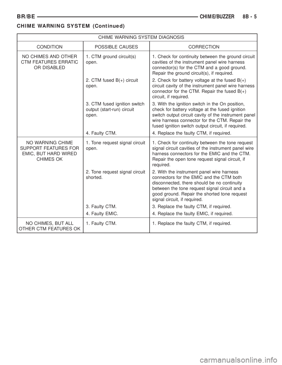
CHIME WARNING SYSTEM DIAGNOSIS
CONDITION POSSIBLE CAUSES CORRECTION
NO CHIMES AND OTHER
CTM FEATURES ERRATIC
OR DISABLED1. CTM ground circuit(s)
open.1. Check for continuity between the ground circuit
cavities of the instrument panel wire harness
connector(s) for the CTM and a good ground.
Repair the ground circuit(s), if required.
2. CTM fused B(+) circuit
open.2. Check for battery voltage at the fused B(+)
circuit cavity of the instrument panel wire harness
connector for the CTM. Repair the fused B(+)
circuit, if required.
3. CTM fused ignition switch
output (start-run) circuit
open.3. With the ignition switch in the On position,
check for battery voltage at the fused ignition
switch output circuit cavity of the instrument panel
wire harness connector for the CTM. Repair the
fused ignition switch output circuit, if required.
4. Faulty CTM. 4. Replace the faulty CTM, if required.
NO WARNING CHIME
SUPPORT FEATURES FOR
EMIC, BUT HARD WIRED
CHIMES OK1. Tone request signal circuit
open.1. Check for continuity between the tone request
signal circuit cavities of the instrument panel wire
harness connectors for the EMIC and the CTM.
Repair the open tone request signal circuit, if
required.
2. Tone request signal circuit
shorted.2. With the instrument panel wire harness
connectors for the EMIC and the CTM both
disconnected, there should be no continuity
between the tone request signal circuit and a
good ground. Repair the shorted tone request
signal circuit, if required.
3. Faulty CTM. 3. Replace the faulty CTM, if required.
4. Faulty EMIC. 4. Replace the faulty EMIC, if required.
NO CHIMES, BUT ALL
OTHER CTM FEATURES OK1. Faulty CTM. 1. Replace the faulty CTM, if required.
BR/BECHIME/BUZZER 8B - 5
CHIME WARNING SYSTEM (Continued)