DODGE RAM 2002 Service Repair Manual
Manufacturer: DODGE, Model Year: 2002, Model line: RAM, Model: DODGE RAM 2002Pages: 2255, PDF Size: 62.07 MB
Page 1401 of 2255
INSTALLATION
The fuel injectors are located in the top of the cyl-
inder head between the intake/exhaust valves (Fig.
18).
(1) Inspect fuel injector.
(a) If necessary, perform pressure test of injector.
Refer to Fuel Injector Testing.
(b) Look for burrs on injector inlet.(c) Check nozzle holes for hole erosion or plug-
ging.
(d) Inspect end of nozzle for burrs or rough
machine marks.
(e) Look for cracks at nozzle end.
(f) Check nozzle color for signs of overheating.
Overheating will cause nozzle to turn a dark yel-
low/tan or blue (depending on overheating temper-
ature).
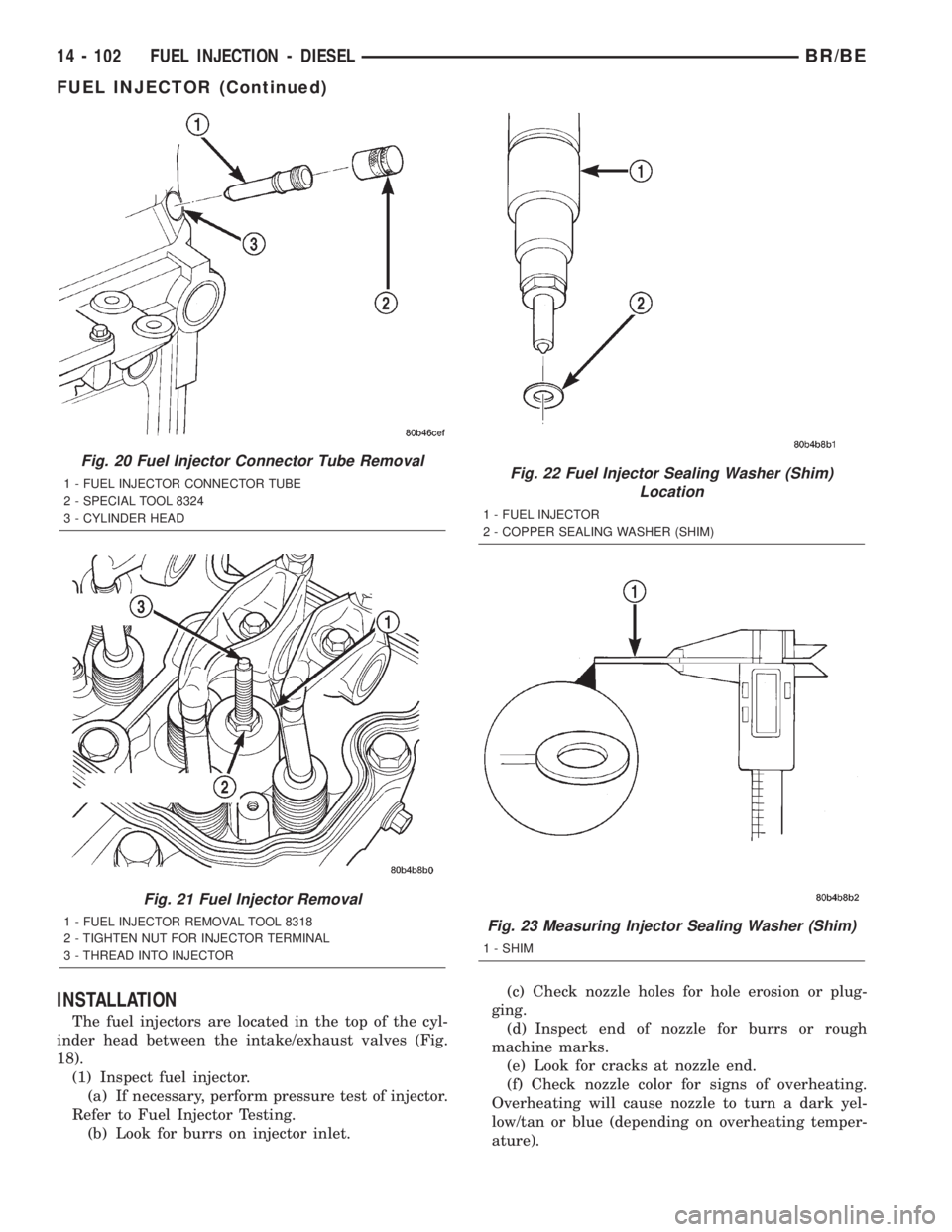
Fig. 20 Fuel Injector Connector Tube Removal
1 - FUEL INJECTOR CONNECTOR TUBE
2 - SPECIAL TOOL 8324
3 - CYLINDER HEAD
Fig. 21 Fuel Injector Removal
1 - FUEL INJECTOR REMOVAL TOOL 8318
2 - TIGHTEN NUT FOR INJECTOR TERMINAL
3 - THREAD INTO INJECTOR
Fig. 22 Fuel Injector Sealing Washer (Shim)
Location
1 - FUEL INJECTOR
2 - COPPER SEALING WASHER (SHIM)
Fig. 23 Measuring Injector Sealing Washer (Shim)
1 - SHIM
14 - 102 FUEL INJECTION - DIESELBR/BE
FUEL INJECTOR (Continued)
Page 1402 of 2255
(g) If any of these conditions occur, replace injec-
tor.
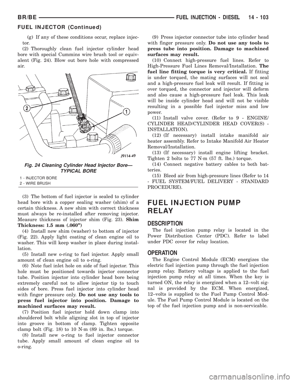
(2) Thoroughly clean fuel injector cylinder head
bore with special Cummins wire brush tool or equiv-
alent (Fig. 24). Blow out bore hole with compressed
air.
(3) The bottom of fuel injector is sealed to cylinder
head bore with a copper sealing washer (shim) of a
certain thickness. A new shim with correct thickness
must always be re-installed after removing injector.
Measure thickness of injector shim (Fig. 23).Shim
Thickness: 1.5 mm (.060º)
(4) Install new shim (washer) to bottom of injector
(Fig. 22). Apply light coating of clean engine oil to
washer. This will keep washer in place during instal-
lation.
(5) Install new o-ring to fuel injector. Apply small
amount of clean engine oil to o-ring.
(6) Note fuel inlet hole on side of fuel injector. This
hole must be positioned towards injector connector
tube. Position injector into cylinder head bore being
extremely careful not to allow injector tip to touch
sides of bore. Press fuel injector into cylinder head
with finger pressure only.Do not use any tools to
press fuel injector into position. Damage to
machined surfaces may result.
(7) Position fuel injector hold down clamp into
shouldered bolt while aligning slot in top of injector
into groove in bottom of clamp. Tighten opposite
clamp bolt (Fig. 18) to 10 N´m (89 in. lbs.) torque.
(8) Install new o-ring to fuel injector connector
tube. Apply small amount of clean engine oil to
o-ring.(9) Press injector connector tube into cylinder head
with finger pressure only.Do not use any tools to
press tube into position. Damage to machined
surfaces may result.
(10) Connect high-pressure fuel lines. Refer to
High-Pressure Fuel Lines Removal/Installation.The
fuel line fitting torque is very critical.If fitting
is under torqued, the mating surfaces will not seal
and a high-pressure fuel leak will result. If fitting is
over torqued, the connector and injector will deform
and also cause a high-pressure fuel leak. This leak
will be inside cylinder head and will not be visible
resulting in a possible fuel injector miss and low
power.
(11) Install valve cover. (Refer to 9 - ENGINE/
CYLINDER HEAD/CYLINDER HEAD COVER(S) -
INSTALLATION).
(12) (If necessary) install intake manifold air
heater assembly. Refer to Intake Manifold Air Heater
Removal/Installation.
(13) (If necessary) install engine lifting bracket.
Tighten 2 bolts to 77 N´m (57 ft. lbs.) torque.
(14) Connect negative battery cables to both bat-
teries.
(15) Bleed air from high-pressure lines (Refer to 14
- FUEL SYSTEM/FUEL DELIVERY - STANDARD
PROCEDURE).
FUEL INJECTION PUMP
RELAY
DESCRIPTION
The fuel injection pump relay is located in the
Power Distribution Center (PDC). Refer to label
under PDC cover for relay location.
OPERATION
The Engine Control Module (ECM) energizes the
electric fuel injection pump through the fuel injection
pump relay. Battery voltage is applied to the fuel
injection pump relay at all times. When the key is
turned ON, the relay is energized when a 12±volt sig-
nal is provided by the ECM. When energized,
12±volts is supplied to the Fuel Pump Control Mod-
ule. The Fuel Pump Control Module is located on the
top of the fuel injection pump and is non-servicable.
Fig. 24 Cleaning Cylinder Head Injector BoreÐ
TYPICAL BORE
1 - INJECTOR BORE
2 - WIRE BRUSH
BR/BEFUEL INJECTION - DIESEL 14 - 103
FUEL INJECTOR (Continued)
Page 1403 of 2255
FUEL TEMPERATURE SENSOR
DESCRIPTION
Two different fuel temperature sensors are used.
One of the sensors is located inside of the Bosch
VP44 fuel injection pump and is a non-serviceable
part. The other fuel temperature sensor is located in
the top of the fuel filter housing and is serviceable
(serviceable if replacing the fuel heater).
OPERATION
The sensor located in the Bosch VP44 fuel injection
pump is used to check fuel temperature within the
injection pump and to set a Diagnostic Trouble Code
(DTC) if a specific high fuel temperature has been
reached. If high temperature has been reached,
engine power will be de-rated by the Engine Control
Module (ECM).
The sensor located in the top of the fuel filter hous-
ing is used to control the fuel heater element. Refer
to Fuel Heater Description and Operation for addi-
tional information.
INTAKE AIR HEATER
DESCRIPTION
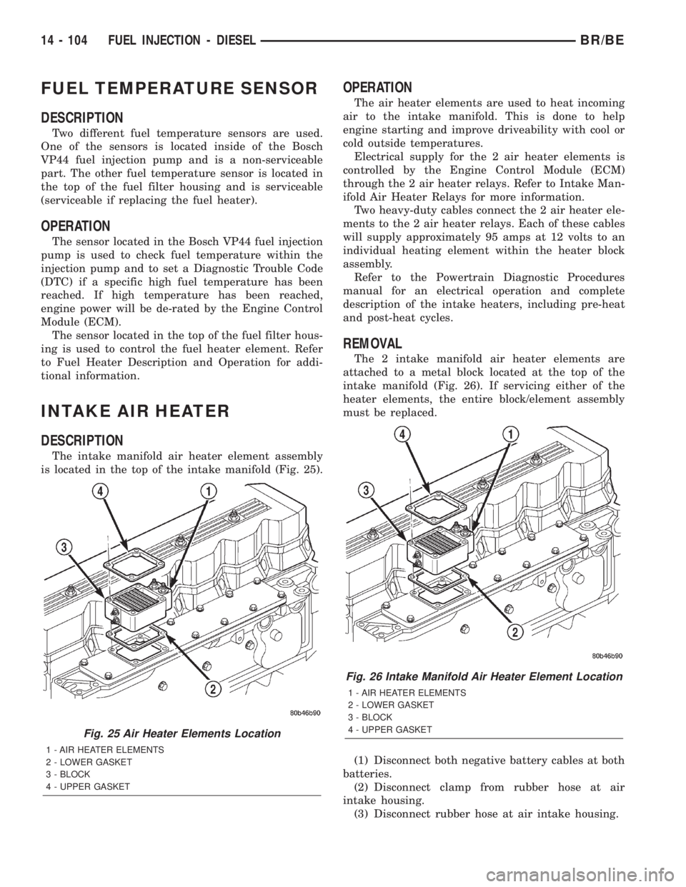
The intake manifold air heater element assembly
is located in the top of the intake manifold (Fig. 25).
OPERATION
The air heater elements are used to heat incoming
air to the intake manifold. This is done to help
engine starting and improve driveability with cool or
cold outside temperatures.
Electrical supply for the 2 air heater elements is
controlled by the Engine Control Module (ECM)
through the 2 air heater relays. Refer to Intake Man-
ifold Air Heater Relays for more information.
Two heavy-duty cables connect the 2 air heater ele-
ments to the 2 air heater relays. Each of these cables
will supply approximately 95 amps at 12 volts to an
individual heating element within the heater block
assembly.
Refer to the Powertrain Diagnostic Procedures
manual for an electrical operation and complete
description of the intake heaters, including pre-heat
and post-heat cycles.
REMOVAL
The 2 intake manifold air heater elements are
attached to a metal block located at the top of the
intake manifold (Fig. 26). If servicing either of the
heater elements, the entire block/element assembly
must be replaced.
(1) Disconnect both negative battery cables at both
batteries.
(2) Disconnect clamp from rubber hose at air
intake housing.
(3) Disconnect rubber hose at air intake housing.
Fig. 25 Air Heater Elements Location
1 - AIR HEATER ELEMENTS
2 - LOWER GASKET
3 - BLOCK
4 - UPPER GASKET
Fig. 26 Intake Manifold Air Heater Element Location
1 - AIR HEATER ELEMENTS
2 - LOWER GASKET
3 - BLOCK
4 - UPPER GASKET
14 - 104 FUEL INJECTION - DIESELBR/BE
Page 1404 of 2255
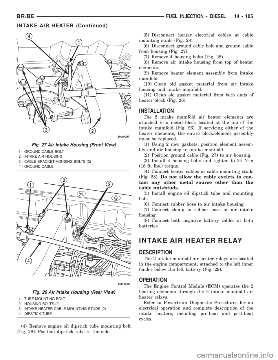
(4) Remove engine oil dipstick tube mounting bolt
(Fig. 28). Position dipstick tube to the side.(5) Disconnect heater electrical cables at cable
mounting studs (Fig. 28).
(6) Disconnect ground cable bolt and ground cable
from housing (Fig. 27).
(7) Remove 4 housing bolts (Fig. 28).
(8) Remove air intake housing from top of heater
elements.
(9) Remove heater element assembly from intake
manifold.
(10) Clean old gasket material from air intake
housing and intake manifold.
(11) Clean old gasket material from both ends of
heater block (Fig. 26).
INSTALLATION
The 2 intake manifold air heater elements are
attached to a metal block located at the top of the
intake manifold (Fig. 26). If servicing either of the
heater elements, the entire block/element assembly
must be replaced.
(1) Using 2 new gaskets, position element assem-
bly and air housing to intake manifold.
(2) Position ground cable (Fig. 27) to air housing.
(3) Install 4 housing bolts and tighten to 24 N´m
(18 ft. lbs.) torque.
(4) Connect heater cables at cable mounting studs
(Fig. 28).Do not allow the cable eyelets to con-
tact any other metal source other than the
cable nuts/studs.
(5) Install engine oil dipstick tube and mounting
bolt.
(6) Connect rubber hose to air intake housing.
(7) Connect clamp to rubber hose at air intake
housing.
(8) Connect both negative battery cables at both
batteries.
INTAKE AIR HEATER RELAY
DESCRIPTION
The 2 intake manifold air heater relays are located
in the engine compartment, attached to the left inner
fender below the left battery (Fig. 29).
OPERATION
The Engine Control Module (ECM) operates the 2
heating elements through the 2 intake manifold air
heater relays.
Refer to Powertrain Diagnostic Procedures for an
electrical operation and complete description of the
intake heaters, including pre-heat and post-heat
cycles.
Fig. 27 Air Intake Housing (Front View)
1 - GROUND CABLE BOLT
2 - INTAKE AIR HOUSING
3 - CABLE BRACKET HOUSING BOLTS (3)
4 - GROUND CABLE
Fig. 28 Air Intake Housing (Rear View)
1 - TUBE MOUNTING BOLT
2 - HOUSING BOLTS (2)
3 - INTAKE HEATER CABLE MOUNTING STUDS (2)
4 - DIPSTICK TUBE
BR/BEFUEL INJECTION - DIESEL 14 - 105
INTAKE AIR HEATER (Continued)
Page 1405 of 2255
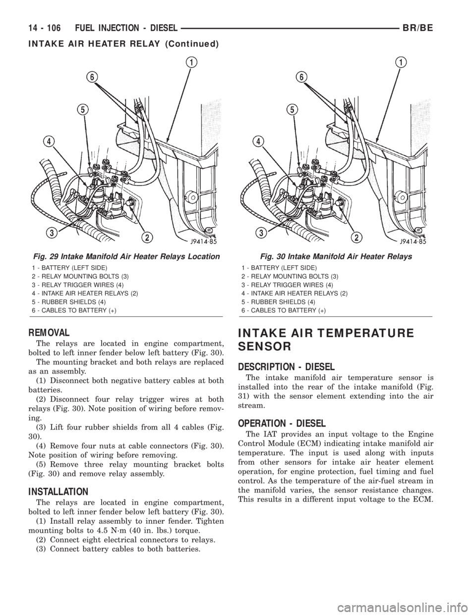
REMOVAL
The relays are located in engine compartment,
bolted to left inner fender below left battery (Fig. 30).
The mounting bracket and both relays are replaced
as an assembly.
(1) Disconnect both negative battery cables at both
batteries.
(2) Disconnect four relay trigger wires at both
relays (Fig. 30). Note position of wiring before remov-
ing.
(3) Lift four rubber shields from all 4 cables (Fig.
30).
(4) Remove four nuts at cable connectors (Fig. 30).
Note position of wiring before removing.
(5) Remove three relay mounting bracket bolts
(Fig. 30) and remove relay assembly.
INSTALLATION
The relays are located in engine compartment,
bolted to left inner fender below left battery (Fig. 30).
(1) Install relay assembly to inner fender. Tighten
mounting bolts to 4.5 N´m (40 in. lbs.) torque.
(2) Connect eight electrical connectors to relays.
(3) Connect battery cables to both batteries.
INTAKE AIR TEMPERATURE
SENSOR
DESCRIPTION - DIESEL
The intake manifold air temperature sensor is
installed into the rear of the intake manifold (Fig.
31) with the sensor element extending into the air
stream.
OPERATION - DIESEL
The IAT provides an input voltage to the Engine
Control Module (ECM) indicating intake manifold air
temperature. The input is used along with inputs
from other sensors for intake air heater element
operation, for engine protection, fuel timing and fuel
control. As the temperature of the air-fuel stream in
the manifold varies, the sensor resistance changes.
This results in a different input voltage to the ECM.
Fig. 29 Intake Manifold Air Heater Relays Location
1 - BATTERY (LEFT SIDE)
2 - RELAY MOUNTING BOLTS (3)
3 - RELAY TRIGGER WIRES (4)
4 - INTAKE AIR HEATER RELAYS (2)
5 - RUBBER SHIELDS (4)
6 - CABLES TO BATTERY (+)
Fig. 30 Intake Manifold Air Heater Relays
1 - BATTERY (LEFT SIDE)
2 - RELAY MOUNTING BOLTS (3)
3 - RELAY TRIGGER WIRES (4)
4 - INTAKE AIR HEATER RELAYS (2)
5 - RUBBER SHIELDS (4)
6 - CABLES TO BATTERY (+)
14 - 106 FUEL INJECTION - DIESELBR/BE
INTAKE AIR HEATER RELAY (Continued)
Page 1406 of 2255
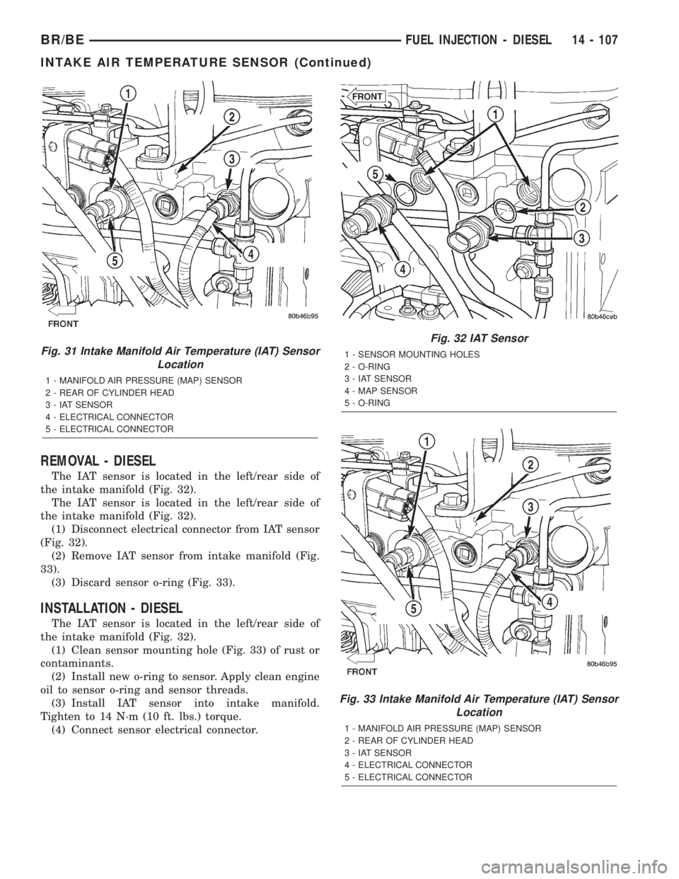
REMOVAL - DIESEL
The IAT sensor is located in the left/rear side of
the intake manifold (Fig. 32).
The IAT sensor is located in the left/rear side of
the intake manifold (Fig. 32).
(1) Disconnect electrical connector from IAT sensor
(Fig. 32).
(2) Remove IAT sensor from intake manifold (Fig.
33).
(3) Discard sensor o-ring (Fig. 33).
INSTALLATION - DIESEL
The IAT sensor is located in the left/rear side of
the intake manifold (Fig. 32).
(1) Clean sensor mounting hole (Fig. 33) of rust or
contaminants.
(2) Install new o-ring to sensor. Apply clean engine
oil to sensor o-ring and sensor threads.
(3) Install IAT sensor into intake manifold.
Tighten to 14 N´m (10 ft. lbs.) torque.
(4) Connect sensor electrical connector.
Fig. 31 Intake Manifold Air Temperature (IAT) Sensor
Location
1 - MANIFOLD AIR PRESSURE (MAP) SENSOR
2 - REAR OF CYLINDER HEAD
3 - IAT SENSOR
4 - ELECTRICAL CONNECTOR
5 - ELECTRICAL CONNECTOR
Fig. 32 IAT Sensor
1 - SENSOR MOUNTING HOLES
2 - O-RING
3 - IAT SENSOR
4 - MAP SENSOR
5 - O-RING
Fig. 33 Intake Manifold Air Temperature (IAT) Sensor
Location
1 - MANIFOLD AIR PRESSURE (MAP) SENSOR
2 - REAR OF CYLINDER HEAD
3 - IAT SENSOR
4 - ELECTRICAL CONNECTOR
5 - ELECTRICAL CONNECTOR
BR/BEFUEL INJECTION - DIESEL 14 - 107
INTAKE AIR TEMPERATURE SENSOR (Continued)
Page 1407 of 2255
MAP SENSOR
DESCRIPTION - DIESEL
The MAP sensor is installed into the rear of the
intake manifold (Fig. 31).
OPERATION - DIESEL
The MAP sensor reacts to air pressure changes in
the intake manifold. It provides an input voltage to
the Engine Control Module (ECM). As pressure
changes, MAP sensor voltage will change. The
change in MAP sensor voltage results in a different
input voltage to the ECM. The ECM uses this input,
along with inputs from other sensors to provide fuel
timing, fuel control and engine protection. Engine
protection is used to derate (drop power off) the
engine if turbocharger pressure becomes to high.
REMOVAL - DIESEL
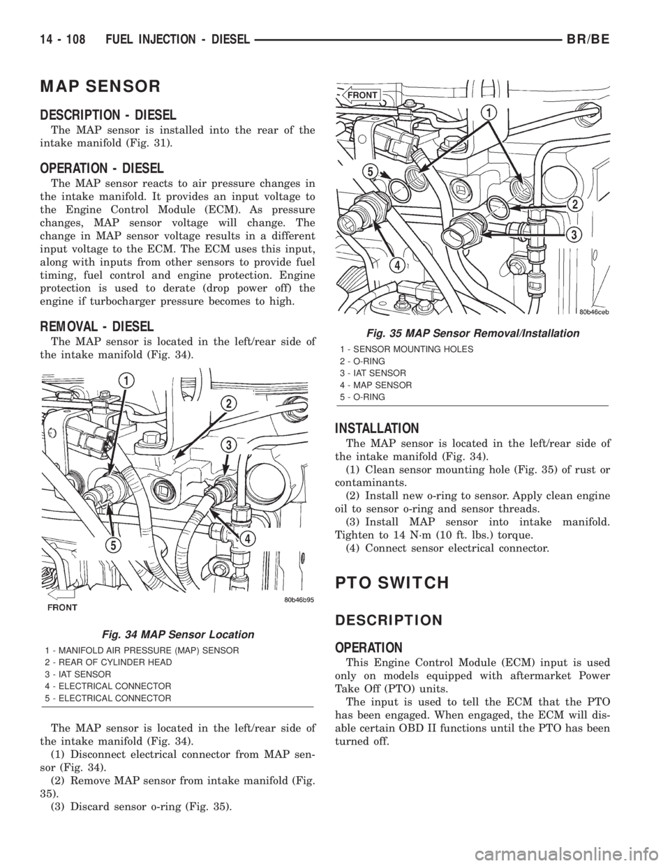
The MAP sensor is located in the left/rear side of
the intake manifold (Fig. 34).
The MAP sensor is located in the left/rear side of
the intake manifold (Fig. 34).
(1) Disconnect electrical connector from MAP sen-
sor (Fig. 34).
(2) Remove MAP sensor from intake manifold (Fig.
35).
(3) Discard sensor o-ring (Fig. 35).
INSTALLATION
The MAP sensor is located in the left/rear side of
the intake manifold (Fig. 34).
(1) Clean sensor mounting hole (Fig. 35) of rust or
contaminants.
(2) Install new o-ring to sensor. Apply clean engine
oil to sensor o-ring and sensor threads.
(3) Install MAP sensor into intake manifold.
Tighten to 14 N´m (10 ft. lbs.) torque.
(4) Connect sensor electrical connector.
PTO SWITCH
DESCRIPTION
OPERATION
This Engine Control Module (ECM) input is used
only on models equipped with aftermarket Power
Take Off (PTO) units.
The input is used to tell the ECM that the PTO
has been engaged. When engaged, the ECM will dis-
able certain OBD II functions until the PTO has been
turned off.
Fig. 34 MAP Sensor Location
1 - MANIFOLD AIR PRESSURE (MAP) SENSOR
2 - REAR OF CYLINDER HEAD
3 - IAT SENSOR
4 - ELECTRICAL CONNECTOR
5 - ELECTRICAL CONNECTOR
Fig. 35 MAP Sensor Removal/Installation
1 - SENSOR MOUNTING HOLES
2 - O-RING
3 - IAT SENSOR
4 - MAP SENSOR
5 - O-RING
14 - 108 FUEL INJECTION - DIESELBR/BE
Page 1408 of 2255
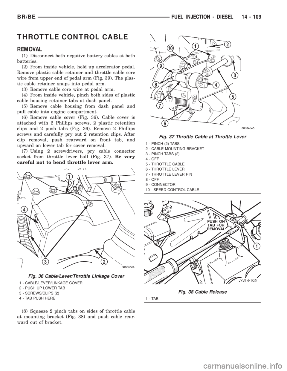
THROTTLE CONTROL CABLE
REMOVAL
(1) Disconnect both negative battery cables at both
batteries.
(2) From inside vehicle, hold up accelerator pedal.
Remove plastic cable retainer and throttle cable core
wire from upper end of pedal arm (Fig. 39). The plas-
tic cable retainer snaps into pedal arm.
(3) Remove cable core wire at pedal arm.
(4) From inside vehicle, pinch both sides of plastic
cable housing retainer tabs at dash panel.
(5) Remove cable housing from dash panel and
pull cable into engine compartment.
(6) Remove cable cover (Fig. 36). Cable cover is
attached with 2 Phillips screws, 2 plastic retention
clips and 2 push tabs (Fig. 36). Remove 2 Phillips
screws and carefully pry out 2 retention clips. After
clip removal, push rearward on front tab, and
upward on lower tab for cover removal.
(7) Using 2 screwdrivers, pry cable connector
socket from throttle lever ball (Fig. 37).Be very
careful not to bend throttle lever arm.
(8) Squeeze 2 pinch tabs on sides of throttle cable
at mounting bracket (Fig. 38) and push cable rear-
ward out of bracket.
Fig. 36 Cable/Lever/Throttle Linkage Cover
1 - CABLE/LEVER/LINKAGE COVER
2 - PUSH UP LOWER TAB
3 - SCREWS/CLIPS (2)
4 - TAB PUSH HERE
Fig. 37 Throttle Cable at Throttle Lever
1 - PINCH (2) TABS
2 - CABLE MOUNTING BRACKET
3 - PINCH TABS (2)
4 - OFF
5 - THROTTLE CABLE
6 - THROTTLE LEVER
7 - THROTTLE LEVER PIN
8 - OFF
9 - CONNECTOR
10 - SPEED CONTROL CABLE
Fig. 38 Cable Release
1-TAB
BR/BEFUEL INJECTION - DIESEL 14 - 109
Page 1409 of 2255
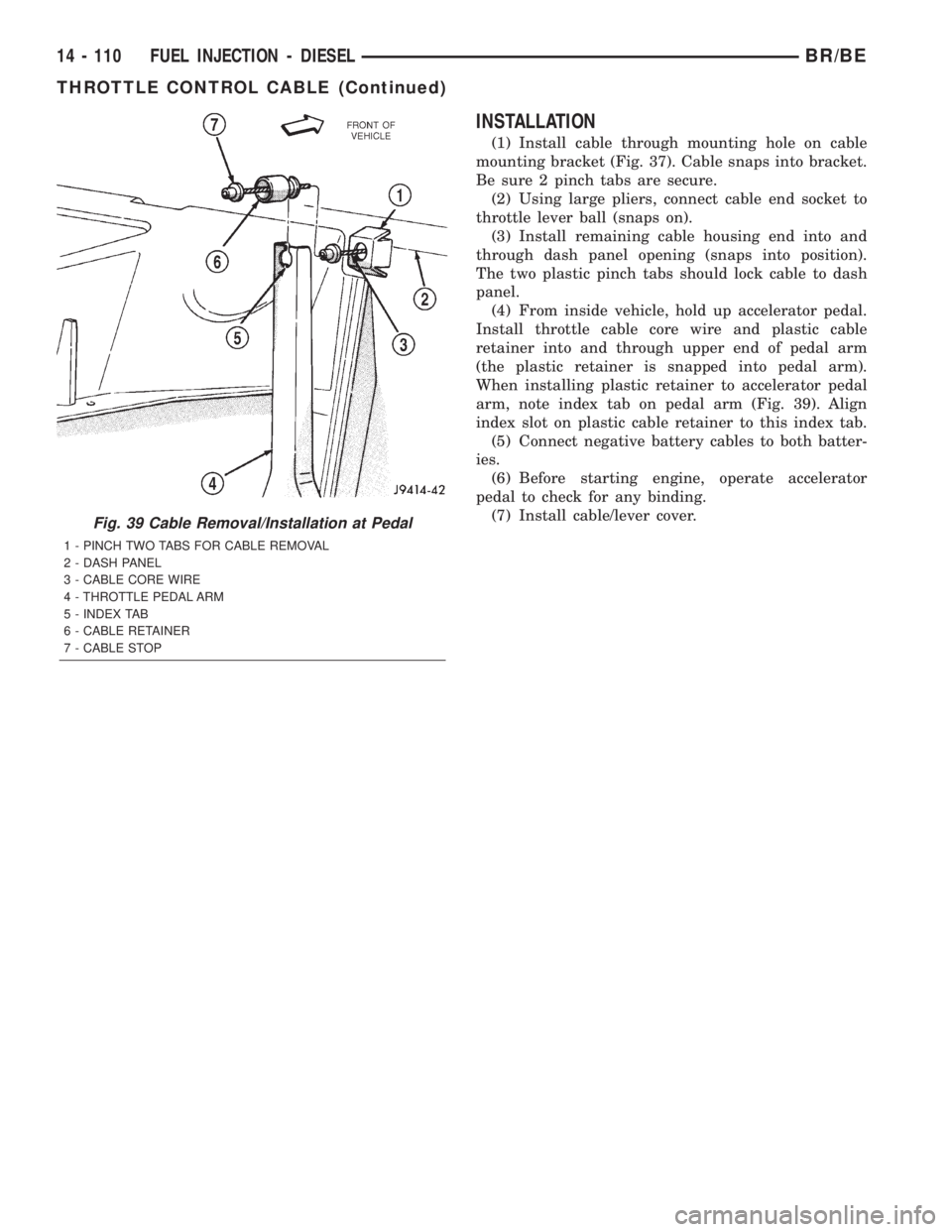
INSTALLATION
(1) Install cable through mounting hole on cable
mounting bracket (Fig. 37). Cable snaps into bracket.
Be sure 2 pinch tabs are secure.
(2) Using large pliers, connect cable end socket to
throttle lever ball (snaps on).
(3) Install remaining cable housing end into and
through dash panel opening (snaps into position).
The two plastic pinch tabs should lock cable to dash
panel.
(4) From inside vehicle, hold up accelerator pedal.
Install throttle cable core wire and plastic cable
retainer into and through upper end of pedal arm
(the plastic retainer is snapped into pedal arm).
When installing plastic retainer to accelerator pedal
arm, note index tab on pedal arm (Fig. 39). Align
index slot on plastic cable retainer to this index tab.
(5) Connect negative battery cables to both batter-
ies.
(6) Before starting engine, operate accelerator
pedal to check for any binding.
(7) Install cable/lever cover.
Fig. 39 Cable Removal/Installation at Pedal
1 - PINCH TWO TABS FOR CABLE REMOVAL
2 - DASH PANEL
3 - CABLE CORE WIRE
4 - THROTTLE PEDAL ARM
5 - INDEX TAB
6 - CABLE RETAINER
7 - CABLE STOP
14 - 110 FUEL INJECTION - DIESELBR/BE
THROTTLE CONTROL CABLE (Continued)
Page 1410 of 2255
STEERING
TABLE OF CONTENTS
page page
STEERING
DESCRIPTION..........................1
OPERATION............................1
DIAGNOSIS AND TESTING
DIAGNOSIS AND TESTING - POWER
STEERING SYSTEM....................2
DIAGNOSIS AND TESTING - POWER
STEERING FLOW AND PRESSURE........4COLUMN...............................6
GEAR.................................16
PUMP.................................33
LINKAGE - 2WD.........................40
LINKAGE - 4WD.........................42
STEERING
DESCRIPTION
The power steering system consist of a steering col-
umn, steering gear and hydraulic pump. The gear is
mounted to the frame rail and attaches to the steer-
ing linkage. The pump is a constant flow rate and
displacement vane-type pump. The pump supplies
hydraulic fluid pressure to the power steering gear
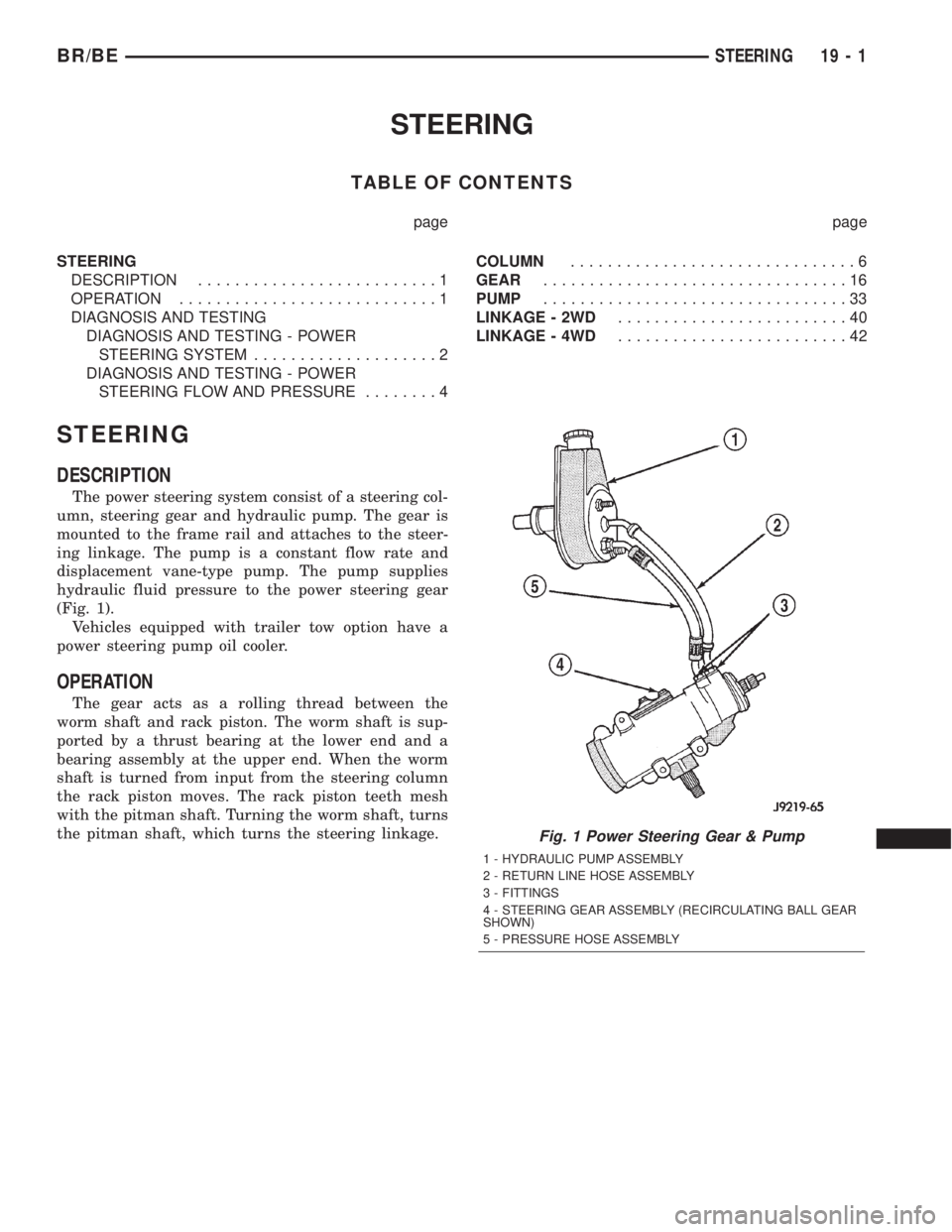
(Fig. 1).
Vehicles equipped with trailer tow option have a
power steering pump oil cooler.
OPERATION
The gear acts as a rolling thread between the
worm shaft and rack piston. The worm shaft is sup-
ported by a thrust bearing at the lower end and a
bearing assembly at the upper end. When the worm
shaft is turned from input from the steering column
the rack piston moves. The rack piston teeth mesh
with the pitman shaft. Turning the worm shaft, turns
the pitman shaft, which turns the steering linkage.
Fig. 1 Power Steering Gear & Pump
1 - HYDRAULIC PUMP ASSEMBLY
2 - RETURN LINE HOSE ASSEMBLY
3 - FITTINGS
4 - STEERING GEAR ASSEMBLY (RECIRCULATING BALL GEAR
SHOWN)
5 - PRESSURE HOSE ASSEMBLY
BR/BESTEERING 19 - 1