DODGE RAM 2002 Service Repair Manual
Manufacturer: DODGE, Model Year: 2002, Model line: RAM, Model: DODGE RAM 2002Pages: 2255, PDF Size: 62.07 MB
Page 1411 of 2255
DIAGNOSIS AND TESTING
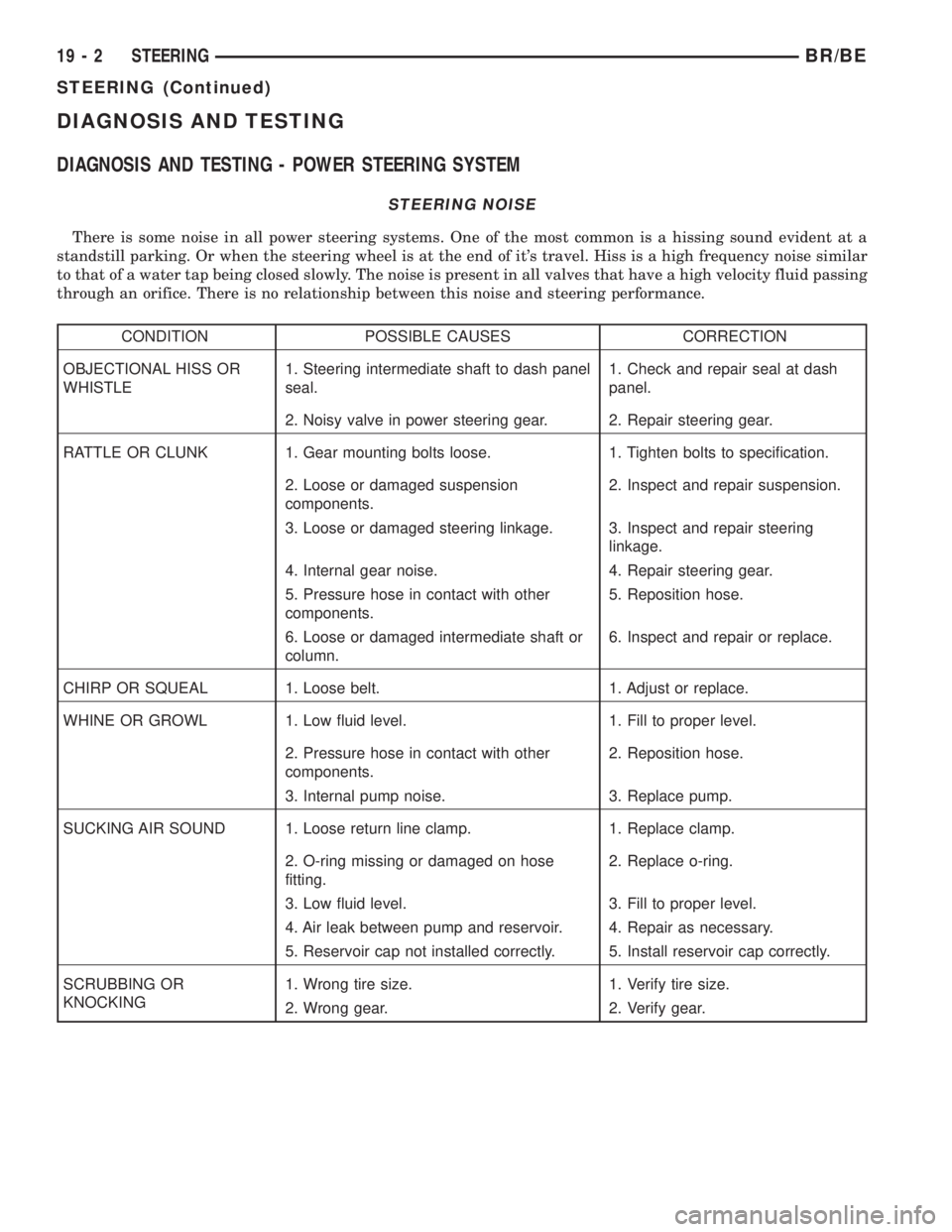
DIAGNOSIS AND TESTING - POWER STEERING SYSTEM
STEERING NOISE
There is some noise in all power steering systems. One of the most common is a hissing sound evident at a
standstill parking. Or when the steering wheel is at the end of it's travel. Hiss is a high frequency noise similar
to that of a water tap being closed slowly. The noise is present in all valves that have a high velocity fluid passing
through an orifice. There is no relationship between this noise and steering performance.
CONDITION POSSIBLE CAUSES CORRECTION
OBJECTIONAL HISS OR
WHISTLE1. Steering intermediate shaft to dash panel
seal.1. Check and repair seal at dash
panel.
2. Noisy valve in power steering gear. 2. Repair steering gear.
RATTLE OR CLUNK 1. Gear mounting bolts loose. 1. Tighten bolts to specification.
2. Loose or damaged suspension
components.2. Inspect and repair suspension.
3. Loose or damaged steering linkage. 3. Inspect and repair steering
linkage.
4. Internal gear noise. 4. Repair steering gear.
5. Pressure hose in contact with other
components.5. Reposition hose.
6. Loose or damaged intermediate shaft or
column.6. Inspect and repair or replace.
CHIRP OR SQUEAL 1. Loose belt. 1. Adjust or replace.
WHINE OR GROWL 1. Low fluid level. 1. Fill to proper level.
2. Pressure hose in contact with other
components.2. Reposition hose.
3. Internal pump noise. 3. Replace pump.
SUCKING AIR SOUND 1. Loose return line clamp. 1. Replace clamp.
2. O-ring missing or damaged on hose
fitting.2. Replace o-ring.
3. Low fluid level. 3. Fill to proper level.
4. Air leak between pump and reservoir. 4. Repair as necessary.
5. Reservoir cap not installed correctly. 5. Install reservoir cap correctly.
SCRUBBING OR
KNOCKING1. Wrong tire size. 1. Verify tire size.
2. Wrong gear. 2. Verify gear.
19 - 2 STEERINGBR/BE
STEERING (Continued)
Page 1412 of 2255
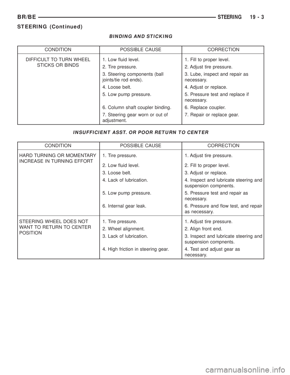
BINDING AND STICKING
CONDITION POSSIBLE CAUSE CORRECTION
DIFFICULT TO TURN WHEEL
STICKS OR BINDS1. Low fluid level. 1. Fill to proper level.
2. Tire pressure. 2. Adjust tire pressure.
3. Steering components (ball
joints/tie rod ends).3. Lube, inspect and repair as
necessary.
4. Loose belt. 4. Adjust or replace.
5. Low pump pressure. 5. Pressure test and replace if
necessary.
6. Column shaft coupler binding. 6. Replace coupler.
7. Steering gear worn or out of
adjustment.7. Repair or replace gear.
INSUFFICIENT ASST. OR POOR RETURN TO CENTER
CONDITION POSSIBLE CAUSE CORRECTION
HARD TURNING OR MOMENTARY
INCREASE IN TURNING EFFORT1. Tire pressure. 1. Adjust tire pressure.
2. Low fluid level. 2. Fill to proper level.
3. Loose belt. 3. Adjust or replace.
4. Lack of lubrication. 4. Inspect and lubricate steering and
suspension compnents.
5. Low pump pressure. 5. Pressure test and repair as
necessary.
6. Internal gear leak. 6. Pressure and flow test, and repair
as necessary.
STEERING WHEEL DOES NOT
WANT TO RETURN TO CENTER
POSITION1. Tire pressure. 1. Adjust tire pressure.
2. Wheel alignment. 2. Align front end.
3. Lack of lubrication. 3. Inspect and lubricate steering and
suspension compnents.
4. High friction in steering gear. 4. Test and adjust gear as
necessary.
BR/BESTEERING 19 - 3
STEERING (Continued)
Page 1413 of 2255
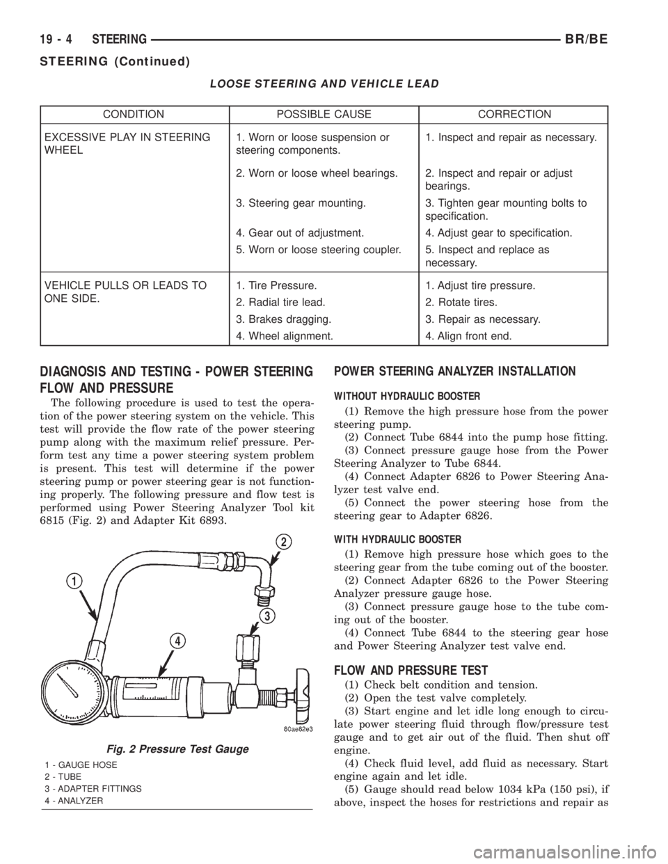
LOOSE STEERING AND VEHICLE LEAD
CONDITION POSSIBLE CAUSE CORRECTION
EXCESSIVE PLAY IN STEERING
WHEEL1. Worn or loose suspension or
steering components.1. Inspect and repair as necessary.
2. Worn or loose wheel bearings. 2. Inspect and repair or adjust
bearings.
3. Steering gear mounting. 3. Tighten gear mounting bolts to
specification.
4. Gear out of adjustment. 4. Adjust gear to specification.
5. Worn or loose steering coupler. 5. Inspect and replace as
necessary.
VEHICLE PULLS OR LEADS TO
ONE SIDE.1. Tire Pressure. 1. Adjust tire pressure.
2. Radial tire lead. 2. Rotate tires.
3. Brakes dragging. 3. Repair as necessary.
4. Wheel alignment. 4. Align front end.
DIAGNOSIS AND TESTING - POWER STEERING
FLOW AND PRESSURE
The following procedure is used to test the opera-
tion of the power steering system on the vehicle. This
test will provide the flow rate of the power steering
pump along with the maximum relief pressure. Per-
form test any time a power steering system problem
is present. This test will determine if the power
steering pump or power steering gear is not function-
ing properly. The following pressure and flow test is
performed using Power Steering Analyzer Tool kit
6815 (Fig. 2) and Adapter Kit 6893.
POWER STEERING ANALYZER INSTALLATION
WITHOUT HYDRAULIC BOOSTER
(1) Remove the high pressure hose from the power
steering pump.
(2) Connect Tube 6844 into the pump hose fitting.
(3) Connect pressure gauge hose from the Power
Steering Analyzer to Tube 6844.
(4) Connect Adapter 6826 to Power Steering Ana-
lyzer test valve end.
(5) Connect the power steering hose from the
steering gear to Adapter 6826.
WITH HYDRAULIC BOOSTER
(1) Remove high pressure hose which goes to the
steering gear from the tube coming out of the booster.
(2) Connect Adapter 6826 to the Power Steering
Analyzer pressure gauge hose.
(3) Connect pressure gauge hose to the tube com-
ing out of the booster.
(4) Connect Tube 6844 to the steering gear hose
and Power Steering Analyzer test valve end.
FLOW AND PRESSURE TEST
(1) Check belt condition and tension.
(2) Open the test valve completely.
(3) Start engine and let idle long enough to circu-
late power steering fluid through flow/pressure test
gauge and to get air out of the fluid. Then shut off
engine.
(4) Check fluid level, add fluid as necessary. Start
engine again and let idle.
(5) Gauge should read below 1034 kPa (150 psi), if
above, inspect the hoses for restrictions and repair as
Fig. 2 Pressure Test Gauge
1 - GAUGE HOSE
2 - TUBE
3 - ADAPTER FITTINGS
4 - ANALYZER
19 - 4 STEERINGBR/BE
STEERING (Continued)
Page 1414 of 2255
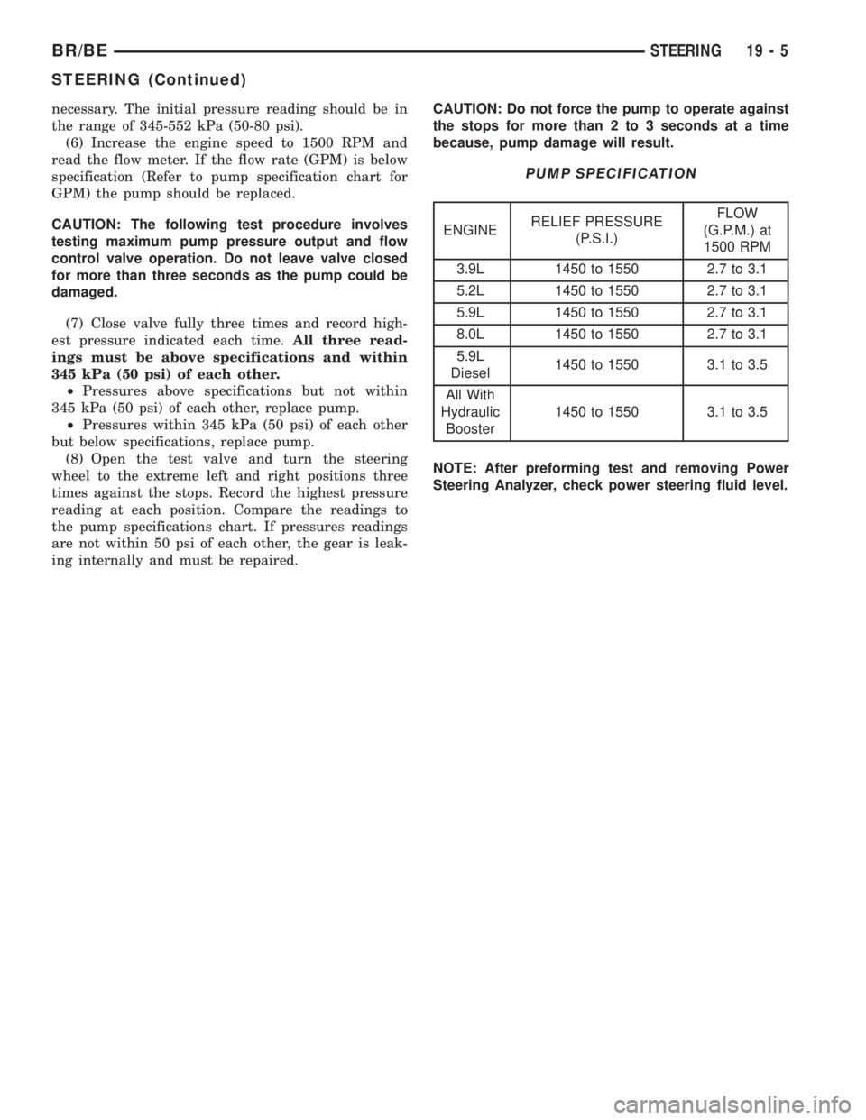
necessary. The initial pressure reading should be in
the range of 345-552 kPa (50-80 psi).
(6) Increase the engine speed to 1500 RPM and
read the flow meter. If the flow rate (GPM) is below
specification (Refer to pump specification chart for
GPM) the pump should be replaced.
CAUTION: The following test procedure involves
testing maximum pump pressure output and flow
control valve operation. Do not leave valve closed
for more than three seconds as the pump could be
damaged.
(7) Close valve fully three times and record high-
est pressure indicated each time.All three read-
ings must be above specifications and within
345 kPa (50 psi) of each other.
²Pressures above specifications but not within
345 kPa (50 psi) of each other, replace pump.
²Pressures within 345 kPa (50 psi) of each other
but below specifications, replace pump.
(8) Open the test valve and turn the steering
wheel to the extreme left and right positions three
times against the stops. Record the highest pressure
reading at each position. Compare the readings to
the pump specifications chart. If pressures readings
are not within 50 psi of each other, the gear is leak-
ing internally and must be repaired.CAUTION: Do not force the pump to operate against
the stops for more than 2 to 3 seconds at a time
because, pump damage will result.
PUMP SPECIFICATION
ENGINERELIEF PRESSURE
(P.S.I.)FLOW
(G.P.M.) at
1500 RPM
3.9L 1450 to 1550 2.7 to 3.1
5.2L 1450 to 1550 2.7 to 3.1
5.9L 1450 to 1550 2.7 to 3.1
8.0L 1450 to 1550 2.7 to 3.1
5.9L
Diesel1450 to 1550 3.1 to 3.5
All With
Hydraulic
Booster1450 to 1550 3.1 to 3.5
NOTE: After preforming test and removing Power
Steering Analyzer, check power steering fluid level.
BR/BESTEERING 19 - 5
STEERING (Continued)
Page 1415 of 2255
COLUMN
TABLE OF CONTENTS
page page
COLUMN
DESCRIPTION..........................6
OPERATION
SERVICE PRECAUTIONS................6
REMOVAL.............................6
INSTALLATION..........................8
SPECIFICATIONS
TORQUE CHART......................9
KEY-IN IGNITION SWITCH
DESCRIPTION..........................9
DIAGNOSIS AND TESTING - IGNITION
SWITCH AND KEY LOCK CYLINDER.......9
LOCK CYLINDER
REMOVAL.............................10INSTALLATION.........................10
IGNITION SWITCH
DESCRIPTION.........................11
OPERATION...........................11
DIAGNOSIS AND TESTING - IGNITION
SWITCH.............................11
REMOVAL.............................12
INSTALLATION.........................12
GEAR SHIFT LEVER
REMOVAL.............................14
INSTALLATION.........................15
STEERING WHEEL
REMOVAL.............................15
INSTALLATION.........................15
COLUMN
DESCRIPTION
The tilt and standard column (Fig. 1) has been
designed to be serviced as an assembly; less wiring,
switches, shrouds, steering wheel, etc. Most steering
column components can be serviced without remov-
ing the steering column from the vehicle.
OPERATION
SERVICE PRECAUTIONS
Safety goggles should be worn at all times when
working on steering columns.
To service the steering wheel, switches or the air-
bag, refer to the WARNINGS and CAUTIONS below.
WARNING: THE AIRBAG SYSTEM IS A SENSITIVE,
COMPLEX ELECTRO-MECHANICAL UNIT. BEFORE
ATTEMPTING TO DIAGNOSE, REMOVE OR INSTALL
THE AIRBAG SYSTEM COMPONENTS YOU MUST
FIRST DISCONNECT AND ISOLATE THE BATTERY
NEGATIVE (GROUND) CABLE. THEN WAIT TWO
MINUTES FOR THE SYSTEM CAPACITOR TO DIS-
CHARGE. FAILURE TO DO SO COULD RESULT IN
ACCIDENTAL DEPLOYMENT OF THE AIRBAG AND
POSSIBLE PERSONAL INJURY. THE FASTENERS,
SCREWS, AND BOLTS, ORIGINALLY USED FOR
THE AIRBAG COMPONENTS, HAVE SPECIAL COAT-INGS AND ARE SPECIFICALLY DESIGNED FOR THE
AIRBAG SYSTEM. THEY MUST NEVER BE
REPLACED WITH ANY SUBSTITUTES. ANYTIME A
NEW FASTENER IS NEEDED, REPLACE WITH THE
CORRECT FASTENERS PROVIDED IN THE SERVICE
PACKAGE OR FASTENERS LISTED IN THE PARTS
BOOKS.
CAUTION: Do not hammer on steering column shaft
or shift tube. This may cause the shaft/shift tube to
collapse or damage the bearing.
CAUTION: Do not attempt to remove the pivot pins
to disassemble the tilting mechanism. Do not
remove shaft lock plate, plate retainer, park lock
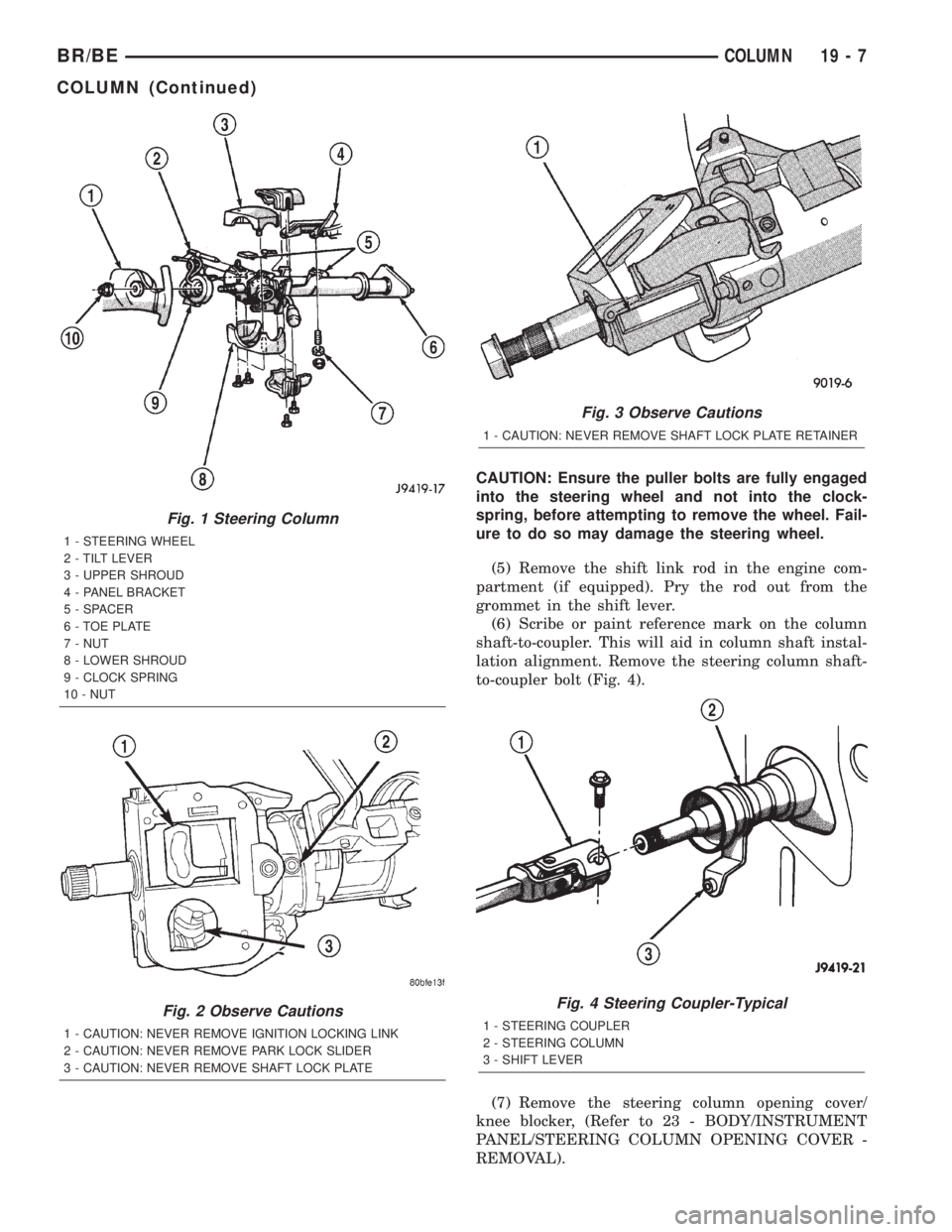
link or slider. This will damage the column (Fig. 2)
and (Fig. 3).
REMOVAL
(1) Position the front wheels straight ahead.
(2) Disconnect the negative (ground) cable from
the battery.
(3) Remove the airbag, (Refer to 8 - ELECTRICAL/
RESTRAINTS/DRIVER AIRBAG - REMOVAL).
(4) Remove the steering wheel with an appropriate
puller,(Refer to 19 - STEERING/COLUMN/STEER-
ING WHEEL - REMOVAL).
19 - 6 COLUMNBR/BE
Page 1416 of 2255
CAUTION: Ensure the puller bolts are fully engaged
into the steering wheel and not into the clock-
spring, before attempting to remove the wheel. Fail-
ure to do so may damage the steering wheel.
(5) Remove the shift link rod in the engine com-
partment (if equipped). Pry the rod out from the
grommet in the shift lever.
(6) Scribe or paint reference mark on the column
shaft-to-coupler. This will aid in column shaft instal-
lation alignment. Remove the steering column shaft-
to-coupler bolt (Fig. 4).
(7) Remove the steering column opening cover/
knee blocker, (Refer to 23 - BODY/INSTRUMENT
PANEL/STEERING COLUMN OPENING COVER -
REMOVAL).
Fig. 1 Steering Column
1 - STEERING WHEEL
2 - TILT LEVER
3 - UPPER SHROUD
4 - PANEL BRACKET
5 - SPACER
6 - TOE PLATE
7 - NUT
8 - LOWER SHROUD
9 - CLOCK SPRING
10 - NUT
Fig. 2 Observe Cautions
1 - CAUTION: NEVER REMOVE IGNITION LOCKING LINK
2 - CAUTION: NEVER REMOVE PARK LOCK SLIDER
3 - CAUTION: NEVER REMOVE SHAFT LOCK PLATE
Fig. 3 Observe Cautions
1 - CAUTION: NEVER REMOVE SHAFT LOCK PLATE RETAINER
Fig. 4 Steering Coupler-Typical
1 - STEERING COUPLER
2 - STEERING COLUMN
3 - SHIFT LEVER
BR/BECOLUMN 19 - 7
COLUMN (Continued)
Page 1417 of 2255
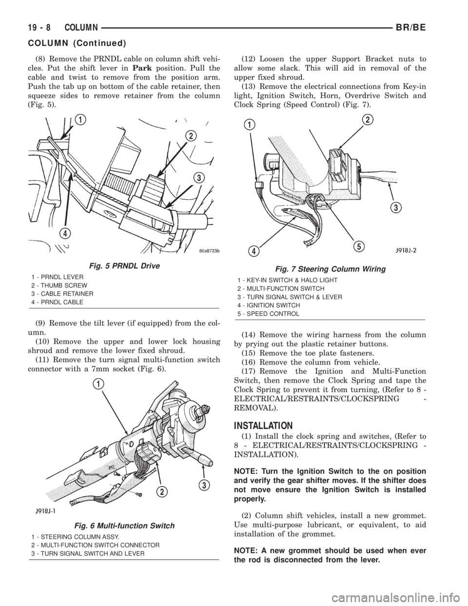
(8) Remove the PRNDL cable on column shift vehi-
cles. Put the shift lever inParkposition. Pull the
cable and twist to remove from the position arm.
Push the tab up on bottom of the cable retainer, then
squeeze sides to remove retainer from the column
(Fig. 5).
(9) Remove the tilt lever (if equipped) from the col-
umn.
(10) Remove the upper and lower lock housing
shroud and remove the lower fixed shroud.
(11) Remove the turn signal multi-function switch
connector with a 7mm socket (Fig. 6).(12) Loosen the upper Support Bracket nuts to
allow some slack. This will aid in removal of the
upper fixed shroud.
(13) Remove the electrical connections from Key-in
light, Ignition Switch, Horn, Overdrive Switch and
Clock Spring (Speed Control) (Fig. 7).
(14) Remove the wiring harness from the column
by prying out the plastic retainer buttons.
(15) Remove the toe plate fasteners.
(16) Remove the column from vehicle.
(17) Remove the Ignition and Multi-Function
Switch, then remove the Clock Spring and tape the
Clock Spring to prevent it from turning, (Refer to 8 -
ELECTRICAL/RESTRAINTS/CLOCKSPRING -
REMOVAL).
INSTALLATION
(1) Install the clock spring and switches, (Refer to
8 - ELECTRICAL/RESTRAINTS/CLOCKSPRING -
INSTALLATION).
NOTE: Turn the Ignition Switch to the on position
and verify the gear shifter moves. If the shifter does
not move ensure the Ignition Switch is installed
properly.
(2) Column shift vehicles, install a new grommet.
Use multi-purpose lubricant, or equivalent, to aid
installation of the grommet.
NOTE: A new grommet should be used when ever
the rod is disconnected from the lever.
Fig. 5 PRNDL Drive
1 - PRNDL LEVER
2 - THUMB SCREW
3 - CABLE RETAINER
4 - PRNDL CABLE
Fig. 6 Multi-function Switch
1 - STEERING COLUMN ASSY.
2 - MULTI-FUNCTION SWITCH CONNECTOR
3 - TURN SIGNAL SWITCH AND LEVER
Fig. 7 Steering Column Wiring
1 - KEY-IN SWITCH & HALO LIGHT
2 - MULTI-FUNCTION SWITCH
3 - TURN SIGNAL SWITCH & LEVER
4 - IGNITION SWITCH
5 - SPEED CONTROL
19 - 8 COLUMNBR/BE
COLUMN (Continued)
Page 1418 of 2255
(3) Remove the shipping lock pin if necessary.
(4) Install the column through the floor pan.
(5) Position the column bracket breakaway cap-
sules on the mounting studs. Install, butloose
assemblethe two upper bracket nuts.
(6) With the front wheels in the straight-ahead
position. Align steering column shaft to the coupler.
Install anewpinch bolt and tighten to 49 N´m (36
ft. lbs.).
(7) Clip the wiring harness on the steering column.
Connect the multi- function switch wiring and
tighten with 7mm socket.
(8) Install the upper fixed shroud.
(9) Be sure both breakaway capsules are fully
seated in the slots in the column support bracket.
Pull the column rearward then tighten upper bracket
nuts to 12 N´m (105 in. lbs.).
(10) Tighten the toe plate to floor pan attaching
nuts to 22.5 N´m (200 in. lbs.).
(11) Install the wiring connections to the column.
Install the lower fixed shroud.
(12) Column shift vehicles, install the PRNDL
driver cable. Place shifter in Park position. If indica-tor needs adjusting, turn thumb screw on cable
retainer to adjust cable.
(13) Install the lock housing shrouds. Install the
tilt lever (if equipped).
(14) Install the knee blocker and steering column
opening cover, (Refer to 23 - BODY/INSTRUMENT
PANEL/STEERING COLUMN OPENING COVER -
INSTALLATION).
(15) Install steering wheel and tighten nut to 61
N´m (45 ft. lbs.), (Refer to 19 - STEERING/COL-
UMN/STEERING WHEEL - INSTALLATION).
(16) Install the airbag, (Refer to 8 - ELECTRICAL/
RESTRAINTS/DRIVER AIRBAG - INSTALLATION).
(17) Column shift vehicles, connect the shift link
rod to the transmission shift lever. Use multi-purpose
lubricant, or an equivalent product, to aid the instal-
lation.
(18) Install the battery ground (negative) cable.
(19) Verify operation of the automatic transmission
shift linkage and adjust as necessary, (Refer to 21 -
TRANSMISSION/TRANSAXLE/AUTOMATIC -
44RE/GEAR SHIFT CABLE - ADJUSTMENTS).
SPECIFICATIONS
TORQUE CHART
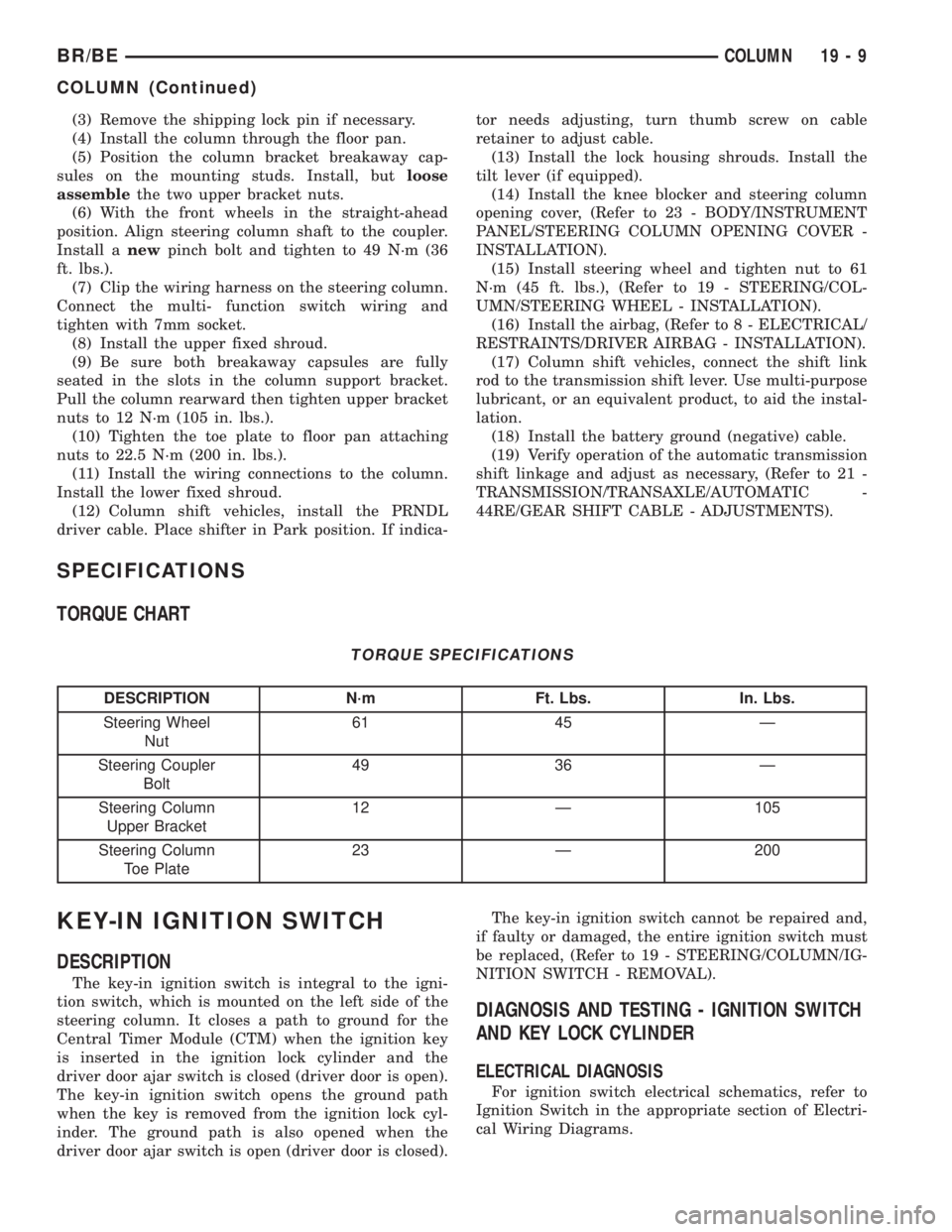
TORQUE SPECIFICATIONS
DESCRIPTION N´m Ft. Lbs. In. Lbs.
Steering Wheel
Nut61 45 Ð
Steering Coupler
Bolt49 36 Ð
Steering Column
Upper Bracket12 Ð 105
Steering Column
Toe Plate23 Ð 200
KEY-IN IGNITION SWITCH
DESCRIPTION
The key-in ignition switch is integral to the igni-
tion switch, which is mounted on the left side of the
steering column. It closes a path to ground for the
Central Timer Module (CTM) when the ignition key
is inserted in the ignition lock cylinder and the
driver door ajar switch is closed (driver door is open).
The key-in ignition switch opens the ground path
when the key is removed from the ignition lock cyl-
inder. The ground path is also opened when the
driver door ajar switch is open (driver door is closed).The key-in ignition switch cannot be repaired and,
if faulty or damaged, the entire ignition switch must
be replaced, (Refer to 19 - STEERING/COLUMN/IG-
NITION SWITCH - REMOVAL).
DIAGNOSIS AND TESTING - IGNITION SWITCH
AND KEY LOCK CYLINDER
ELECTRICAL DIAGNOSIS
For ignition switch electrical schematics, refer to
Ignition Switch in the appropriate section of Electri-
cal Wiring Diagrams.
BR/BECOLUMN 19 - 9
COLUMN (Continued)
Page 1419 of 2255
MECHANICAL DIAGNOSIS (KEY DIFFICULT TO
ROTATE)
Vehicles equipped with an automatic trans-
mission and a floor mounted shifter:a cable is
used to connect the interlock device in the steering
column assembly, to the transmission floor shift
lever. This interlock device is used to lock the trans-
mission shifter in the PARK position when the key
lock cylinder is rotated to the LOCKED or ACCES-
SORY position. The interlock device within the steer-
ing column is not serviceable. If repair is necessary,
the steering column assembly must be replaced.
(Refer to 19 - STEERING/COLUMN - REMOVAL).
If the ignition key is difficult to rotate to or from
the LOCK or ACCESSORY position, it may not be
the fault of the key cylinder or the steering column
components. The brake transmission shift interlock
cable may be out of adjustment. Refer to Brake
Transmission Shift Interlock Cable Adjustment in
Transmissions for adjustment procedures.
Vehicles equipped with an automatic trans-
mission and a steering column mounted shifter:
an interlock device is located within the steering col-
umn. This interlock device is used to lock the trans-
mission shifter in the PARK position when the key
lock cylinder is in the LOCKED or ACCESSORY
position. If it is difficult to rotate the key to or from
the LOCK or ACCESSORY position, the interlock
device within the steering column may be defective.
This device is not serviceable. If repair is necessary,
the steering column assembly must be replaced.
(Refer to 19 - STEERING/COLUMN - REMOVAL).
Vehicles equipped with a manual transmis-
sion and a floor mounted shifter:on certain mod-
els, a lever is located on the steering column behind
the ignition key lock cylinder. The lever must be
manually operated to allow rotation of the ignition
key lock cylinder to the LOCK or ACCESSORY posi-
tion. If it is difficult to rotate the key to the LOCK or
ACCESSORY position, the lever mechanism may be
defective. This mechanism is not serviceable. If
repair is necessary, the steering column assembly
must be replaced. (Refer to 19 - STEERING/COL-
UMN - REMOVAL).
On other models, the ignition key cylinder must be
depressed to allow it to be rotated into the LOCK or
ACCESSORY position. If it is difficult to rotate the
key to the LOCK or ACCESSORY position, the lock
mechanism within the steering column may be defec-
tive. This mechanism is not serviceable. If repair is
necessary, the steering column assembly must be
replaced. (Refer to 19 - STEERING/COLUMN -
REMOVAL).
LOCK CYLINDER
REMOVAL
The ignition key must be in the key cylinder for
cylinder removal.
(1) Disconnect negative cable from battery.
(2) If equipped with tilt column, remove tilt lever
by turning it counterclockwise.
(3) Remove upper and lower covers (shrouds) from
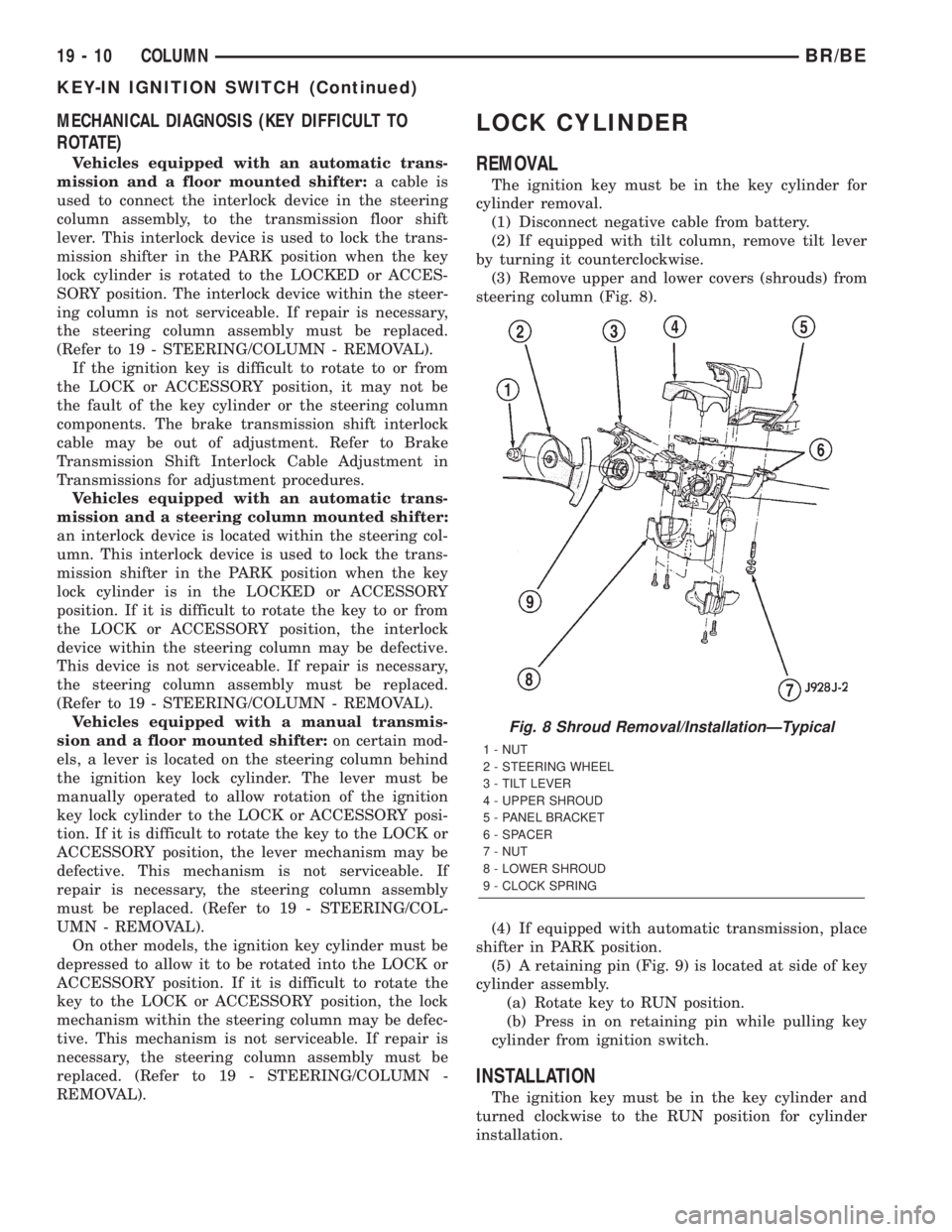
steering column (Fig. 8).
(4) If equipped with automatic transmission, place
shifter in PARK position.
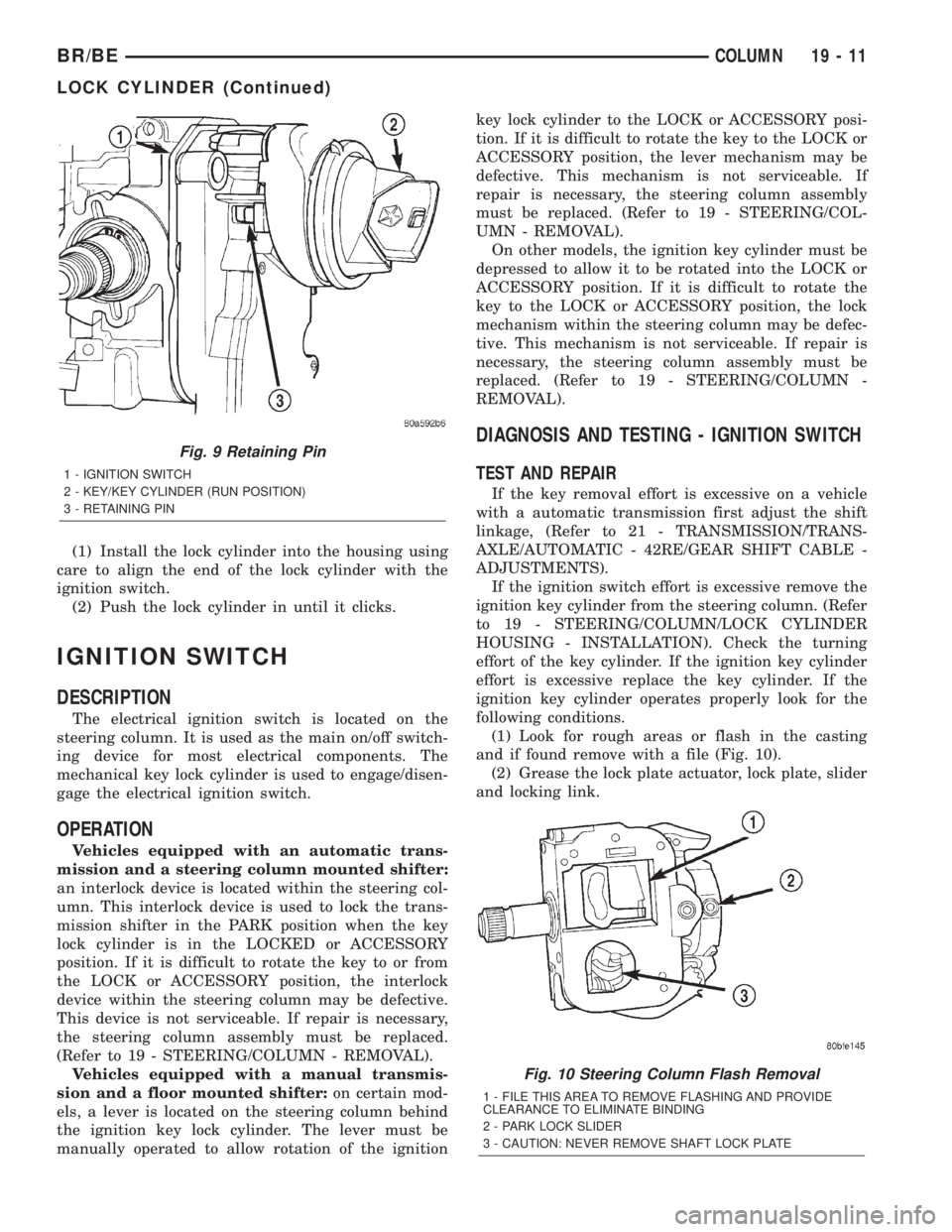
(5) A retaining pin (Fig. 9) is located at side of key
cylinder assembly.
(a) Rotate key to RUN position.
(b) Press in on retaining pin while pulling key
cylinder from ignition switch.
INSTALLATION
The ignition key must be in the key cylinder and
turned clockwise to the RUN position for cylinder
installation.
Fig. 8 Shroud Removal/InstallationÐTypical
1 - NUT
2 - STEERING WHEEL
3 - TILT LEVER
4 - UPPER SHROUD
5 - PANEL BRACKET
6 - SPACER
7 - NUT
8 - LOWER SHROUD
9 - CLOCK SPRING
19 - 10 COLUMNBR/BE
KEY-IN IGNITION SWITCH (Continued)
Page 1420 of 2255
(1) Install the lock cylinder into the housing using
care to align the end of the lock cylinder with the
ignition switch.
(2) Push the lock cylinder in until it clicks.
IGNITION SWITCH
DESCRIPTION
The electrical ignition switch is located on the
steering column. It is used as the main on/off switch-
ing device for most electrical components. The
mechanical key lock cylinder is used to engage/disen-
gage the electrical ignition switch.
OPERATION
Vehicles equipped with an automatic trans-
mission and a steering column mounted shifter:
an interlock device is located within the steering col-
umn. This interlock device is used to lock the trans-
mission shifter in the PARK position when the key
lock cylinder is in the LOCKED or ACCESSORY
position. If it is difficult to rotate the key to or from
the LOCK or ACCESSORY position, the interlock
device within the steering column may be defective.
This device is not serviceable. If repair is necessary,
the steering column assembly must be replaced.
(Refer to 19 - STEERING/COLUMN - REMOVAL).
Vehicles equipped with a manual transmis-
sion and a floor mounted shifter:on certain mod-
els, a lever is located on the steering column behind
the ignition key lock cylinder. The lever must be
manually operated to allow rotation of the ignitionkey lock cylinder to the LOCK or ACCESSORY posi-
tion. If it is difficult to rotate the key to the LOCK or
ACCESSORY position, the lever mechanism may be
defective. This mechanism is not serviceable. If
repair is necessary, the steering column assembly
must be replaced. (Refer to 19 - STEERING/COL-
UMN - REMOVAL).
On other models, the ignition key cylinder must be
depressed to allow it to be rotated into the LOCK or
ACCESSORY position. If it is difficult to rotate the
key to the LOCK or ACCESSORY position, the lock
mechanism within the steering column may be defec-
tive. This mechanism is not serviceable. If repair is
necessary, the steering column assembly must be
replaced. (Refer to 19 - STEERING/COLUMN -
REMOVAL).
DIAGNOSIS AND TESTING - IGNITION SWITCH
TEST AND REPAIR
If the key removal effort is excessive on a vehicle
with a automatic transmission first adjust the shift
linkage, (Refer to 21 - TRANSMISSION/TRANS-
AXLE/AUTOMATIC - 42RE/GEAR SHIFT CABLE -
ADJUSTMENTS).
If the ignition switch effort is excessive remove the
ignition key cylinder from the steering column. (Refer
to 19 - STEERING/COLUMN/LOCK CYLINDER
HOUSING - INSTALLATION). Check the turning
effort of the key cylinder. If the ignition key cylinder
effort is excessive replace the key cylinder. If the
ignition key cylinder operates properly look for the
following conditions.
(1) Look for rough areas or flash in the casting
and if found remove with a file (Fig. 10).
(2) Grease the lock plate actuator, lock plate, slider
and locking link.
Fig. 9 Retaining Pin
1 - IGNITION SWITCH
2 - KEY/KEY CYLINDER (RUN POSITION)
3 - RETAINING PIN
Fig. 10 Steering Column Flash Removal
1 - FILE THIS AREA TO REMOVE FLASHING AND PROVIDE
CLEARANCE TO ELIMINATE BINDING
2 - PARK LOCK SLIDER
3 - CAUTION: NEVER REMOVE SHAFT LOCK PLATE
BR/BECOLUMN 19 - 11
LOCK CYLINDER (Continued)