DODGE RAM 2003 Service Repair Manual
Manufacturer: DODGE, Model Year: 2003, Model line: RAM, Model: DODGE RAM 2003Pages: 2895, PDF Size: 83.15 MB
Page 2101 of 2895
REMOVAL
(1) Remove transmission and torque converter
from vehicle.
(2) Place a suitable drain pan under the converter
housing end of the transmission.
CAUTION: Verify that transmission is secure on the
lifting device or work surface, the center of gravity
of the transmission will shift when the torque con-
verter is removed creating an unstable condition.
The torque converter is a heavy unit. Use caution
when separating the torque converter from the
transmission.
(3) Pull the torque converter forward until the cen-
ter hub clears the oil pump seal.
(4) Separate the torque converter from the trans-
mission.
INSTALLATION
Check converter hub and drive notches for sharp
edges, burrs, scratches, or nicks. Polish the hub and
notches with 320/400 grit paper or crocus cloth if nec-
essary. The hub must be smooth to avoid damaging
the pump seal at installation.
(1) Lubricate oil pump seal lip with transmission
fluid.
(2) Place torque converter in position on transmis-
sion.
CAUTION: Do not damage oil pump seal or bushing
while inserting torque converter into the front of the
transmission.
(3)
Align torque converter to oil pump seal opening.
(4) Insert torque converter hub into oil pump.
(5) While pushing torque converter inward, rotate
converter until converter is fully seated in the oil
pump gears.
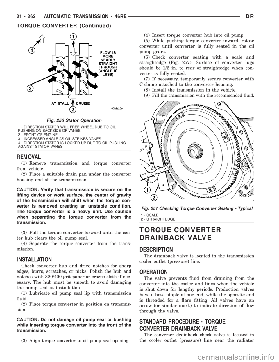
(6) Check converter seating with a scale and
straightedge (Fig. 257). Surface of converter lugs
should be 1/2 in. to rear of straightedge when con-
verter is fully seated.
(7) If necessary, temporarily secure converter with
C-clamp attached to the converter housing.
(8) Install the transmission in the vehicle.
(9)
Fill the transmission with the recommended fluid.
TORQUE CONVERTER
DRAINBACK VALVE
DESCRIPTION
The drainback valve is located in the transmission
cooler outlet (pressure) line.
OPERATION
The valve prevents fluid from draining from the
converter into the cooler and lines when the vehicle
is shut down for lengthy periods. Production valves
have a hose nipple at one end, while the opposite end
is threaded for a flare fitting. All valves have an
arrow (or similar mark) to indicate direction of flow
through the valve.
STANDARD PROCEDURE - TORQUE
CONVERTER DRAINBACK VALVE
The converter drainback check valve is located in
the cooler outlet (pressure) line near the radiator
Fig. 256 Stator Operation
1 - DIRECTION STATOR WILL FREE WHEEL DUE TO OIL
PUSHING ON BACKSIDE OF VANES
2 - FRONT OF ENGINE
3 - INCREASED ANGLE AS OIL STRIKES VANES
4 - DIRECTION STATOR IS LOCKED UP DUE TO OIL PUSHING
AGAINST STATOR VANES
Fig. 257 Checking Torque Converter Seating - Typical
1 - SCALE
2 - STRAIGHTEDGE
21 - 262 AUTOMATIC TRANSMISSION - 46REDR
TORQUE CONVERTER (Continued)
Page 2102 of 2895
tank. The valve prevents fluid drainback when the
vehicle is parked for lengthy periods. The valve check
ball is spring loaded and has an opening pressure of
approximately 2 psi.
The valve is serviced as an assembly; it is not repair-
able. Do not clean the valve if restricted, or contami-
nated by sludge, or debris. If the valve fails, or if a
transmission malfunction occurs that generates signifi-
cant amounts of sludge and/or clutch particles and
metal shavings, the valve must be replaced.
If the valve is restricted, installed backwards, or in
the wrong line, it will cause an overheating condition
and possible transmission failure.
CAUTION: The drainback valve is a one-way flow
device. It must be properly oriented in terms of flow
direction for the cooler to function properly. The
valve must be installed in the pressure line. Other-
wise flow will be blocked and would cause an over-
heating condition and eventual transmission failure.
TRANSMISSION RANGE
SENSOR
DESCRIPTION
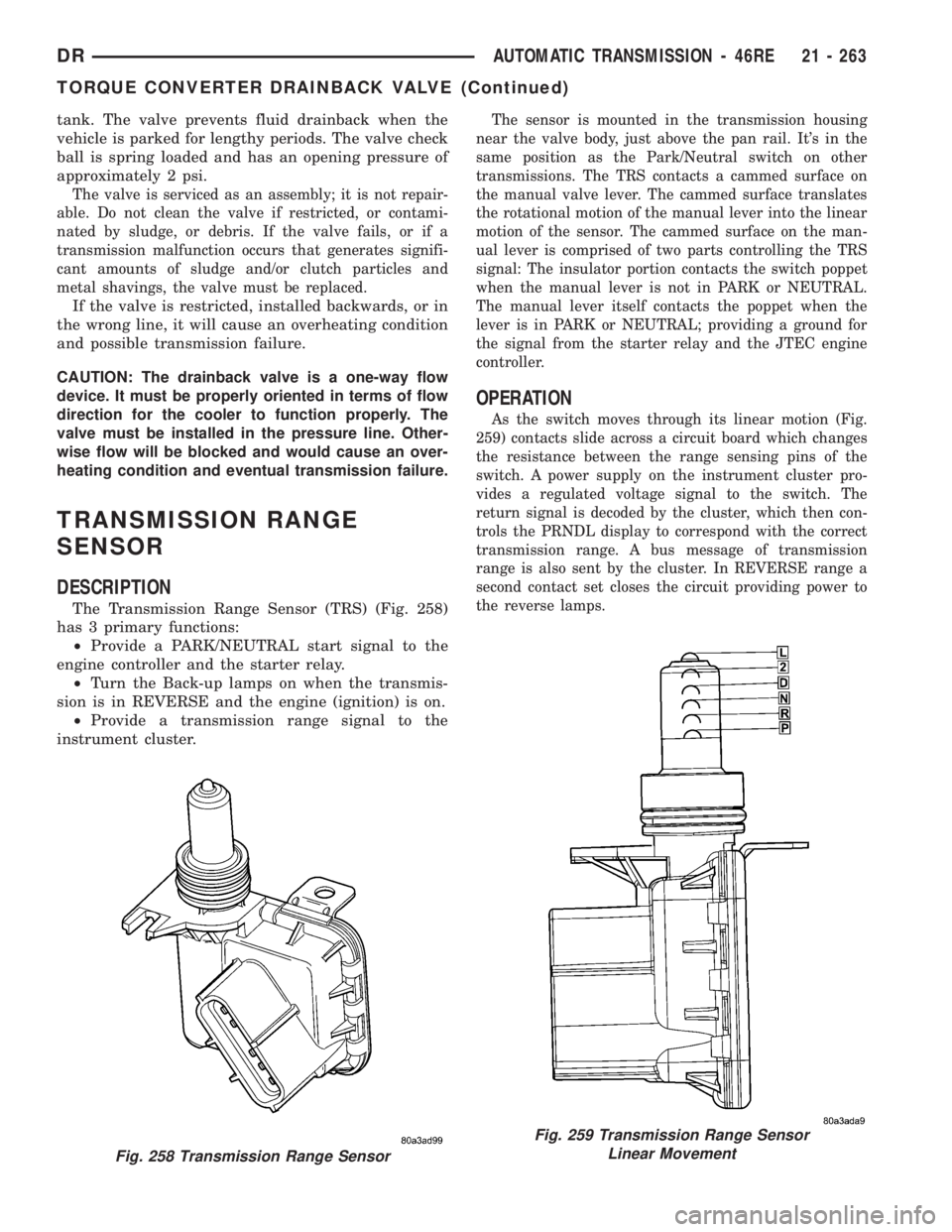
The Transmission Range Sensor (TRS) (Fig. 258)
has 3 primary functions:
²Provide a PARK/NEUTRAL start signal to the
engine controller and the starter relay.
²Turn the Back-up lamps on when the transmis-
sion is in REVERSE and the engine (ignition) is on.
²Provide a transmission range signal to the
instrument cluster.
The sensor is mounted in the transmission housing
near the valve body, just above the pan rail. It's in the
same position as the Park/Neutral switch on other
transmissions. The TRS contacts a cammed surface on
the manual valve lever. The cammed surface translates
the rotational motion of the manual lever into the linear
motion of the sensor. The cammed surface on the man-
ual lever is comprised of two parts controlling the TRS
signal: The insulator portion contacts the switch poppet
when the manual lever is not in PARK or NEUTRAL.
The manual lever itself contacts the poppet when the
lever is in PARK or NEUTRAL; providing a ground for
the signal from the starter relay and the JTEC engine
controller.
OPERATION
As the switch moves through its linear motion (Fig.
259) contacts slide across a circuit board which changes
the resistance between the range sensing pins of the
switch. A power supply on the instrument cluster pro-
vides a regulated voltage signal to the switch. The
return signal is decoded by the cluster, which then con-
trols the PRNDL display to correspond with the correct
transmission range. A bus message of transmission
range is also sent by the cluster. In REVERSE range a
second contact set closes the circuit providing power to
the reverse lamps.
Fig. 258 Transmission Range Sensor
Fig. 259 Transmission Range Sensor
Linear Movement
DRAUTOMATIC TRANSMISSION - 46RE 21 - 263
TORQUE CONVERTER DRAINBACK VALVE (Continued)
Page 2103 of 2895
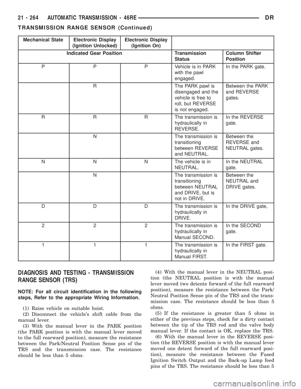
Mechanical State Electronic Display
(Ignition Unlocked)Electronic Display
(Ignition On)
Indicated Gear Position Transmission
StatusColumn Shifter
Position
P P P Vehicle is in PARK
with the pawl
engaged.In the PARK gate.
R The PARK pawl is
disengaged and the
vehicle is free to
roll, but REVERSE
is not engaged.Between the PARK
and REVERSE
gates.
R R R The transmission is
hydraulically in
REVERSE.In the REVERSE
gate.
N The transmission is
transitioning
between REVERSE
and NEUTRAL.Between the
REVERSE and
NEUTRAL gates.
N N N The vehicle is in
NEUTRAL.In the NEUTRAL
gate.
N The transmission is
transitioning
between NEUTRAL
and DRIVE, but is
not in DRIVE.Between the
NEUTRAL and
DRIVE gates.
D D D The transmission is
hydraulically in
DRIVE.In the DRIVE gate,
2 2 2 The transmission is
hydraulically in
Manual SECOND.In the SECOND
gate.
1 1 1 The transmission is
hydraulically in
Manual FIRST.In the FIRST gate.
DIAGNOSIS AND TESTING - TRANSMISSION
RANGE SENSOR (TRS)
NOTE: For all circuit identification in the following
steps, Refer to the appropriate Wiring Information.
(1) Raise vehicle on suitable hoist.
(2) Disconnect the vehicle's shift cable from the
manual lever.
(3) With the manual lever in the PARK position
(the PARK position is with the manual lever moved
to the full rearward position), measure the resistance
between the Park/Neutral Position Sense pin of the
TRS and the transmission case. The resistance
should be less than 5 ohms.(4) With the manual lever in the NEUTRAL posi-
tion (the NEUTRAL position is with the manual
lever moved two detents forward of the full rearward
position), measure the resistance between the Park/
Neutral Position Sense pin of the TRS and the trans-
mission case. The resistance should be less than 5
ohms.
(5) If the resistance is greater than 5 ohms in
either of the previous steps, check for a dirty contact
between the tip of the TRS rod and the valve body
manual lever. If the contact is OK, replace the TRS.
(6) With the manual lever in the REVERSE posi-
tion (the REVERSE position is with the manual lever
moved one detent forward of the full rearward posi-
tion), measure the resistance between the Fused
Ignition Switch Output and the Back-up Lamp feed
pins of the TRS. The resistance should be less than 5
21 - 264 AUTOMATIC TRANSMISSION - 46REDR
TRANSMISSION RANGE SENSOR (Continued)
Page 2104 of 2895
ohms. If the resistance is greater than 5 ohms,
replace the TRS.
(7) With the manual lever in the PARK position
(the PARK position is with the manual lever moved
to the full rearward position), measure the resistance
between the Transmission Range Sensor MUX and
the Transmission Range Sensor 5V Supply pins of
the TRS. The resistance should be 522.2 ohms. If the
resistance is not correct, replace the TRS.
(8) With the manual lever in the REVERSE posi-
tion (the REVERSE position is with the manual lever
moved one detent forward of the full rearward posi-
tion), measure the resistance between the Transmis-
sion Range Sensor MUX and the Transmission Range
Sensor 5V Supply pins of the TRS. The resistance
should be 206.2 ohms. If the resistance is not correct,
replace the TRS.
(9) With the manual lever in the NEUTRAL posi-
tion (the NEUTRAL position is with the manual
lever moved two detents forward of the full rearward
position), measure the resistance between the Trans-
mission Range Sensor MUX and the Transmission
Range Sensor 5V Supply pins of the TRS. The resis-
tance should be 108.6 ohms. If the resistance is not
correct, replace the TRS.
(10) With the manual lever in the DRIVE position
(the DRIVE position is with the manual lever moved
three detents forward of the full rearward position),
measure the resistance between the Transmission
Range Sensor MUX and the Transmission Range
Sensor 5V Supply pins of the TRS. The resistance
should be 59.9 ohms. If the resistance is not correct,
replace the TRS.
(11) With the manual lever in the SECOND posi-
tion (the SECOND position is with the manual lever
moved one detent rearward of the full forward posi-
tion), measure the resistance between the Transmis-
sion Range Sensor MUX and the Back-up Lamp feed
pins of the TRS. The resistance should be 31.9 ohms.
If the resistance is not correct, replace the TRS.
(12) With the manual lever in the LOW position
(the LOW position is with the manual lever moved to
the full forward position), measure the resistance
between the Transmission Range Sensor MUX and
the Back-up Lamp feed pins of the TRS. The resis-
tance should be 13.7 ohms. If the resistance is not
correct, replace the TRS.
REMOVAL
(1) Raise vehicle and position drain pan under the
transmission range sensor (TRS).
(2) Move the transmission manual lever to the
manual LOW position. The manual LOW position is
with the manual lever in the forward-most detent.
(3) Disengage the wiring connector from the TRS.(4) Remove the two screws holding the TRS to the
TRS mounting bracket.
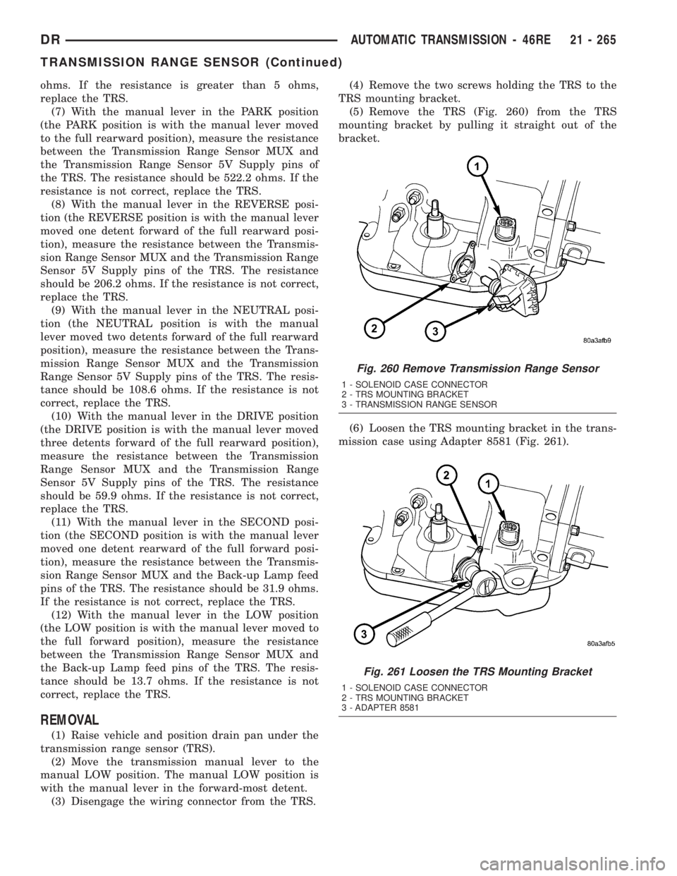
(5) Remove the TRS (Fig. 260) from the TRS
mounting bracket by pulling it straight out of the
bracket.
(6) Loosen the TRS mounting bracket in the trans-
mission case using Adapter 8581 (Fig. 261).
Fig. 260 Remove Transmission Range Sensor
1 - SOLENOID CASE CONNECTOR
2 - TRS MOUNTING BRACKET
3 - TRANSMISSION RANGE SENSOR
Fig. 261 Loosen the TRS Mounting Bracket
1 - SOLENOID CASE CONNECTOR
2 - TRS MOUNTING BRACKET
3 - ADAPTER 8581
DRAUTOMATIC TRANSMISSION - 46RE 21 - 265
TRANSMISSION RANGE SENSOR (Continued)
Page 2105 of 2895
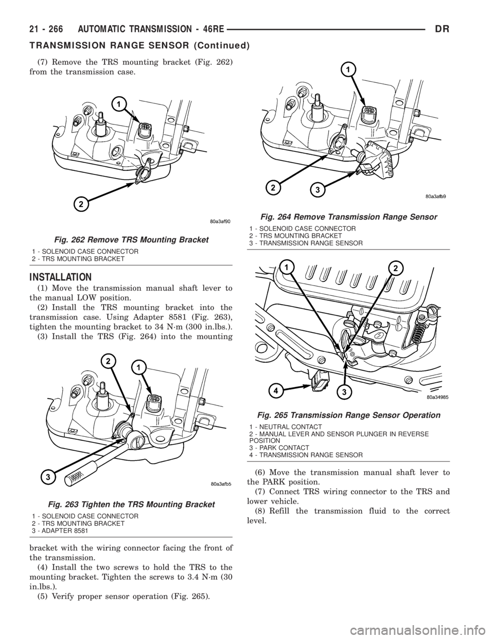
(7) Remove the TRS mounting bracket (Fig. 262)
from the transmission case.
INSTALLATION
(1) Move the transmission manual shaft lever to
the manual LOW position.
(2) Install the TRS mounting bracket into the
transmission case. Using Adapter 8581 (Fig. 263),
tighten the mounting bracket to 34 N´m (300 in.lbs.).
(3) Install the TRS (Fig. 264) into the mounting
bracket with the wiring connector facing the front of
the transmission.
(4) Install the two screws to hold the TRS to the
mounting bracket. Tighten the screws to 3.4 N´m (30
in.lbs.).
(5) Verify proper sensor operation (Fig. 265).(6) Move the transmission manual shaft lever to
the PARK position.
(7) Connect TRS wiring connector to the TRS and
lower vehicle.
(8) Refill the transmission fluid to the correct
level.
Fig. 262 Remove TRS Mounting Bracket
1 - SOLENOID CASE CONNECTOR
2 - TRS MOUNTING BRACKET
Fig. 263 Tighten the TRS Mounting Bracket
1 - SOLENOID CASE CONNECTOR
2 - TRS MOUNTING BRACKET
3 - ADAPTER 8581
Fig. 264 Remove Transmission Range Sensor
1 - SOLENOID CASE CONNECTOR
2 - TRS MOUNTING BRACKET
3 - TRANSMISSION RANGE SENSOR
Fig. 265 Transmission Range Sensor Operation
1 - NEUTRAL CONTACT
2 - MANUAL LEVER AND SENSOR PLUNGER IN REVERSE
POSITION
3 - PARK CONTACT
4 - TRANSMISSION RANGE SENSOR
21 - 266 AUTOMATIC TRANSMISSION - 46REDR
TRANSMISSION RANGE SENSOR (Continued)
Page 2106 of 2895
TRANSMISSION
TEMPERATURE SENSOR
DESCRIPTION
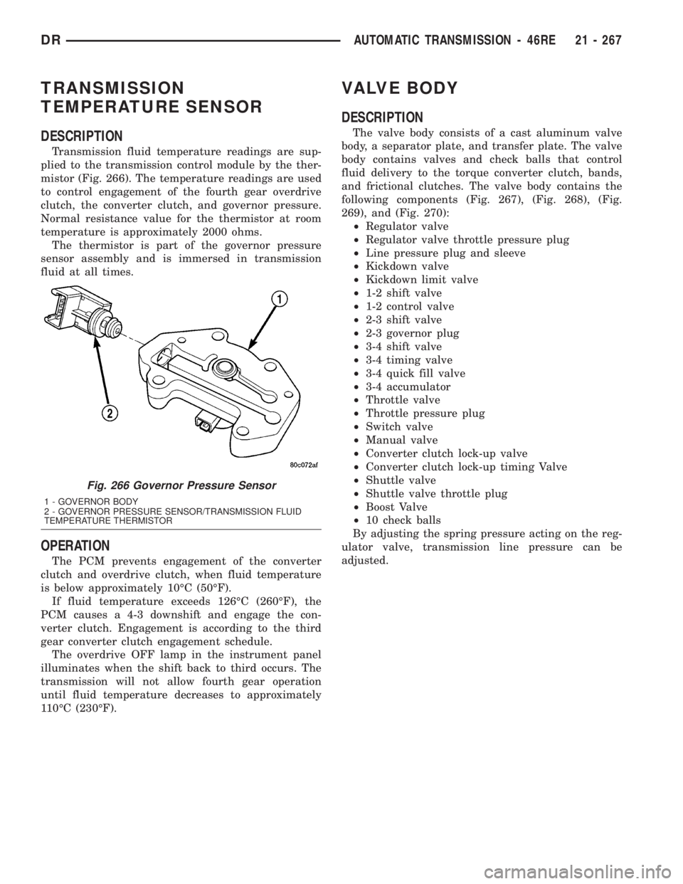
Transmission fluid temperature readings are sup-
plied to the transmission control module by the ther-
mistor (Fig. 266). The temperature readings are used
to control engagement of the fourth gear overdrive
clutch, the converter clutch, and governor pressure.
Normal resistance value for the thermistor at room
temperature is approximately 2000 ohms.
The thermistor is part of the governor pressure
sensor assembly and is immersed in transmission
fluid at all times.
OPERATION
The PCM prevents engagement of the converter
clutch and overdrive clutch, when fluid temperature
is below approximately 10ÉC (50ÉF).
If fluid temperature exceeds 126ÉC (260ÉF), the
PCM causes a 4-3 downshift and engage the con-
verter clutch. Engagement is according to the third
gear converter clutch engagement schedule.
The overdrive OFF lamp in the instrument panel
illuminates when the shift back to third occurs. The
transmission will not allow fourth gear operation
until fluid temperature decreases to approximately
110ÉC (230ÉF).
VALVE BODY
DESCRIPTION
The valve body consists of a cast aluminum valve
body, a separator plate, and transfer plate. The valve
body contains valves and check balls that control
fluid delivery to the torque converter clutch, bands,
and frictional clutches. The valve body contains the
following components (Fig. 267), (Fig. 268), (Fig.
269), and (Fig. 270):
²Regulator valve
²Regulator valve throttle pressure plug
²Line pressure plug and sleeve
²Kickdown valve
²Kickdown limit valve
²1-2 shift valve
²1-2 control valve
²2-3 shift valve
²2-3 governor plug
²3-4 shift valve
²3-4 timing valve
²3-4 quick fill valve
²3-4 accumulator
²Throttle valve
²Throttle pressure plug
²Switch valve
²Manual valve
²Converter clutch lock-up valve
²Converter clutch lock-up timing Valve
²Shuttle valve
²Shuttle valve throttle plug
²Boost Valve
²10 check balls
By adjusting the spring pressure acting on the reg-
ulator valve, transmission line pressure can be
adjusted.
Fig. 266 Governor Pressure Sensor
1 - GOVERNOR BODY
2 - GOVERNOR PRESSURE SENSOR/TRANSMISSION FLUID
TEMPERATURE THERMISTOR
DRAUTOMATIC TRANSMISSION - 46RE 21 - 267
Page 2107 of 2895
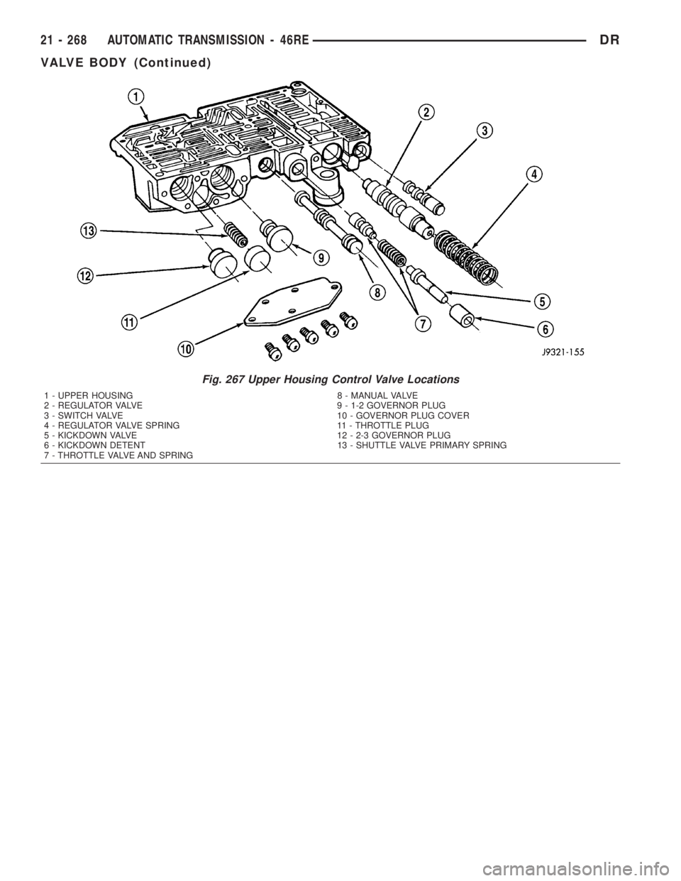
Fig. 267 Upper Housing Control Valve Locations
1 - UPPER HOUSING 8 - MANUAL VALVE
2 - REGULATOR VALVE 9 - 1-2 GOVERNOR PLUG
3 - SWITCH VALVE 10 - GOVERNOR PLUG COVER
4 - REGULATOR VALVE SPRING 11 - THROTTLE PLUG
5 - KICKDOWN VALVE 12 - 2-3 GOVERNOR PLUG
6 - KICKDOWN DETENT 13 - SHUTTLE VALVE PRIMARY SPRING
7 - THROTTLE VALVE AND SPRING
21 - 268 AUTOMATIC TRANSMISSION - 46REDR
VALVE BODY (Continued)
Page 2108 of 2895
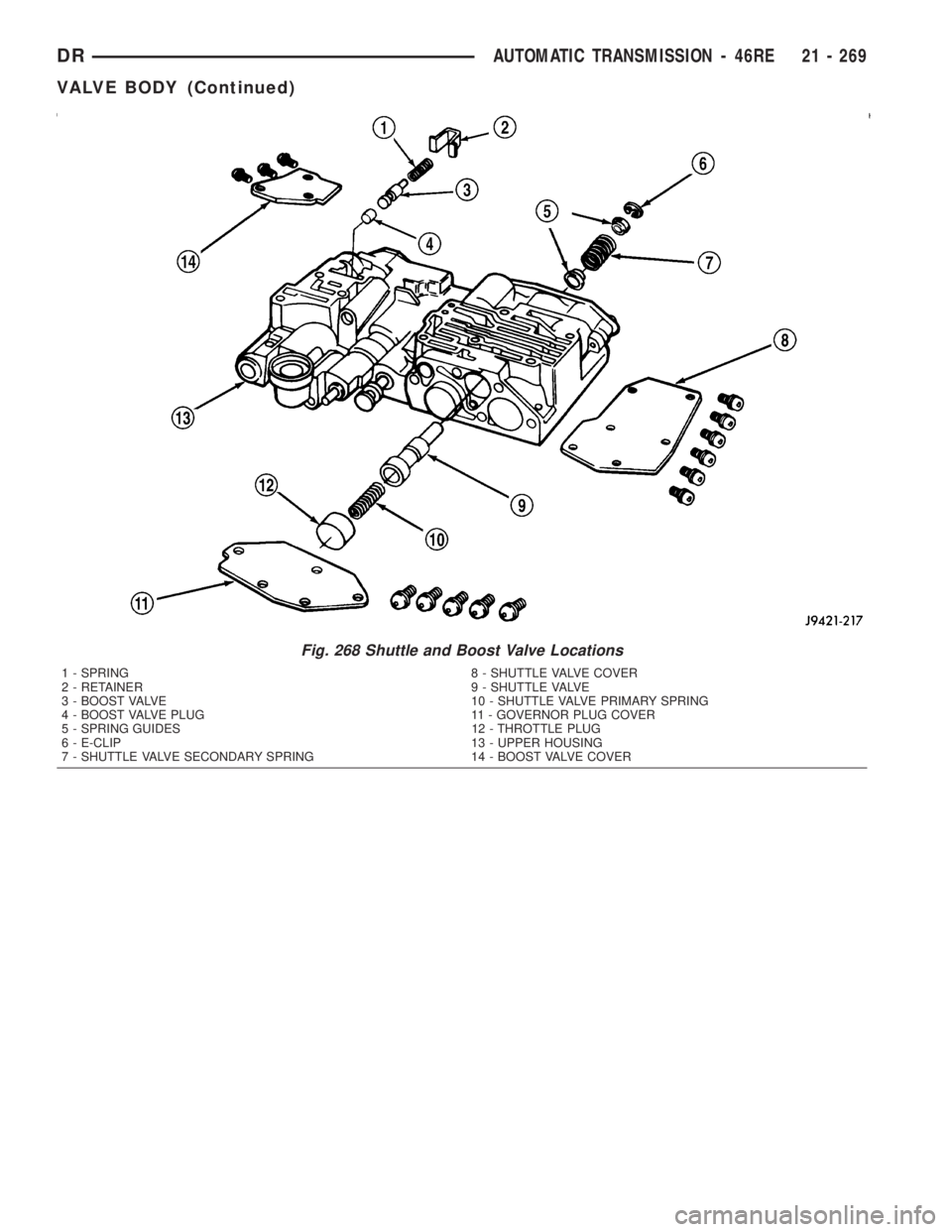
Fig. 268 Shuttle and Boost Valve Locations
1 - SPRING 8 - SHUTTLE VALVE COVER
2 - RETAINER 9 - SHUTTLE VALVE
3 - BOOST VALVE 10 - SHUTTLE VALVE PRIMARY SPRING
4 - BOOST VALVE PLUG 11 - GOVERNOR PLUG COVER
5 - SPRING GUIDES 12 - THROTTLE PLUG
6 - E-CLIP 13 - UPPER HOUSING
7 - SHUTTLE VALVE SECONDARY SPRING 14 - BOOST VALVE COVER
DRAUTOMATIC TRANSMISSION - 46RE 21 - 269
VALVE BODY (Continued)
Page 2109 of 2895
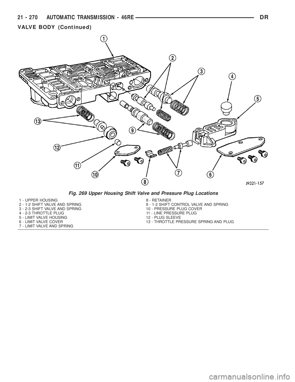
Fig. 269 Upper Housing Shift Valve and Pressure Plug Locations
1 - UPPER HOUSING 8 - RETAINER
2 - 1-2 SHIFT VALVE AND SPRING 9 - 1-2 SHIFT CONTROL VALVE AND SPRING
3 - 2-3 SHIFT VALVE AND SPRING 10 - PRESSURE PLUG COVER
4 - 2-3 THROTTLE PLUG 11 - LINE PRESSURE PLUG
5 - LIMIT VALVE HOUSING 12 - PLUG SLEEVE
6 - LIMIT VALVE COVER 13 - THROTTLE PRESSURE SPRING AND PLUG
7 - LIMIT VALVE AND SPRING
21 - 270 AUTOMATIC TRANSMISSION - 46REDR
VALVE BODY (Continued)
Page 2110 of 2895
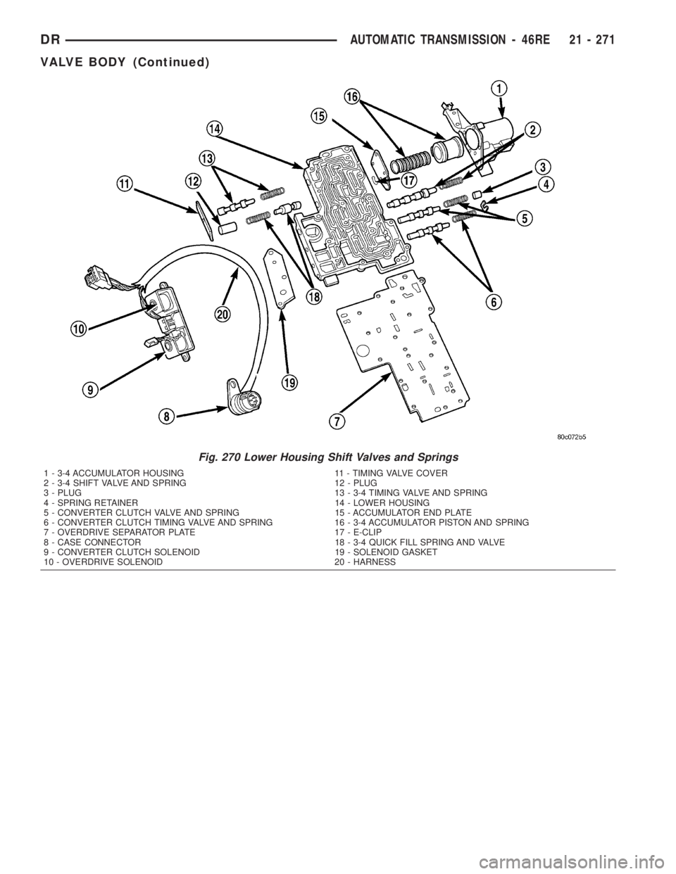
Fig. 270 Lower Housing Shift Valves and Springs
1 - 3-4 ACCUMULATOR HOUSING 11 - TIMING VALVE COVER
2 - 3-4 SHIFT VALVE AND SPRING 12 - PLUG
3 - PLUG 13 - 3-4 TIMING VALVE AND SPRING
4 - SPRING RETAINER 14 - LOWER HOUSING
5 - CONVERTER CLUTCH VALVE AND SPRING 15 - ACCUMULATOR END PLATE
6 - CONVERTER CLUTCH TIMING VALVE AND SPRING 16 - 3-4 ACCUMULATOR PISTON AND SPRING
7 - OVERDRIVE SEPARATOR PLATE 17 - E-CLIP
8 - CASE CONNECTOR 18 - 3-4 QUICK FILL SPRING AND VALVE
9 - CONVERTER CLUTCH SOLENOID 19 - SOLENOID GASKET
10 - OVERDRIVE SOLENOID 20 - HARNESS
DRAUTOMATIC TRANSMISSION - 46RE 21 - 271
VALVE BODY (Continued)