DODGE RAM 2003 Service Repair Manual
Manufacturer: DODGE, Model Year: 2003, Model line: RAM, Model: DODGE RAM 2003Pages: 2895, PDF Size: 83.15 MB
Page 2141 of 2895
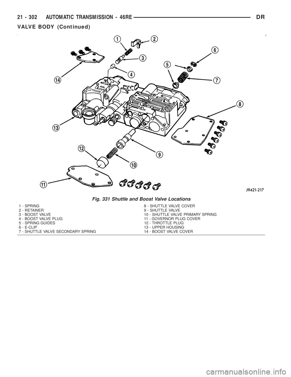
Fig. 331 Shuttle and Boost Valve Locations
1 - SPRING 8 - SHUTTLE VALVE COVER
2 - RETAINER 9 - SHUTTLE VALVE
3 - BOOST VALVE 10 - SHUTTLE VALVE PRIMARY SPRING
4 - BOOST VALVE PLUG 11 - GOVERNOR PLUG COVER
5 - SPRING GUIDES 12 - THROTTLE PLUG
6 - E-CLIP 13 - UPPER HOUSING
7 - SHUTTLE VALVE SECONDARY SPRING 14 - BOOST VALVE COVER
21 - 302 AUTOMATIC TRANSMISSION - 46REDR
VALVE BODY (Continued)
Page 2142 of 2895
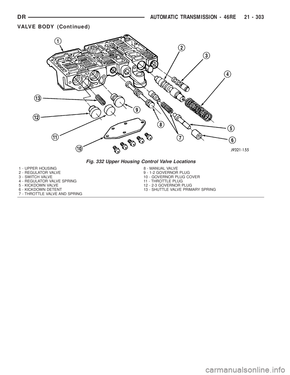
Fig. 332 Upper Housing Control Valve Locations
1 - UPPER HOUSING 8 - MANUAL VALVE
2 - REGULATOR VALVE 9 - 1-2 GOVERNOR PLUG
3 - SWITCH VALVE 10 - GOVERNOR PLUG COVER
4 - REGULATOR VALVE SPRING 11 - THROTTLE PLUG
5 - KICKDOWN VALVE 12 - 2-3 GOVERNOR PLUG
6 - KICKDOWN DETENT 13 - SHUTTLE VALVE PRIMARY SPRING
7 - THROTTLE VALVE AND SPRING
DRAUTOMATIC TRANSMISSION - 46RE 21 - 303
VALVE BODY (Continued)
Page 2143 of 2895
BOOST VALVE TUBE AND BRACE
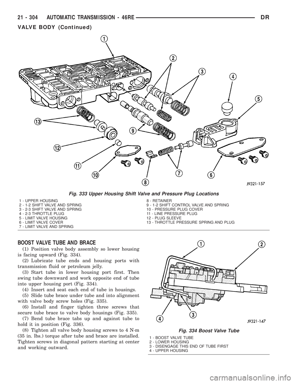
(1) Position valve body assembly so lower housing
is facing upward (Fig. 334).
(2) Lubricate tube ends and housing ports with
transmission fluid or petroleum jelly.
(3) Start tube in lower housing port first. Then
swing tube downward and work opposite end of tube
into upper housing port (Fig. 334).
(4) Insert and seat each end of tube in housings.
(5) Slide tube brace under tube and into alignment
with valve body screw holes (Fig. 335).
(6) Install and finger tighten three screws that
secure tube brace to valve body housings (Fig. 335).
(7) Bend tube brace tabs up and against tube to
hold it in position (Fig. 336).
(8) Tighten all valve body housing screws to 4 N´m
(35 in. lbs.) torque after tube and brace are installed.
Tighten screws in diagonal pattern starting at center
and working outward.
Fig. 333 Upper Housing Shift Valve and Pressure Plug Locations
1 - UPPER HOUSING 8 - RETAINER
2 - 1-2 SHIFT VALVE AND SPRING 9 - 1-2 SHIFT CONTROL VALVE AND SPRING
3 - 2-3 SHIFT VALVE AND SPRING 10 - PRESSURE PLUG COVER
4 - 2-3 THROTTLE PLUG 11 - LINE PRESSURE PLUG
5 - LIMIT VALVE HOUSING 12 - PLUG SLEEVE
6 - LIMIT VALVE COVER 13 - THROTTLE PRESSURE SPRING AND PLUG
7 - LIMIT VALVE AND SPRING
Fig. 334 Boost Valve Tube
1 - BOOST VALVE TUBE
2 - LOWER HOUSING
3 - DISENGAGE THIS END OF TUBE FIRST
4 - UPPER HOUSING
21 - 304 AUTOMATIC TRANSMISSION - 46REDR
VALVE BODY (Continued)
Page 2144 of 2895
3-4 ACCUMULATOR
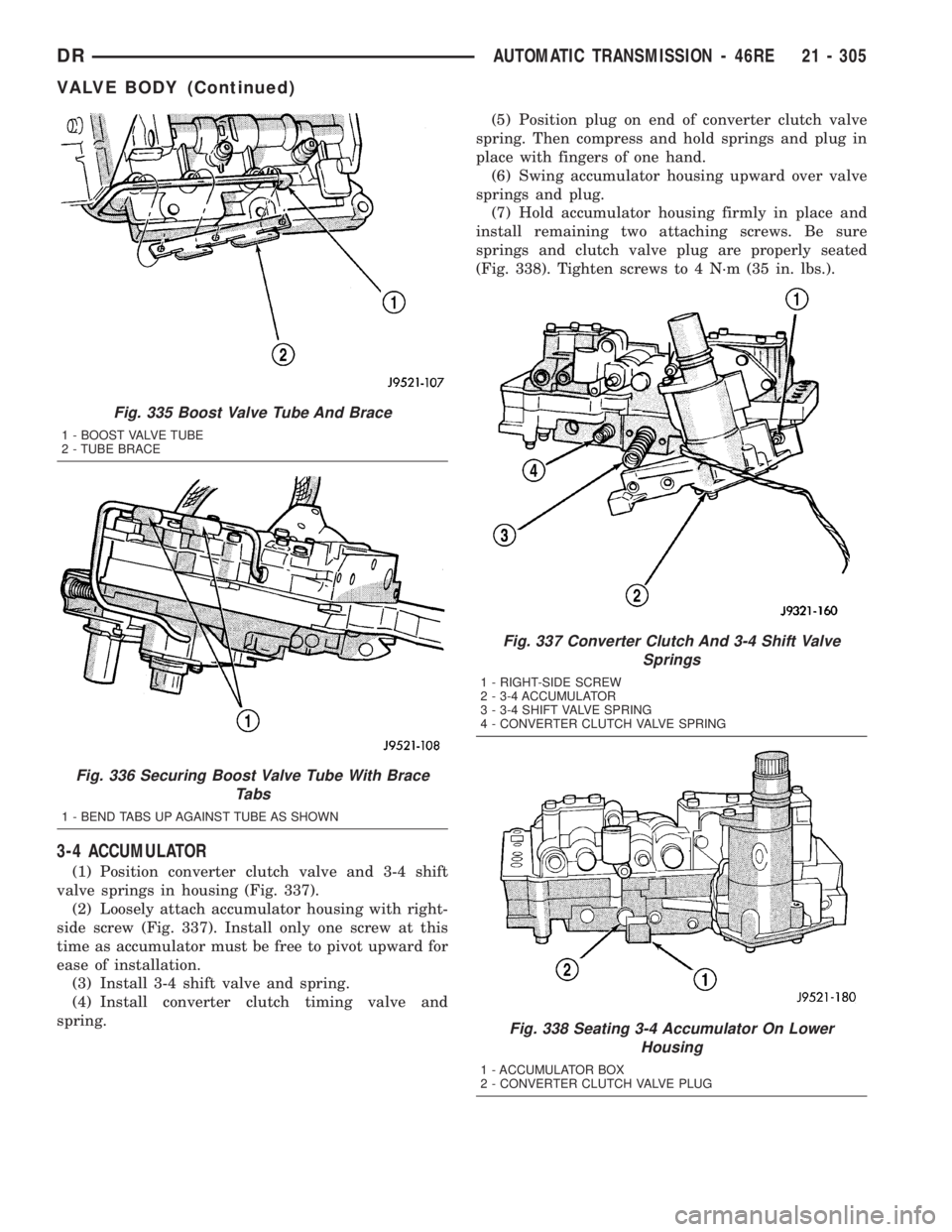
(1) Position converter clutch valve and 3-4 shift
valve springs in housing (Fig. 337).
(2) Loosely attach accumulator housing with right-
side screw (Fig. 337). Install only one screw at this
time as accumulator must be free to pivot upward for
ease of installation.
(3) Install 3-4 shift valve and spring.
(4) Install converter clutch timing valve and
spring.(5) Position plug on end of converter clutch valve
spring. Then compress and hold springs and plug in
place with fingers of one hand.
(6) Swing accumulator housing upward over valve
springs and plug.
(7) Hold accumulator housing firmly in place and
install remaining two attaching screws. Be sure
springs and clutch valve plug are properly seated
(Fig. 338). Tighten screws to 4 N´m (35 in. lbs.).
Fig. 335 Boost Valve Tube And Brace
1 - BOOST VALVE TUBE
2 - TUBE BRACE
Fig. 336 Securing Boost Valve Tube With Brace
Tabs
1 - BEND TABS UP AGAINST TUBE AS SHOWN
Fig. 337 Converter Clutch And 3-4 Shift Valve
Springs
1 - RIGHT-SIDE SCREW
2 - 3-4 ACCUMULATOR
3 - 3-4 SHIFT VALVE SPRING
4 - CONVERTER CLUTCH VALVE SPRING
Fig. 338 Seating 3-4 Accumulator On Lower
Housing
1 - ACCUMULATOR BOX
2 - CONVERTER CLUTCH VALVE PLUG
DRAUTOMATIC TRANSMISSION - 46RE 21 - 305
VALVE BODY (Continued)
Page 2145 of 2895
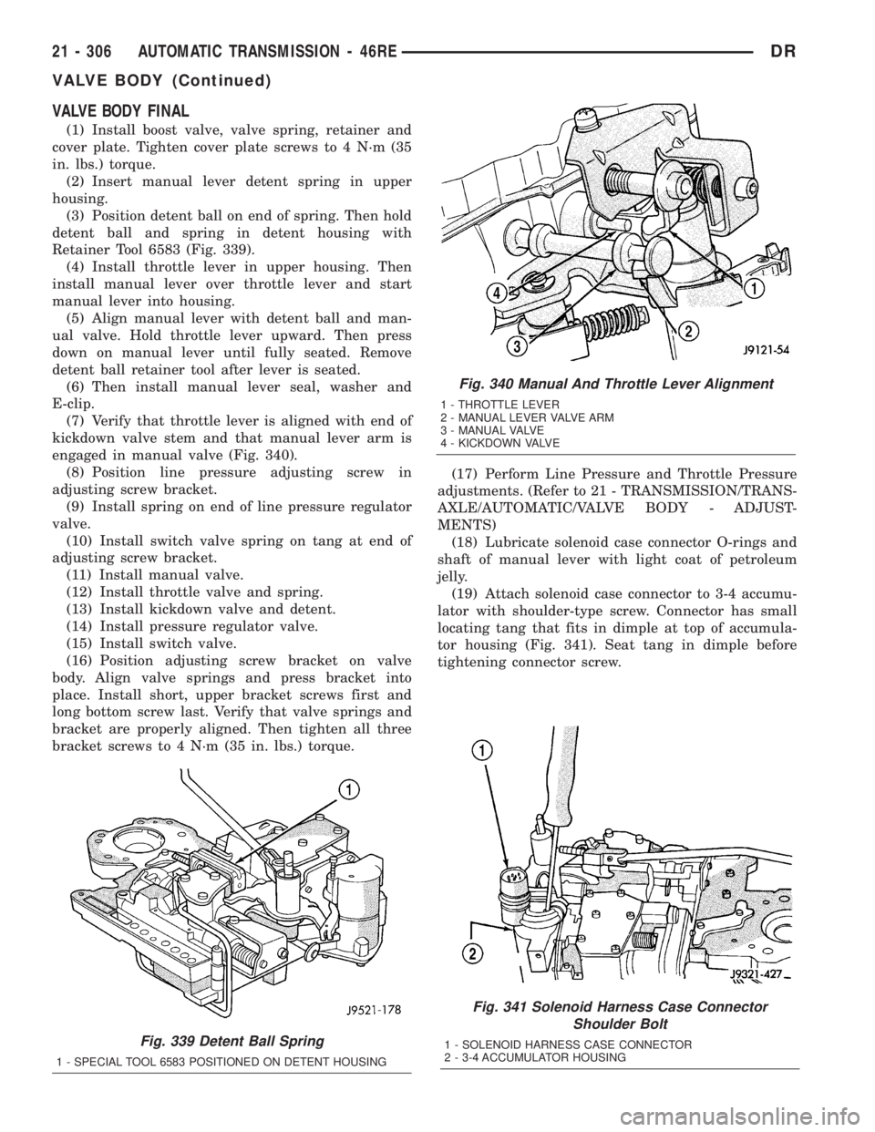
VALVE BODY FINAL
(1) Install boost valve, valve spring, retainer and
cover plate. Tighten cover plate screws to 4 N´m (35
in. lbs.) torque.
(2) Insert manual lever detent spring in upper
housing.
(3) Position detent ball on end of spring. Then hold
detent ball and spring in detent housing with
Retainer Tool 6583 (Fig. 339).
(4) Install throttle lever in upper housing. Then
install manual lever over throttle lever and start
manual lever into housing.
(5) Align manual lever with detent ball and man-
ual valve. Hold throttle lever upward. Then press
down on manual lever until fully seated. Remove
detent ball retainer tool after lever is seated.
(6) Then install manual lever seal, washer and
E-clip.
(7) Verify that throttle lever is aligned with end of
kickdown valve stem and that manual lever arm is
engaged in manual valve (Fig. 340).
(8) Position line pressure adjusting screw in
adjusting screw bracket.
(9) Install spring on end of line pressure regulator
valve.
(10) Install switch valve spring on tang at end of
adjusting screw bracket.
(11) Install manual valve.
(12) Install throttle valve and spring.
(13) Install kickdown valve and detent.
(14) Install pressure regulator valve.
(15) Install switch valve.
(16) Position adjusting screw bracket on valve
body. Align valve springs and press bracket into
place. Install short, upper bracket screws first and
long bottom screw last. Verify that valve springs and
bracket are properly aligned. Then tighten all three
bracket screws to 4 N´m (35 in. lbs.) torque.(17) Perform Line Pressure and Throttle Pressure
adjustments. (Refer to 21 - TRANSMISSION/TRANS-
AXLE/AUTOMATIC/VALVE BODY - ADJUST-
MENTS)
(18) Lubricate solenoid case connector O-rings and
shaft of manual lever with light coat of petroleum
jelly.
(19) Attach solenoid case connector to 3-4 accumu-
lator with shoulder-type screw. Connector has small
locating tang that fits in dimple at top of accumula-
tor housing (Fig. 341). Seat tang in dimple before
tightening connector screw.
Fig. 339 Detent Ball Spring
1 - SPECIAL TOOL 6583 POSITIONED ON DETENT HOUSING
Fig. 340 Manual And Throttle Lever Alignment
1 - THROTTLE LEVER
2 - MANUAL LEVER VALVE ARM
3 - MANUAL VALVE
4 - KICKDOWN VALVE
Fig. 341 Solenoid Harness Case Connector
Shoulder Bolt
1 - SOLENOID HARNESS CASE CONNECTOR
2 - 3-4 ACCUMULATOR HOUSING
21 - 306 AUTOMATIC TRANSMISSION - 46REDR
VALVE BODY (Continued)
Page 2146 of 2895
(20) Install solenoid assembly and gasket. Tighten
solenoid attaching screws to 8 N´m (72 in. lbs.)
torque.
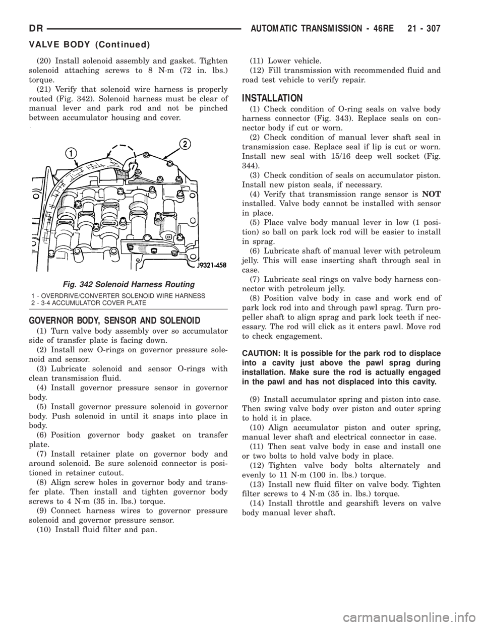
(21) Verify that solenoid wire harness is properly
routed (Fig. 342). Solenoid harness must be clear of
manual lever and park rod and not be pinched
between accumulator housing and cover.
GOVERNOR BODY, SENSOR AND SOLENOID
(1) Turn valve body assembly over so accumulator
side of transfer plate is facing down.
(2) Install new O-rings on governor pressure sole-
noid and sensor.
(3) Lubricate solenoid and sensor O-rings with
clean transmission fluid.
(4) Install governor pressure sensor in governor
body.
(5) Install governor pressure solenoid in governor
body. Push solenoid in until it snaps into place in
body.
(6) Position governor body gasket on transfer
plate.
(7) Install retainer plate on governor body and
around solenoid. Be sure solenoid connector is posi-
tioned in retainer cutout.
(8) Align screw holes in governor body and trans-
fer plate. Then install and tighten governor body
screws to 4 N´m (35 in. lbs.) torque.
(9) Connect harness wires to governor pressure
solenoid and governor pressure sensor.
(10) Install fluid filter and pan.(11) Lower vehicle.
(12) Fill transmission with recommended fluid and
road test vehicle to verify repair.
INSTALLATION
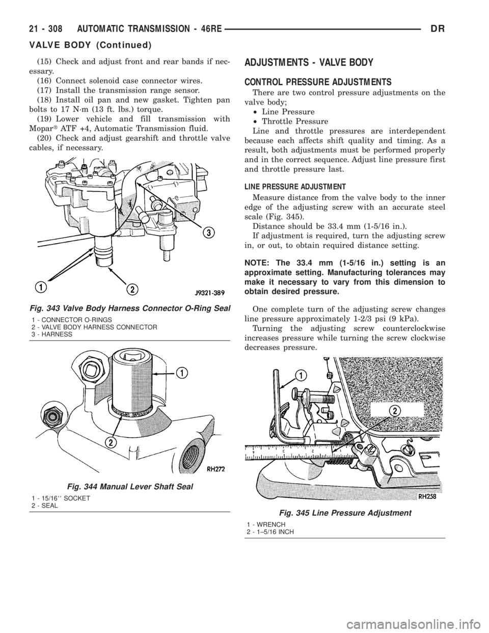
(1) Check condition of O-ring seals on valve body
harness connector (Fig. 343). Replace seals on con-
nector body if cut or worn.
(2) Check condition of manual lever shaft seal in
transmission case. Replace seal if lip is cut or worn.
Install new seal with 15/16 deep well socket (Fig.
344).
(3) Check condition of seals on accumulator piston.
Install new piston seals, if necessary.
(4) Verify that transmission range sensor isNOT
installed. Valve body cannot be installed with sensor
in place.
(5) Place valve body manual lever in low (1 posi-
tion) so ball on park lock rod will be easier to install
in sprag.
(6) Lubricate shaft of manual lever with petroleum
jelly. This will ease inserting shaft through seal in
case.
(7) Lubricate seal rings on valve body harness con-
nector with petroleum jelly.
(8) Position valve body in case and work end of
park lock rod into and through pawl sprag. Turn pro-
peller shaft to align sprag and park lock teeth if nec-
essary. The rod will click as it enters pawl. Move rod
to check engagement.
CAUTION: It is possible for the park rod to displace
into a cavity just above the pawl sprag during
installation. Make sure the rod is actually engaged
in the pawl and has not displaced into this cavity.
(9) Install accumulator spring and piston into case.
Then swing valve body over piston and outer spring
to hold it in place.
(10) Align accumulator piston and outer spring,
manual lever shaft and electrical connector in case.
(11) Then seat valve body in case and install one
or two bolts to hold valve body in place.
(12) Tighten valve body bolts alternately and
evenly to 11 N´m (100 in. lbs.) torque.
(13) Install new fluid filter on valve body. Tighten
filter screws to 4 N´m (35 in. lbs.) torque.
(14) Install throttle and gearshift levers on valve
body manual lever shaft.
Fig. 342 Solenoid Harness Routing
1 - OVERDRIVE/CONVERTER SOLENOID WIRE HARNESS
2 - 3-4 ACCUMULATOR COVER PLATE
DRAUTOMATIC TRANSMISSION - 46RE 21 - 307
VALVE BODY (Continued)
Page 2147 of 2895
(15) Check and adjust front and rear bands if nec-
essary.
(16) Connect solenoid case connector wires.
(17) Install the transmission range sensor.
(18) Install oil pan and new gasket. Tighten pan
bolts to 17 N´m (13 ft. lbs.) torque.
(19) Lower vehicle and fill transmission with
MopartATF +4, Automatic Transmission fluid.
(20) Check and adjust gearshift and throttle valve
cables, if necessary.ADJUSTMENTS - VALVE BODY
CONTROL PRESSURE ADJUSTMENTS
There are two control pressure adjustments on the
valve body;
²Line Pressure
²Throttle Pressure
Line and throttle pressures are interdependent
because each affects shift quality and timing. As a
result, both adjustments must be performed properly
and in the correct sequence. Adjust line pressure first
and throttle pressure last.
LINE PRESSURE ADJUSTMENT
Measure distance from the valve body to the inner
edge of the adjusting screw with an accurate steel
scale (Fig. 345).
Distance should be 33.4 mm (1-5/16 in.).
If adjustment is required, turn the adjusting screw
in, or out, to obtain required distance setting.
NOTE: The 33.4 mm (1-5/16 in.) setting is an
approximate setting. Manufacturing tolerances may
make it necessary to vary from this dimension to
obtain desired pressure.
One complete turn of the adjusting screw changes
line pressure approximately 1-2/3 psi (9 kPa).
Turning the adjusting screw counterclockwise
increases pressure while turning the screw clockwise
decreases pressure.
Fig. 343 Valve Body Harness Connector O-Ring Seal
1 - CONNECTOR O-RINGS
2 - VALVE BODY HARNESS CONNECTOR
3 - HARNESS
Fig. 344 Manual Lever Shaft Seal
1 - 15/1688SOCKET
2 - SEAL
Fig. 345 Line Pressure Adjustment
1 - WRENCH
2 - 1±5/16 INCH
21 - 308 AUTOMATIC TRANSMISSION - 46REDR
VALVE BODY (Continued)
Page 2148 of 2895
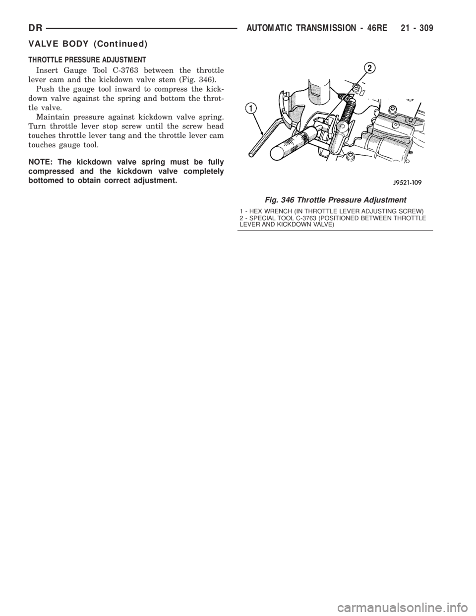
THROTTLE PRESSURE ADJUSTMENT
Insert Gauge Tool C-3763 between the throttle
lever cam and the kickdown valve stem (Fig. 346).
Push the gauge tool inward to compress the kick-
down valve against the spring and bottom the throt-
tle valve.
Maintain pressure against kickdown valve spring.
Turn throttle lever stop screw until the screw head
touches throttle lever tang and the throttle lever cam
touches gauge tool.
NOTE: The kickdown valve spring must be fully
compressed and the kickdown valve completely
bottomed to obtain correct adjustment.
Fig. 346 Throttle Pressure Adjustment
1 - HEX WRENCH (IN THROTTLE LEVER ADJUSTING SCREW)
2 - SPECIAL TOOL C-3763 (POSITIONED BETWEEN THROTTLE
LEVER AND KICKDOWN VALVE)
DRAUTOMATIC TRANSMISSION - 46RE 21 - 309
VALVE BODY (Continued)
Page 2149 of 2895
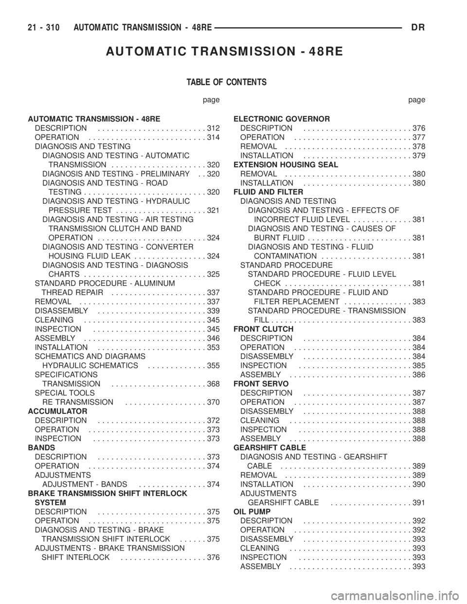
AUTOMATIC TRANSMISSION - 48RE
TABLE OF CONTENTS
page page
AUTOMATIC TRANSMISSION - 48RE
DESCRIPTION........................312
OPERATION..........................314
DIAGNOSIS AND TESTING
DIAGNOSIS AND TESTING - AUTOMATIC
TRANSMISSION.....................320
DIAGNOSIS AND TESTING - PRELIMINARY. . 320
DIAGNOSIS AND TESTING - ROAD
TESTING...........................320
DIAGNOSIS AND TESTING - HYDRAULIC
PRESSURE TEST....................321
DIAGNOSIS AND TESTING - AIR TESTING
TRANSMISSION CLUTCH AND BAND
OPERATION........................324
DIAGNOSIS AND TESTING - CONVERTER
HOUSING FLUID LEAK................324
DIAGNOSIS AND TESTING - DIAGNOSIS
CHARTS...........................325
STANDARD PROCEDURE - ALUMINUM
THREAD REPAIR.....................337
REMOVAL............................337
DISASSEMBLY........................339
CLEANING...........................345
INSPECTION.........................345
ASSEMBLY...........................346
INSTALLATION........................353
SCHEMATICS AND DIAGRAMS
HYDRAULIC SCHEMATICS.............355
SPECIFICATIONS
TRANSMISSION.....................368
SPECIAL TOOLS
RE TRANSMISSION..................370
ACCUMULATOR
DESCRIPTION........................372
OPERATION..........................373
INSPECTION.........................373
BANDS
DESCRIPTION........................373
OPERATION..........................374
ADJUSTMENTS
ADJUSTMENT - BANDS...............374
BRAKE TRANSMISSION SHIFT INTERLOCK
SYSTEM
DESCRIPTION........................375
OPERATION..........................375
DIAGNOSIS AND TESTING - BRAKE
TRANSMISSION SHIFT INTERLOCK......375
ADJUSTMENTS - BRAKE TRANSMISSION
SHIFT INTERLOCK...................376ELECTRONIC GOVERNOR
DESCRIPTION........................376
OPERATION..........................377
REMOVAL............................378
INSTALLATION........................379
EXTENSION HOUSING SEAL
REMOVAL............................380
INSTALLATION........................380
FLUID AND FILTER
DIAGNOSIS AND TESTING
DIAGNOSIS AND TESTING - EFFECTS OF
INCORRECT FLUID LEVEL.............381
DIAGNOSIS AND TESTING - CAUSES OF
BURNT FLUID.......................381
DIAGNOSIS AND TESTING - FLUID
CONTAMINATION....................381
STANDARD PROCEDURE
STANDARD PROCEDURE - FLUID LEVEL
CHECK............................381
STANDARD PROCEDURE - FLUID AND
FILTER REPLACEMENT...............383
STANDARD PROCEDURE - TRANSMISSION
FILL...............................383
FRONT CLUTCH
DESCRIPTION........................384
OPERATION..........................384
DISASSEMBLY........................384
INSPECTION.........................385
ASSEMBLY...........................386
FRONT SERVO
DESCRIPTION........................387
OPERATION..........................387
DISASSEMBLY........................388
CLEANING...........................388
INSPECTION.........................388
ASSEMBLY...........................388
GEARSHIFT CABLE
DIAGNOSIS AND TESTING - GEARSHIFT
CABLE.............................389
REMOVAL............................389
INSTALLATION........................390
ADJUSTMENTS
GEARSHIFT CABLE..................391
OIL PUMP
DESCRIPTION........................392
OPERATION..........................392
DISASSEMBLY........................393
CLEANING...........................393
INSPECTION.........................393
ASSEMBLY...........................393
21 - 310 AUTOMATIC TRANSMISSION - 48REDR
Page 2150 of 2895
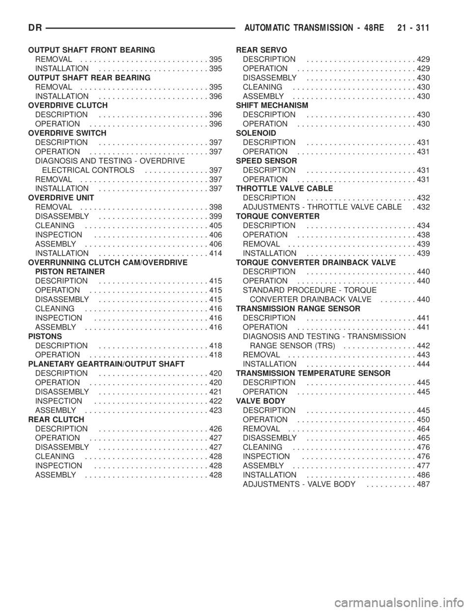
OUTPUT SHAFT FRONT BEARING
REMOVAL............................395
INSTALLATION........................395
OUTPUT SHAFT REAR BEARING
REMOVAL............................395
INSTALLATION........................396
OVERDRIVE CLUTCH
DESCRIPTION........................396
OPERATION..........................396
OVERDRIVE SWITCH
DESCRIPTION........................397
OPERATION..........................397
DIAGNOSIS AND TESTING - OVERDRIVE
ELECTRICAL CONTROLS..............397
REMOVAL............................397
INSTALLATION........................397
OVERDRIVE UNIT
REMOVAL............................398
DISASSEMBLY........................399
CLEANING...........................405
INSPECTION.........................406
ASSEMBLY...........................406
INSTALLATION........................414
OVERRUNNING CLUTCH CAM/OVERDRIVE
PISTON RETAINER
DESCRIPTION........................415
OPERATION..........................415
DISASSEMBLY........................415
CLEANING...........................416
INSPECTION.........................416
ASSEMBLY...........................416
PISTONS
DESCRIPTION........................418
OPERATION..........................418
PLANETARY GEARTRAIN/OUTPUT SHAFT
DESCRIPTION........................420
OPERATION..........................420
DISASSEMBLY........................421
INSPECTION.........................422
ASSEMBLY...........................423
REAR CLUTCH
DESCRIPTION........................426
OPERATION..........................427
DISASSEMBLY........................427
CLEANING...........................428
INSPECTION.........................428
ASSEMBLY...........................428REAR SERVO
DESCRIPTION........................429
OPERATION..........................429
DISASSEMBLY........................430
CLEANING...........................430
ASSEMBLY...........................430
SHIFT MECHANISM
DESCRIPTION........................430
OPERATION..........................430
SOLENOID
DESCRIPTION........................431
OPERATION..........................431
SPEED SENSOR
DESCRIPTION........................431
OPERATION..........................431
THROTTLE VALVE CABLE
DESCRIPTION........................432
ADJUSTMENTS - THROTTLE VALVE CABLE . 432
TORQUE CONVERTER
DESCRIPTION........................434
OPERATION..........................438
REMOVAL............................439
INSTALLATION........................439
TORQUE CONVERTER DRAINBACK VALVE
DESCRIPTION........................440
OPERATION..........................440
STANDARD PROCEDURE - TORQUE
CONVERTER DRAINBACK VALVE........440
TRANSMISSION RANGE SENSOR
DESCRIPTION........................441
OPERATION..........................441
DIAGNOSIS AND TESTING - TRANSMISSION
RANGE SENSOR (TRS)................442
REMOVAL............................443
INSTALLATION........................444
TRANSMISSION TEMPERATURE SENSOR
DESCRIPTION........................445
OPERATION..........................445
VALVE BODY
DESCRIPTION........................445
OPERATION..........................450
REMOVAL............................464
DISASSEMBLY........................465
CLEANING...........................476
INSPECTION.........................476
ASSEMBLY...........................477
INSTALLATION........................486
ADJUSTMENTS - VALVE BODY...........487
DRAUTOMATIC TRANSMISSION - 48RE 21 - 311