DODGE RAM 2003 Service Repair Manual
Manufacturer: DODGE, Model Year: 2003, Model line: RAM, Model: DODGE RAM 2003Pages: 2895, PDF Size: 83.15 MB
Page 2121 of 2895
THROTTLE VALVE
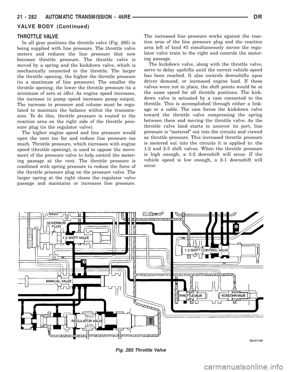
In all gear positions the throttle valve (Fig. 285) is
being supplied with line pressure. The throttle valve
meters and reduces the line pressure that now
becomes throttle pressure. The throttle valve is
moved by a spring and the kickdown valve, which is
mechanically connected to the throttle. The larger
the throttle opening, the higher the throttle pressure
(to a maximum of line pressure). The smaller the
throttle opening, the lower the throttle pressure (to a
minimum of zero at idle). As engine speed increases,
the increase in pump speed increases pump output.
The increase in pressure and volume must be regu-
lated to maintain the balance within the transmis-
sion. To do this, throttle pressure is routed to the
reaction area on the right side of the throttle pres-
sure plug (in the regulator valve).
The higher engine speed and line pressure would
open the vent too far and reduce line pressure too
much. Throttle pressure, which increases with engine
speed (throttle opening), is used to oppose the move-
ment of the pressure valve to help control the meter-
ing passage at the vent. The throttle pressure is
combined with spring pressure to reduce the force of
the throttle pressure plug on the pressure valve. The
larger spring at the right closes the regulator valve
passage and maintains or increases line pressure.The increased line pressure works against the reac-
tion area of the line pressure plug and the reaction
area left of land #3 simultaneously moves the regu-
lator valve train to the right and controls the meter-
ing passage.
The kickdown valve, along with the throttle valve,
serve to delay upshifts until the correct vehicle speed
has been reached. It also controls downshifts upon
driver demand, or increased engine load. If these
valves were not in place, the shift points would be at
the same speed for all throttle positions. The kick-
down valve is actuated by a cam connected to the
throttle. This is accomplished through either a link-
age or a cable. The cam forces the kickdown valve
toward the throttle valve compressing the spring
between them and moving the throttle valve. As the
throttle valve land starts to uncover its port, line
pressure is ªmeteredº out into the circuits and viewed
as throttle pressure. This increased throttle pressure
is metered out into the circuits it is applied to: the
1-2 and 2-3 shift valves. When the throttle pressure
is high enough, a 3-2 downshift will occur. If the
vehicle speed is low enough, a 2-1 downshift will
occur.
Fig. 285 Throttle Valve
21 - 282 AUTOMATIC TRANSMISSION - 46REDR
VALVE BODY (Continued)
Page 2122 of 2895
SWITCH VALVE
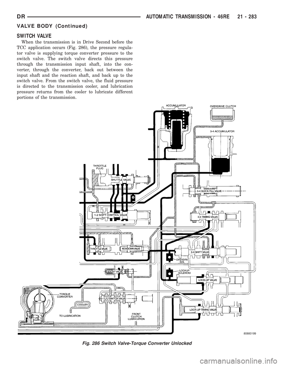
When the transmission is in Drive Second before the
TCC application occurs (Fig. 286), the pressure regula-
tor valve is supplying torque converter pressure to the
switch valve. The switch valve directs this pressure
through the transmission input shaft, into the con-
verter, through the converter, back out between the
input shaft and the reaction shaft, and back up to the
switch valve. From the switch valve, the fluid pressure
is directed to the transmission cooler, and lubrication
pressure returns from the cooler to lubricate different
portions of the transmission.
Fig. 286 Switch Valve-Torque Converter Unlocked
DRAUTOMATIC TRANSMISSION - 46RE 21 - 283
VALVE BODY (Continued)
Page 2123 of 2895
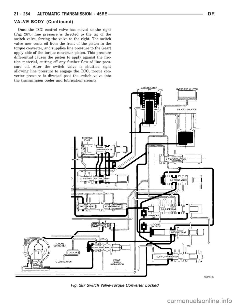
Once the TCC control valve has moved to the right
(Fig. 287), line pressure is directed to the tip of the
switch valve, forcing the valve to the right. The switch
valve now vents oil from the front of the piston in the
torque converter, and supplies line pressure to the (rear)
apply side of the torque converter piston. This pressure
differential causes the piston to apply against the fric-
tion material, cutting off any further flow of line pres-
sure oil. After the switch valve is shuttled right
allowing line pressure to engage the TCC, torque con-
verter pressure is directed past the switch valve into
the transmission cooler and lubrication circuits.
Fig. 287 Switch Valve-Torque Converter Locked
21 - 284 AUTOMATIC TRANSMISSION - 46REDR
VALVE BODY (Continued)
Page 2124 of 2895
MANUAL VALVE
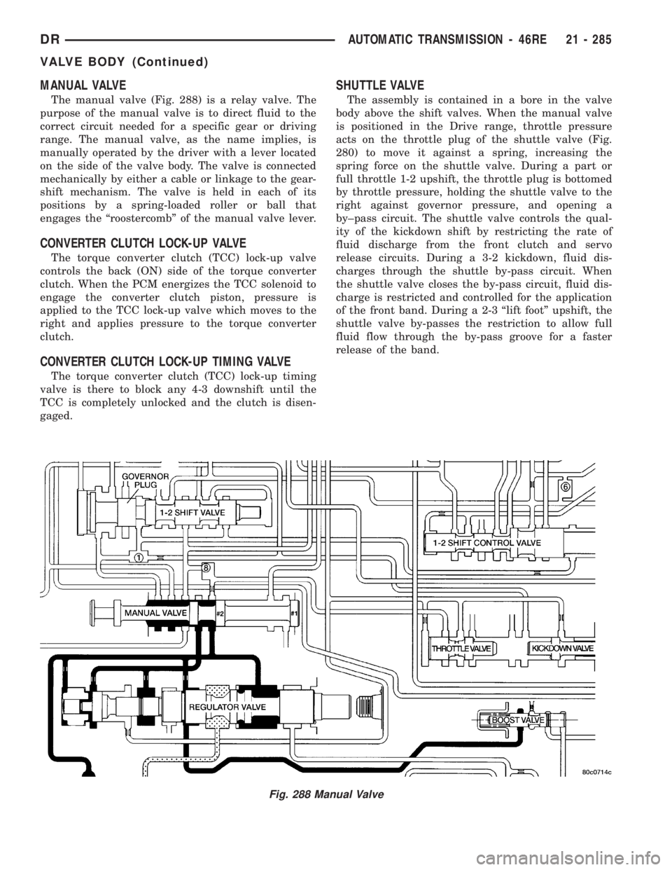
The manual valve (Fig. 288) is a relay valve. The
purpose of the manual valve is to direct fluid to the
correct circuit needed for a specific gear or driving
range. The manual valve, as the name implies, is
manually operated by the driver with a lever located
on the side of the valve body. The valve is connected
mechanically by either a cable or linkage to the gear-
shift mechanism. The valve is held in each of its
positions by a spring-loaded roller or ball that
engages the ªroostercombº of the manual valve lever.
CONVERTER CLUTCH LOCK-UP VALVE
The torque converter clutch (TCC) lock-up valve
controls the back (ON) side of the torque converter
clutch. When the PCM energizes the TCC solenoid to
engage the converter clutch piston, pressure is
applied to the TCC lock-up valve which moves to the
right and applies pressure to the torque converter
clutch.
CONVERTER CLUTCH LOCK-UP TIMING VALVE
The torque converter clutch (TCC) lock-up timing
valve is there to block any 4-3 downshift until the
TCC is completely unlocked and the clutch is disen-
gaged.
SHUTTLE VALVE
The assembly is contained in a bore in the valve
body above the shift valves. When the manual valve
is positioned in the Drive range, throttle pressure
acts on the throttle plug of the shuttle valve (Fig.
280) to move it against a spring, increasing the
spring force on the shuttle valve. During a part or
full throttle 1-2 upshift, the throttle plug is bottomed
by throttle pressure, holding the shuttle valve to the
right against governor pressure, and opening a
by±pass circuit. The shuttle valve controls the qual-
ity of the kickdown shift by restricting the rate of
fluid discharge from the front clutch and servo
release circuits. During a 3-2 kickdown, fluid dis-
charges through the shuttle by-pass circuit. When
the shuttle valve closes the by-pass circuit, fluid dis-
charge is restricted and controlled for the application
of the front band. During a 2-3 ªlift footº upshift, the
shuttle valve by-passes the restriction to allow full
fluid flow through the by-pass groove for a faster
release of the band.
Fig. 288 Manual Valve
DRAUTOMATIC TRANSMISSION - 46RE 21 - 285
VALVE BODY (Continued)
Page 2125 of 2895
BOOST VALVE
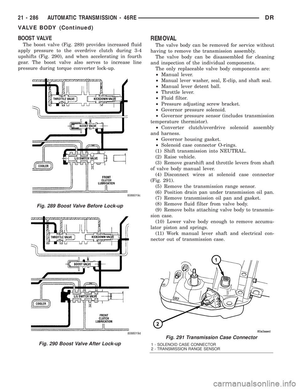
The boost valve (Fig. 289) provides increased fluid
apply pressure to the overdrive clutch during 3-4
upshifts (Fig. 290), and when accelerating in fourth
gear. The boost valve also serves to increase line
pressure during torque converter lock-up.
REMOVAL
The valve body can be removed for service without
having to remove the transmission assembly.
The valve body can be disassembled for cleaning
and inspection of the individual components.
The only replaceable valve body components are:
²Manual lever.
²
Manual lever washer, seal, E-clip, and shaft seal.
²Manual lever detent ball.
²Throttle lever.
²Fluid filter.
²Pressure adjusting screw bracket.
²Governor pressure solenoid.
²Governor pressure sensor (includes transmission
temperature thermistor).
²Converter clutch/overdrive solenoid assembly
and harness.
²Governor housing gasket.
²Solenoid case connector O-rings.
(1) Shift transmission into NEUTRAL.
(2) Raise vehicle.
(3) Remove gearshift and throttle levers from shaft
of valve body manual lever.
(4) Disconnect wires at solenoid case connector
(Fig. 291).
(5) Remove the transmission range sensor.
(6) Position drain pan under transmission oil pan.
(7) Remove transmission oil pan and gasket.
(8) Remove fluid filter from valve body.
(9) Remove bolts attaching valve body to transmis-
sion case.
(10) Lower valve body enough to remove accumu-
lator piston and springs.
(11) Work manual lever shaft and electrical con-
nector out of transmission case.
Fig. 291 Transmission Case Connector
1 - SOLENOID CASE CONNECTOR
2 - TRANSMISSION RANGE SENSOR
Fig. 289 Boost Valve Before Lock-up
Fig. 290 Boost Valve After Lock-up
21 - 286 AUTOMATIC TRANSMISSION - 46REDR
VALVE BODY (Continued)
Page 2126 of 2895
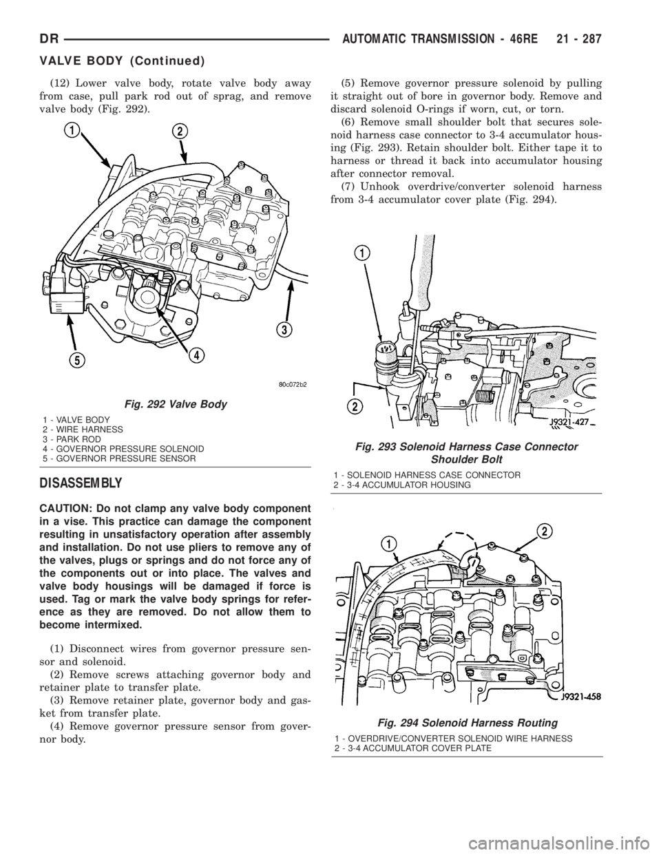
(12) Lower valve body, rotate valve body away
from case, pull park rod out of sprag, and remove
valve body (Fig. 292).
DISASSEMBLY
CAUTION: Do not clamp any valve body component
in a vise. This practice can damage the component
resulting in unsatisfactory operation after assembly
and installation. Do not use pliers to remove any of
the valves, plugs or springs and do not force any of
the components out or into place. The valves and
valve body housings will be damaged if force is
used. Tag or mark the valve body springs for refer-
ence as they are removed. Do not allow them to
become intermixed.
(1) Disconnect wires from governor pressure sen-
sor and solenoid.
(2) Remove screws attaching governor body and
retainer plate to transfer plate.
(3) Remove retainer plate, governor body and gas-
ket from transfer plate.
(4) Remove governor pressure sensor from gover-
nor body.(5) Remove governor pressure solenoid by pulling
it straight out of bore in governor body. Remove and
discard solenoid O-rings if worn, cut, or torn.
(6) Remove small shoulder bolt that secures sole-
noid harness case connector to 3-4 accumulator hous-
ing (Fig. 293). Retain shoulder bolt. Either tape it to
harness or thread it back into accumulator housing
after connector removal.
(7) Unhook overdrive/converter solenoid harness
from 3-4 accumulator cover plate (Fig. 294).
Fig. 293 Solenoid Harness Case Connector
Shoulder Bolt
1 - SOLENOID HARNESS CASE CONNECTOR
2 - 3-4 ACCUMULATOR HOUSING
Fig. 294 Solenoid Harness Routing
1 - OVERDRIVE/CONVERTER SOLENOID WIRE HARNESS
2 - 3-4 ACCUMULATOR COVER PLATE
Fig. 292 Valve Body
1 - VALVE BODY
2 - WIRE HARNESS
3 - PARK ROD
4 - GOVERNOR PRESSURE SOLENOID
5 - GOVERNOR PRESSURE SENSOR
DRAUTOMATIC TRANSMISSION - 46RE 21 - 287
VALVE BODY (Continued)
Page 2127 of 2895
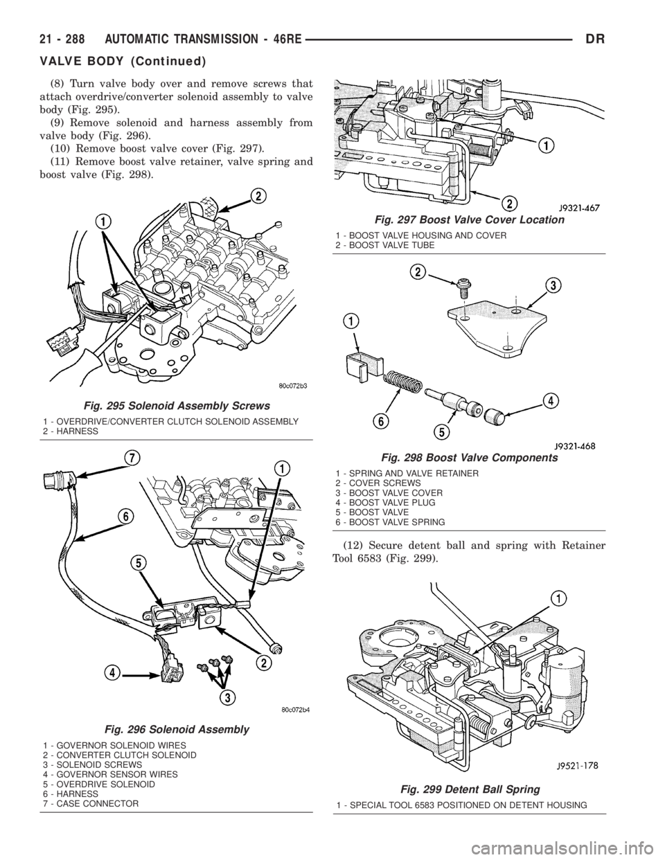
(8) Turn valve body over and remove screws that
attach overdrive/converter solenoid assembly to valve
body (Fig. 295).
(9) Remove solenoid and harness assembly from
valve body (Fig. 296).
(10) Remove boost valve cover (Fig. 297).
(11) Remove boost valve retainer, valve spring and
boost valve (Fig. 298).
(12) Secure detent ball and spring with Retainer
Tool 6583 (Fig. 299).
Fig. 299 Detent Ball Spring
1 - SPECIAL TOOL 6583 POSITIONED ON DETENT HOUSING
Fig. 295 Solenoid Assembly Screws
1 - OVERDRIVE/CONVERTER CLUTCH SOLENOID ASSEMBLY
2 - HARNESS
Fig. 296 Solenoid Assembly
1 - GOVERNOR SOLENOID WIRES
2 - CONVERTER CLUTCH SOLENOID
3 - SOLENOID SCREWS
4 - GOVERNOR SENSOR WIRES
5 - OVERDRIVE SOLENOID
6 - HARNESS
7 - CASE CONNECTOR
Fig. 297 Boost Valve Cover Location
1 - BOOST VALVE HOUSING AND COVER
2 - BOOST VALVE TUBE
Fig. 298 Boost Valve Components
1 - SPRING AND VALVE RETAINER
2 - COVER SCREWS
3 - BOOST VALVE COVER
4 - BOOST VALVE PLUG
5 - BOOST VALVE
6 - BOOST VALVE SPRING
21 - 288 AUTOMATIC TRANSMISSION - 46REDR
VALVE BODY (Continued)
Page 2128 of 2895
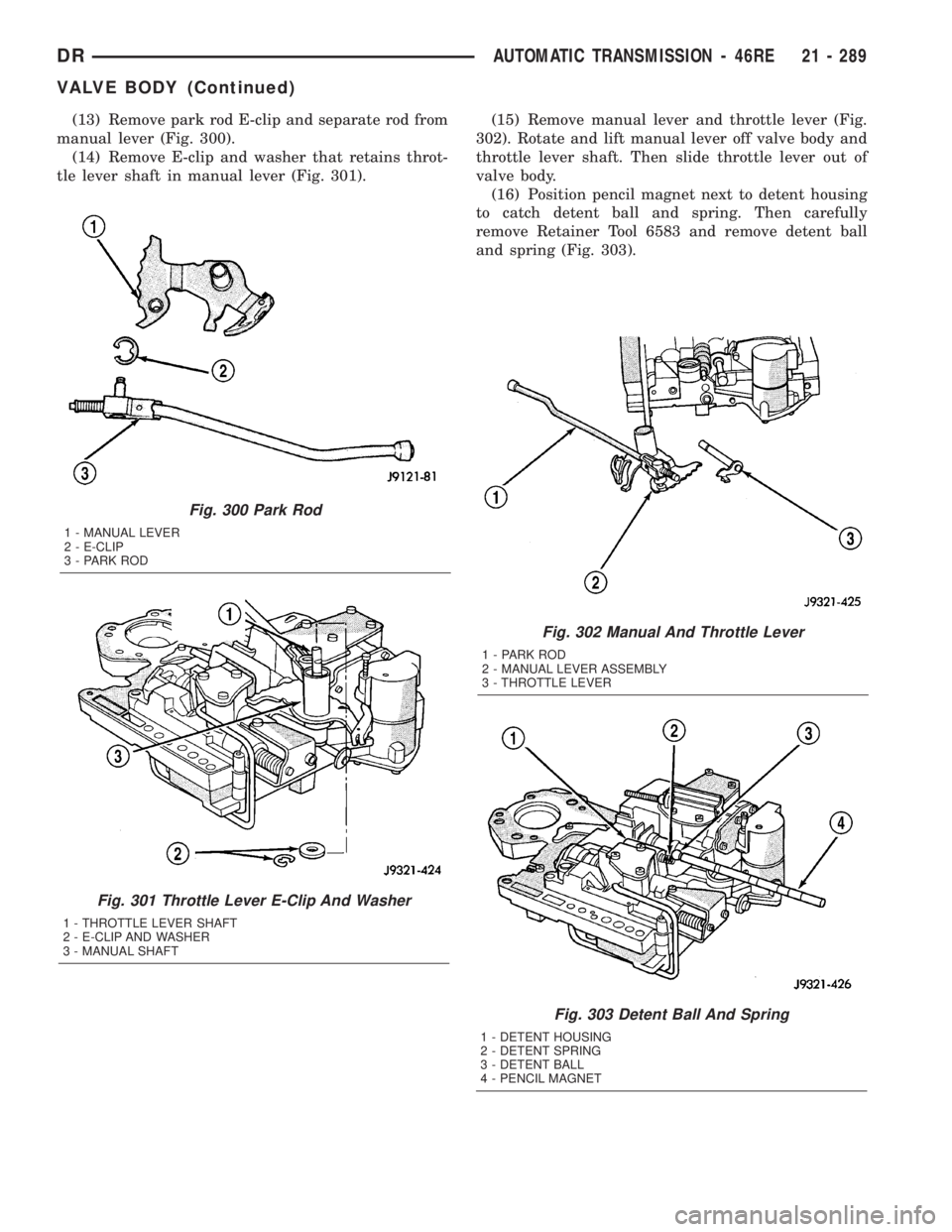
(13) Remove park rod E-clip and separate rod from
manual lever (Fig. 300).
(14) Remove E-clip and washer that retains throt-
tle lever shaft in manual lever (Fig. 301).(15) Remove manual lever and throttle lever (Fig.
302). Rotate and lift manual lever off valve body and
throttle lever shaft. Then slide throttle lever out of
valve body.
(16) Position pencil magnet next to detent housing
to catch detent ball and spring. Then carefully
remove Retainer Tool 6583 and remove detent ball
and spring (Fig. 303).
Fig. 300 Park Rod
1 - MANUAL LEVER
2 - E-CLIP
3 - PARK ROD
Fig. 301 Throttle Lever E-Clip And Washer
1 - THROTTLE LEVER SHAFT
2 - E-CLIP AND WASHER
3 - MANUAL SHAFT
Fig. 302 Manual And Throttle Lever
1 - PARK ROD
2 - MANUAL LEVER ASSEMBLY
3 - THROTTLE LEVER
Fig. 303 Detent Ball And Spring
1 - DETENT HOUSING
2 - DETENT SPRING
3 - DETENT BALL
4 - PENCIL MAGNET
DRAUTOMATIC TRANSMISSION - 46RE 21 - 289
VALVE BODY (Continued)
Page 2129 of 2895
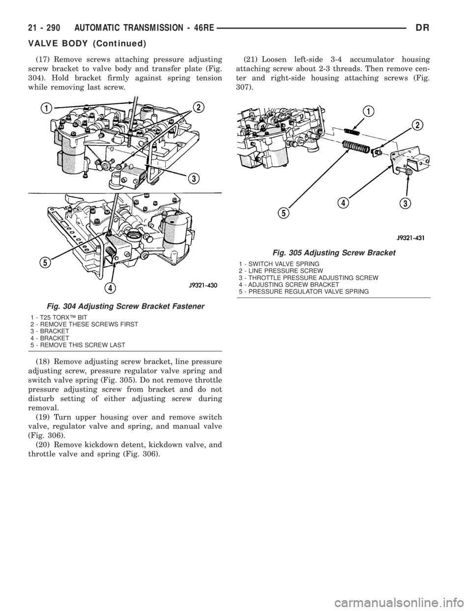
(17) Remove screws attaching pressure adjusting
screw bracket to valve body and transfer plate (Fig.
304). Hold bracket firmly against spring tension
while removing last screw.
(18) Remove adjusting screw bracket, line pressure
adjusting screw, pressure regulator valve spring and
switch valve spring (Fig. 305). Do not remove throttle
pressure adjusting screw from bracket and do not
disturb setting of either adjusting screw during
removal.
(19) Turn upper housing over and remove switch
valve, regulator valve and spring, and manual valve
(Fig. 306).
(20) Remove kickdown detent, kickdown valve, and
throttle valve and spring (Fig. 306).(21) Loosen left-side 3-4 accumulator housing
attaching screw about 2-3 threads. Then remove cen-
ter and right-side housing attaching screws (Fig.
307).
Fig. 305 Adjusting Screw Bracket
1 - SWITCH VALVE SPRING
2 - LINE PRESSURE SCREW
3 - THROTTLE PRESSURE ADJUSTING SCREW
4 - ADJUSTING SCREW BRACKET
5 - PRESSURE REGULATOR VALVE SPRING
Fig. 304 Adjusting Screw Bracket Fastener
1 - T25 TORXŸ BIT
2 - REMOVE THESE SCREWS FIRST
3 - BRACKET
4 - BRACKET
5 - REMOVE THIS SCREW LAST
21 - 290 AUTOMATIC TRANSMISSION - 46REDR
VALVE BODY (Continued)
Page 2130 of 2895
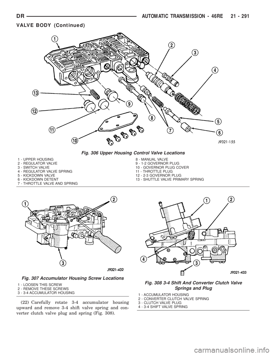
(22) Carefully rotate 3-4 accumulator housing
upward and remove 3-4 shift valve spring and con-
verter clutch valve plug and spring (Fig. 308).
Fig. 306 Upper Housing Control Valve Locations
1 - UPPER HOUSING 8 - MANUAL VALVE
2 - REGULATOR VALVE 9 - 1-2 GOVERNOR PLUG
3 - SWITCH VALVE 10 - GOVERNOR PLUG COVER
4 - REGULATOR VALVE SPRING 11 - THROTTLE PLUG
5 - KICKDOWN VALVE 12 - 2-3 GOVERNOR PLUG
6 - KICKDOWN DETENT 13 - SHUTTLE VALVE PRIMARY SPRING
7 - THROTTLE VALVE AND SPRING
Fig. 307 Accumulator Housing Screw Locations
1 - LOOSEN THIS SCREW
2 - REMOVE THESE SCREWS
3 - 3-4 ACCUMULATOR HOUSINGFig. 308 3-4 Shift And Converter Clutch Valve
Springs and Plug
1 - ACCUMULATOR HOUSING
2 - CONVERTER CLUTCH VALVE SPRING
3 - CLUTCH VALVE PLUG
4 - 3-4 SHIFT VALVE SPRING
DRAUTOMATIC TRANSMISSION - 46RE 21 - 291
VALVE BODY (Continued)