DODGE RAM SRT-10 2006 Service Repair Manual
Manufacturer: DODGE, Model Year: 2006, Model line: RAM SRT-10, Model: DODGE RAM SRT-10 2006Pages: 5267, PDF Size: 68.7 MB
Page 1421 of 5267
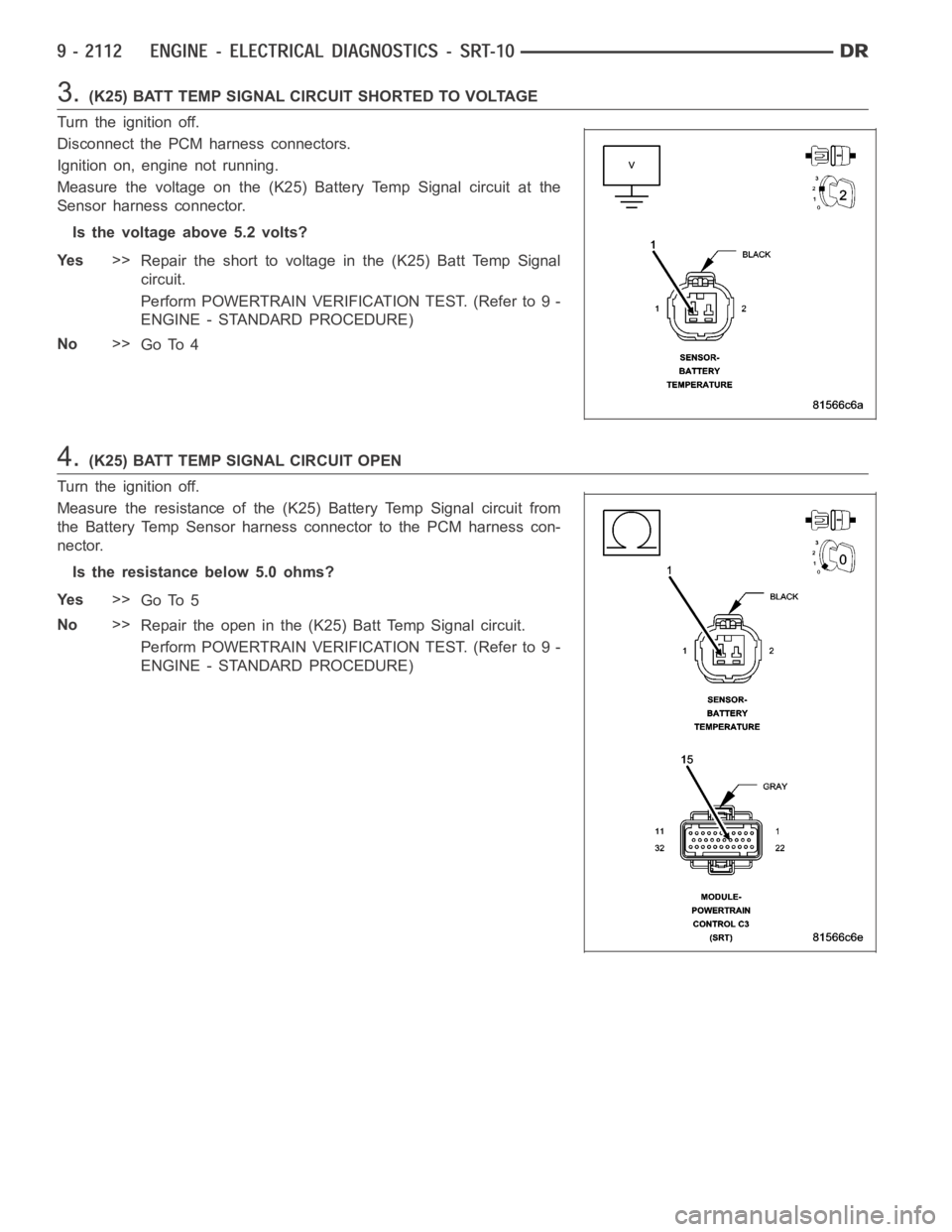
3.(K25) BATT TEMP SIGNAL CIRCUIT SHORTED TO VOLTAGE
Turn the ignition off.
Disconnect the PCM harness connectors.
Ignition on, engine not running.
Measure the voltage on the (K25) Battery Temp Signal circuit at the
Sensor harness connector.
Is the voltage above 5.2 volts?
Ye s>>
Repair the short to voltage in the (K25) Batt Temp Signal
circuit.
Perform POWERTRAIN VERIFICATION TEST. (Refer to 9 -
ENGINE - STANDARD PROCEDURE)
No>>
Go To 4
4.(K25) BATT TEMP SIGNAL CIRCUIT OPEN
Turn the ignition off.
Measure the resistance of the (K25) Battery Temp Signal circuit from
the Battery Temp Sensor harness connector to the PCM harness con-
nector.
Is the resistance below 5.0 ohms?
Ye s>>
Go To 5
No>>
Repair the open in the (K25) Batt Temp Signal circuit.
Perform POWERTRAIN VERIFICATION TEST. (Refer to 9 -
ENGINE - STANDARD PROCEDURE)
Page 1422 of 5267
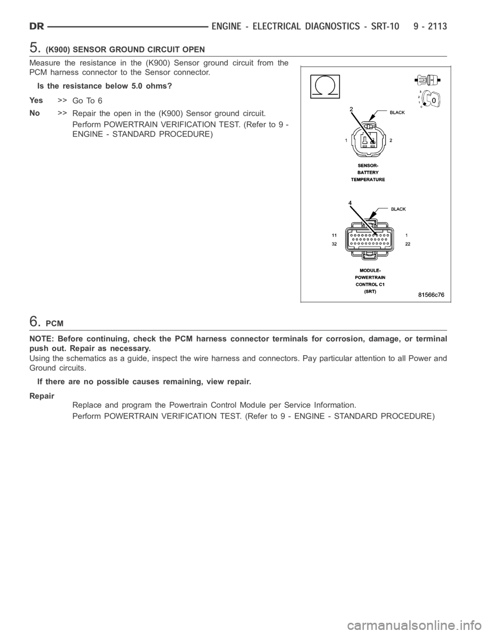
5.(K900) SENSOR GROUND CIRCUIT OPEN
Measure the resistance in the (K900) Sensor ground circuit from the
PCM harness connector to the Sensor connector.
Is the resistance below 5.0 ohms?
Ye s>>
Go To 6
No>>
Repair the open in the (K900) Sensor ground circuit.
Perform POWERTRAIN VERIFICATION TEST. (Refer to 9 -
ENGINE - STANDARD PROCEDURE)
6.PCM
NOTE: Before continuing, check the PCM harness connector terminals for corrosion, damage, or terminal
push out. Repair as necessary.
Using the schematics as a guide, inspect the wire harness and connectors. Pay particular attention to all Power and
Ground circuits.
If there are no possible causes remaining, view repair.
Repair
Replace and program the Powertrain Control Module per Service Information.
Perform POWERTRAIN VERIFICATION TEST. (Refer to 9 - ENGINE - STANDARD PROCEDURE)
Page 1423 of 5267

P1493-AMBIENT/BATTERY TEMPERATURE SENSOR VOLTAGE TOO LOW
For a complete wiring diagramRefer to Section 8W.
Page 1424 of 5267
When Monitored:
With the ignition on.
Set Condition:
The PCM senses the voltage from the Battery Temperature Sensor below 0.5 ofa volt for 3 seconds.
Possible Causes
BATTERY TEMP SENSOR VOLTAGE BELOW 0.5 OF A VOLT
BATTERY TEMPERATURE SENSOR
(K25) BATTERY TEMP SIGNAL CIRCUIT SHORTED TO GROUND
(K25) BATTERY TEMP SIGNAL CIRCUIT SHORTED TO THE (K900) SENSOR GROUND
PCM
Always perform the Pre-Diagnostic Troubleshooting procedure before proceeding. (Refer to 9 - ENGINE -
DIAGNOSIS AND TESTING)
1.BATTERY TEMP SENSOR VOLTAGE BELOW 0.5 OF A VOLT
Ignition on, engine not running.
Record all DTCs and the related Freeze Frame data.
With scan tool, monitor the Ambient/Battery Temperature Sensor voltage.
Is the voltage below 0.5 of a volt?
Ye s>>
Go To 2
No>>
Refer to the INTERMITTENT CONDITIONSymptom (Diagnostic Procedure).
Perform POWERTRAIN VERIFICATION TEST. (Refer to 9 - ENGINE - STANDARD PROCEDURE)
2.BATTERY TEMPERATURE SENSOR
Ignition on, engine not running.
With the scan tool in sensors, read the Battery Temp Sensor voltage.
Disconnect the Battery Temp Sensor harness connector.
Did the Battery Temperature Sensor voltage change from below 1.0 volt to above 4.5 volts?
Ye s>>
Replace the Battery Temperature Sensor.
Perform POWERTRAIN VERIFICATION TEST. (Refer to 9 - ENGINE - STANDARD PROCEDURE)
No>>
Go To 3
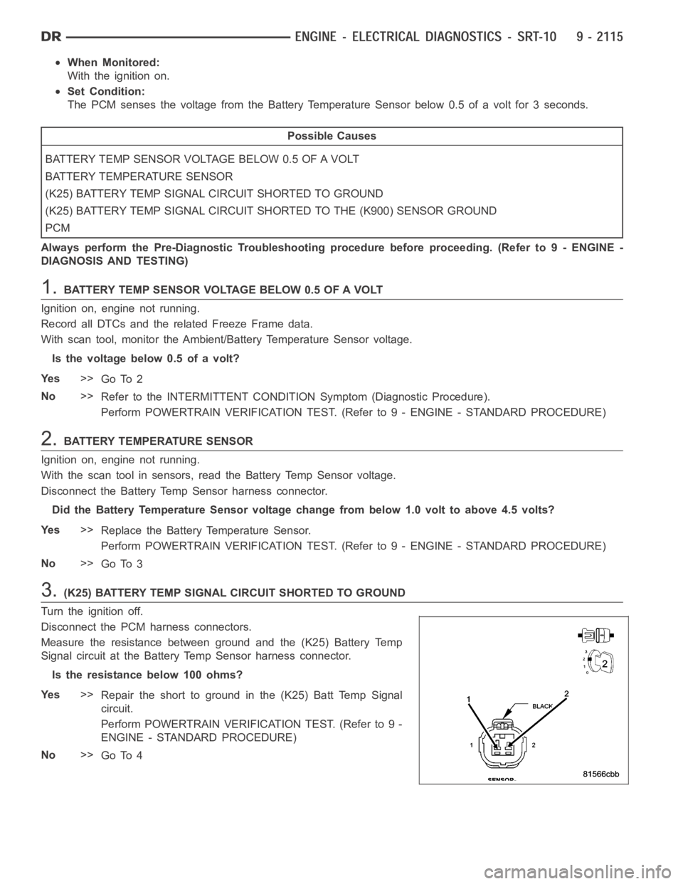
3.(K25) BATTERY TEMP SIGNAL CIRCUIT SHORTED TO GROUND
Turn the ignition off.
Disconnect the PCM harness connectors.
Measure the resistance between ground and the (K25) Battery Temp
Signal circuit at the Battery Temp Sensor harness connector.
Istheresistancebelow100ohms?
Ye s>>
Repair the short to ground in the (K25) Batt Temp Signal
circuit.
Perform POWERTRAIN VERIFICATION TEST. (Refer to 9 -
ENGINE - STANDARD PROCEDURE)
No>>
Go To 4
Page 1425 of 5267
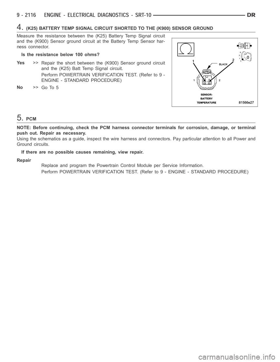
4.(K25) BATTERY TEMP SIGNAL CIRCUIT SHORTED TO THE (K900) SENSOR GROUND
Measure the resistance between the (K25) Battery Temp Signal circuit
and the (K900) Sensor ground circuit at the Battery Temp Sensor har-
ness connector.
Istheresistancebelow100ohms?
Ye s>>
Repair the short between the (K900) Sensor ground circuit
and the (K25) Batt Temp Signal circuit.
Perform POWERTRAIN VERIFICATION TEST. (Refer to 9 -
ENGINE - STANDARD PROCEDURE)
No>>
Go To 5
5.PCM
NOTE: Before continuing, check the PCM harness connector terminals for corrosion, damage, or terminal
push out. Repair as necessary.
Using the schematics as a guide, inspect the wire harness and connectors. Pay particular attention to all Power and
Ground circuits.
If there are no possible causes remaining, view repair.
Repair
Replace and program the Powertrain Control Module per Service Information.
Perform POWERTRAIN VERIFICATION TEST. (Refer to 9 - ENGINE - STANDARD PROCEDURE)
Page 1426 of 5267

P1494-LEAK DETECTION PUMP SWITCH OR MECHANICAL FAULT
For a complete wiring diagramRefer to Section 8W.
Page 1427 of 5267
When Monitored:
Immediately after a cold start, with battery/ambient temperature between 40 Deg. F and 90 Deg. F and coolant
temperature within 10 Deg. F of battery/ambient.
Set Condition:
The state of the switch does not change when the solenoid is energized.
Possible Causes
GOOD TRIP EQUAL TO ZERO
LDP VACUUM SUPPLY
LEAK DETECTION PUMP
(K107) LDP SWITCH SENSE CIRCUIT OPEN
(K107) LDP SWITCH SENSE CIRCUIT SHORTED TO GROUND
PCM
Always perform the Pre-Diagnostic Troubleshooting procedure before proceeding. (Refer to 9 - ENGINE -
DIAGNOSIS AND TESTING)
Diagnostic Test
1.VEHICLE HISTORY AND SERVICE BULLETIN INVESTIGATION
Ignition on, engine not running.
With a scan tool, read DTCs and record the related Freeze Frame data if any DTC(s) are present.
Whether or not any DTC(s) are present you will want to check the following items which may assist in repairing the
customer’s complaint successfully.
Check the vehicles repair history.
If the vehicle has a repair history that pertains to the customer’s currentcomplaint, review the repair.
Inspect the vehicle for any aftermarket accessories that may have been installed incorrectly.
Check for any service bulletin(s) related to the customer’s complaint or DTC(s).
If a service bulletin applies, follow the instructions per the service bulletin.
Choose the following scenario that best applies.
The service bulletin repaired the customer’s complaint.
Testing complete.
A DTC is present, no service bulletins apply, or the service bulletin didn’t repair the customer’s complaint.
Go To 2
2.GOOD TRIP EQUAL TO ZERO
Check for any related TSBs.
Ignition on, engine not running.
With the scan tool, read DTCs and record the related Freeze Frame data.
Is the Good Trip Counter displayed and equal to zero?
Ye s>>
Go To 3
No>>
Refer to the INTERMITTENT CONDITION Diagnostic Procedure.
Perform POWERTRAIN VERIFICATION TEST. (Refer to 9 - ENGINE - STANDARD PROCEDURE)
Page 1428 of 5267
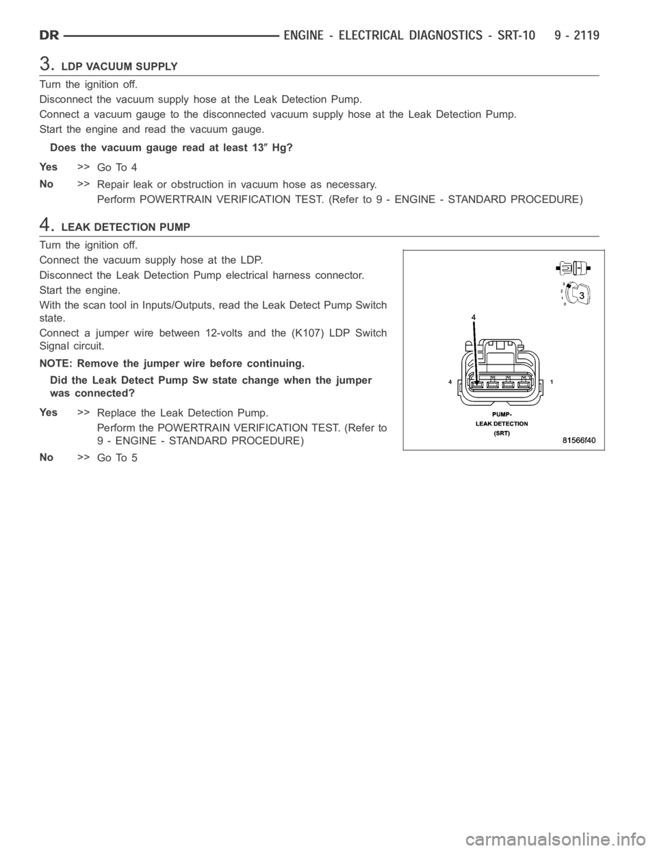
3.LDP VACUUM SUPPLY
Turn the ignition off.
Disconnect the vacuum supply hose at the Leak Detection Pump.
Connect a vacuum gauge to the disconnected vacuum supply hose at the Leak Detection Pump.
Start the engine and read the vacuum gauge.
Does the vacuum gauge read at least 13
Hg?
Ye s>>
Go To 4
No>>
Repair leak or obstruction in vacuum hose as necessary.
Perform POWERTRAIN VERIFICATION TEST. (Refer to 9 - ENGINE - STANDARD PROCEDURE)
4.LEAK DETECTION PUMP
Turn the ignition off.
Connect the vacuum supply hose at the LDP.
Disconnect the Leak Detection Pump electrical harness connector.
Start the engine.
With the scan tool in Inputs/Outputs, read the Leak Detect Pump Switch
state.
Connect a jumper wire between 12-volts and the (K107) LDP Switch
Signal circuit.
NOTE: Remove the jumper wire before continuing.
Did the Leak Detect Pump Sw state change when the jumper
was connected?
Ye s>>
Replace the Leak Detection Pump.
Perform the POWERTRAIN VERIFICATION TEST. (Refer to
9 - ENGINE - STANDARD PROCEDURE)
No>>
Go To 5
Page 1429 of 5267
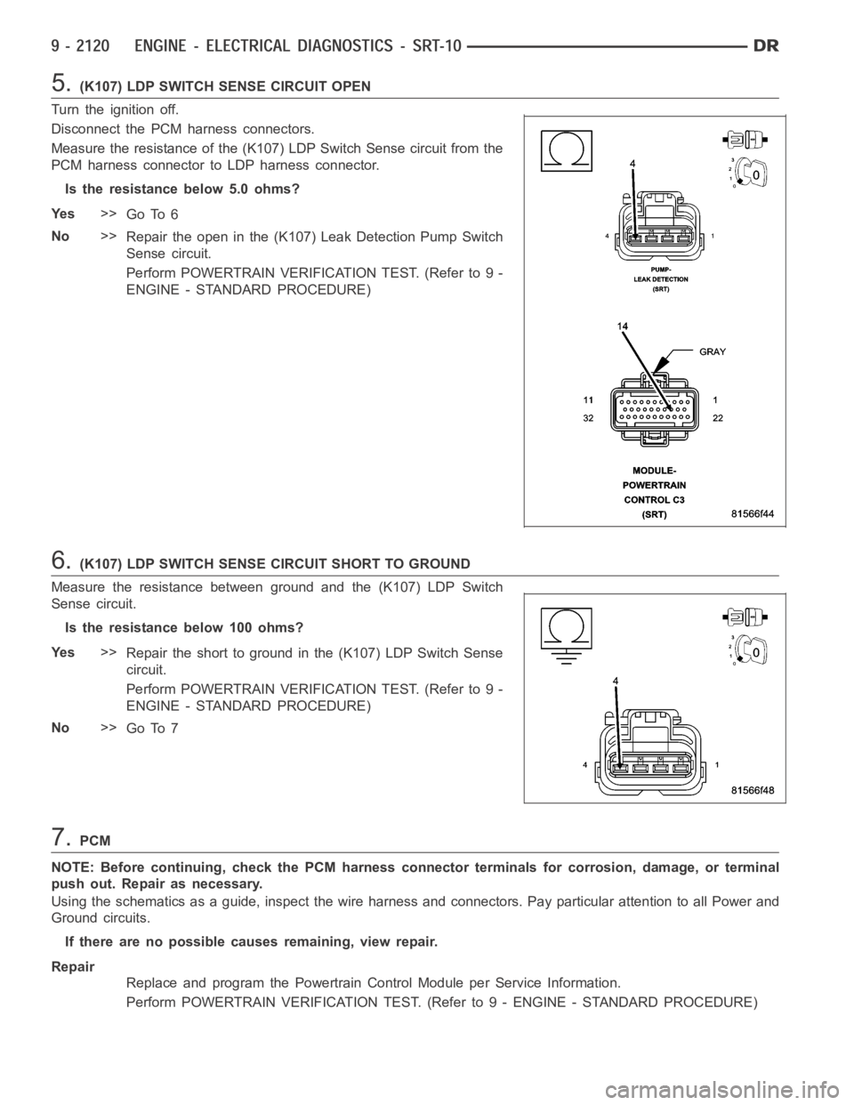
5.(K107) LDP SWITCH SENSE CIRCUIT OPEN
Turn the ignition off.
Disconnect the PCM harness connectors.
Measure the resistance of the (K107) LDP Switch Sense circuit from the
PCM harness connector to LDP harness connector.
Is the resistance below 5.0 ohms?
Ye s>>
Go To 6
No>>
Repair the open in the (K107) Leak Detection Pump Switch
Sense circuit.
Perform POWERTRAIN VERIFICATION TEST. (Refer to 9 -
ENGINE - STANDARD PROCEDURE)
6.(K107) LDP SWITCH SENSE CIRCUIT SHORT TO GROUND
Measure the resistance between ground and the (K107) LDP Switch
Sense circuit.
Istheresistancebelow100ohms?
Ye s>>
Repair the short to ground in the (K107) LDP Switch Sense
circuit.
Perform POWERTRAIN VERIFICATION TEST. (Refer to 9 -
ENGINE - STANDARD PROCEDURE)
No>>
Go To 7
7.PCM
NOTE: Before continuing, check the PCM harness connector terminals for corrosion, damage, or terminal
push out. Repair as necessary.
Using the schematics as a guide, inspect the wire harness and connectors. Pay particular attention to all Power and
Ground circuits.
If there are no possible causes remaining, view repair.
Repair
Replace and program the Powertrain Control Module per Service Information.
Perform POWERTRAIN VERIFICATION TEST. (Refer to 9 - ENGINE - STANDARD PROCEDURE)
Page 1430 of 5267

P1495-LEAK DETECTION PUMP SOLENOID CIRCUIT
For a complete wiring diagramRefer to Section 8W.