DODGE RAM SRT-10 2006 Service Repair Manual
RAM SRT-10 2006
DODGE
DODGE
https://www.carmanualsonline.info/img/12/56917/w960_56917-0.png
DODGE RAM SRT-10 2006 Service Repair Manual
Trending: differential, ECU, spark plugs replace, battery capacity, AUX, rims, Water pump
Page 2541 of 5267
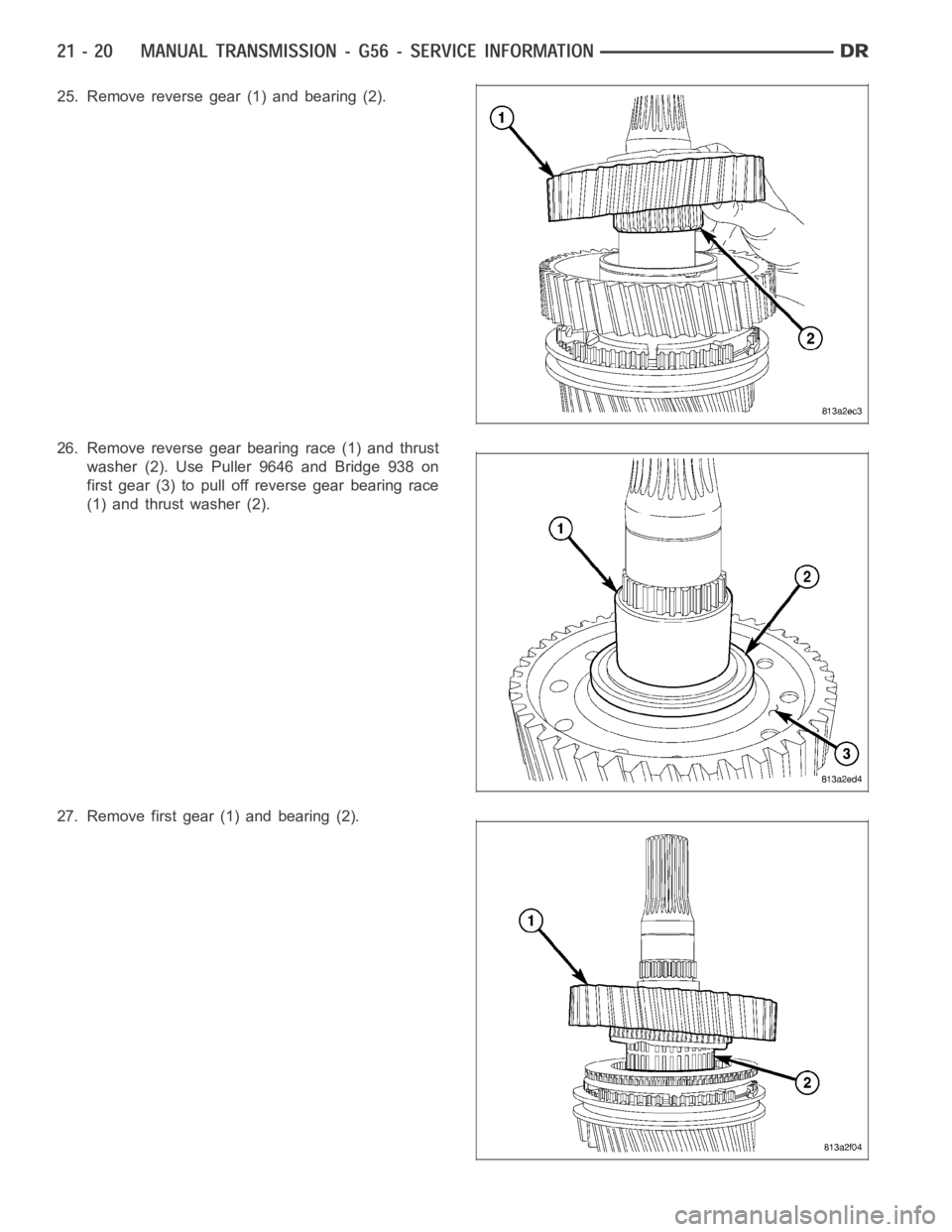
25. Remove reverse gear (1) and bearing (2).
26. Remove reverse gear bearing race (1) and thrust
washer (2). Use Puller 9646 and Bridge 938 on
first gear (3) to pull off reverse gear bearing race
(1) and thrust washer (2).
27. Remove first gear (1) and bearing (2).
Page 2542 of 5267
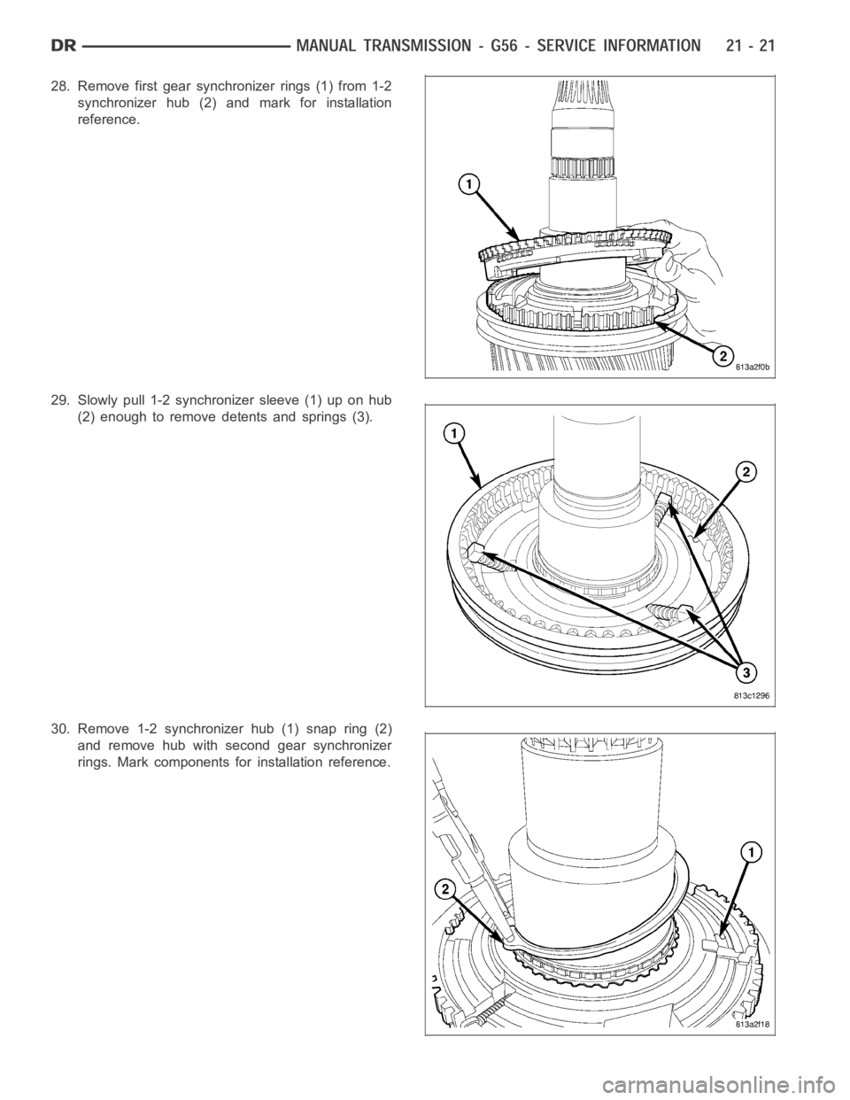
28. Remove first gear synchronizer rings (1) from 1-2
synchronizer hub (2) and mark for installation
reference.
29. Slowly pull 1-2 synchronizer sleeve (1) up on hub
(2) enough to remove detents and springs (3).
30. Remove 1-2 synchronizer hub (1) snap ring (2)
and remove hub with second gear synchronizer
rings. Mark components for installation reference.
Page 2543 of 5267
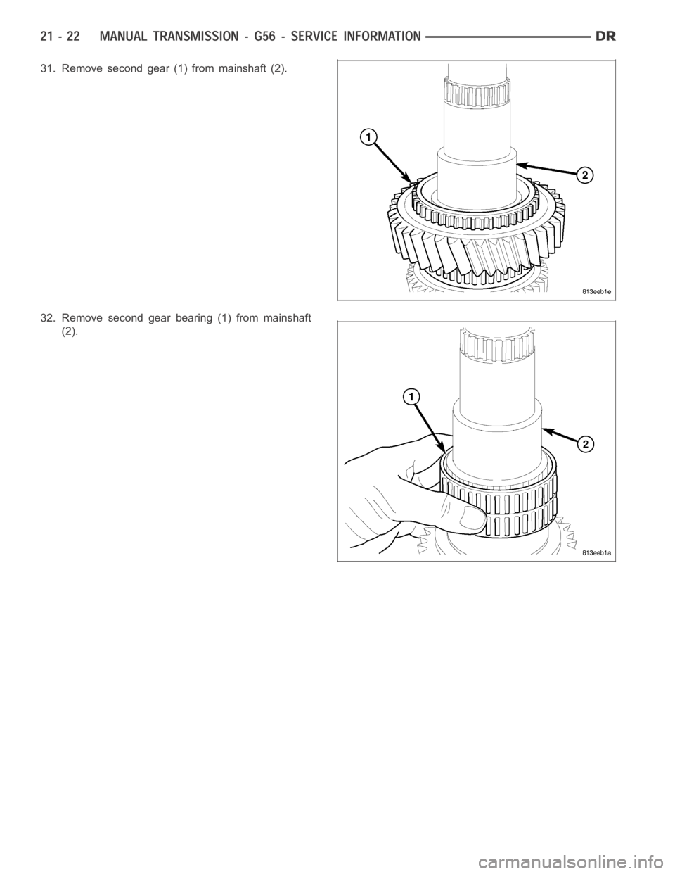
31. Remove second gear (1) from mainshaft (2).
32. Remove second gear bearing (1) from mainshaft
(2).
Page 2544 of 5267
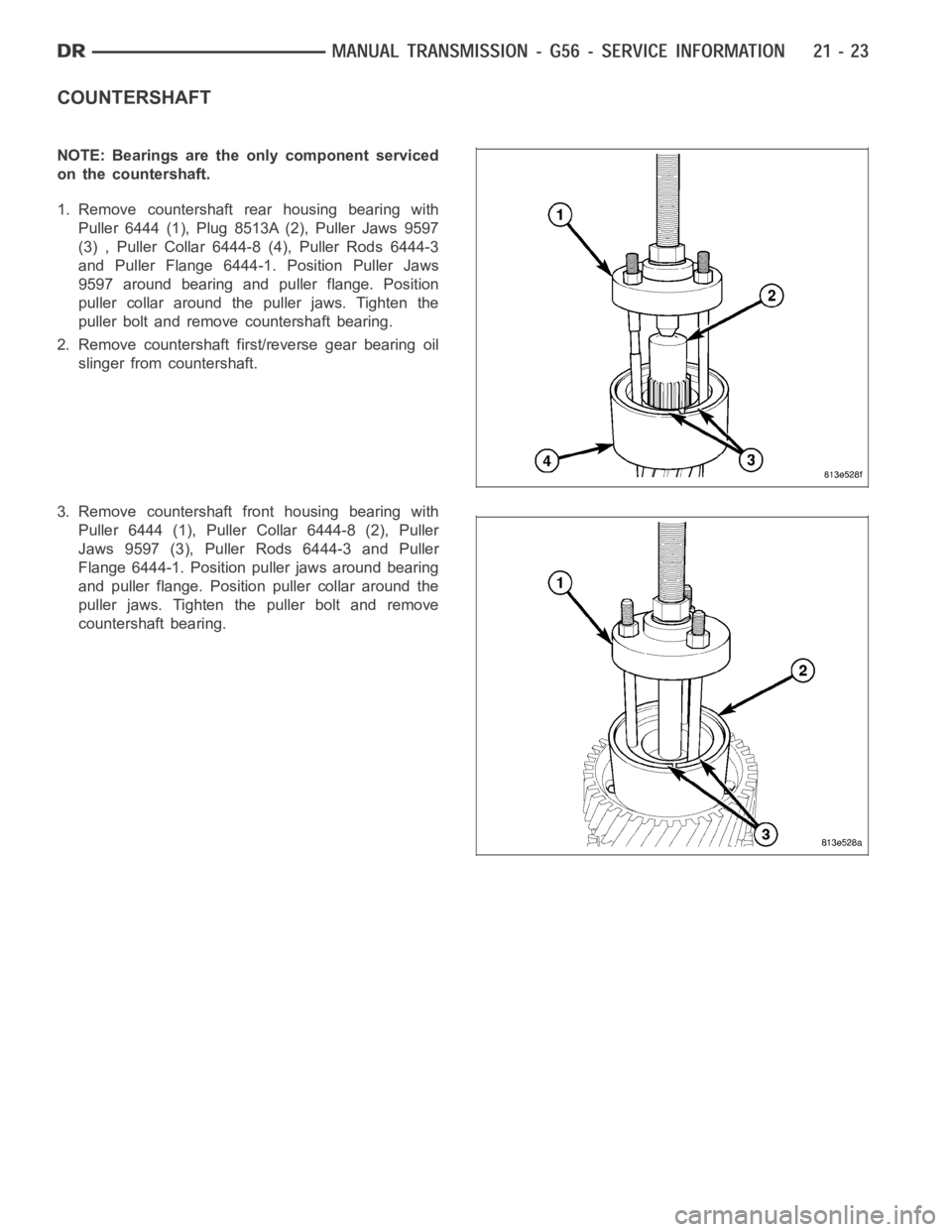
COUNTERSHAFT
NOTE: Bearings are the only component serviced
on the countershaft.
1. Remove countershaft rear housing bearing with
Puller 6444 (1), Plug 8513A (2), Puller Jaws 9597
(3) , Puller Collar 6444-8 (4), Puller Rods 6444-3
and Puller Flange 6444-1. Position Puller Jaws
9597 around bearing and puller flange. Position
puller collar around the puller jaws. Tighten the
puller bolt and remove countershaft bearing.
2. Remove countershaft first/reverse gear bearing oil
slinger from countershaft.
3. Remove countershaft front housing bearing with
Puller 6444 (1), Puller Collar 6444-8 (2), Puller
Jaws 9597 (3), Puller Rods 6444-3 and Puller
Flange 6444-1. Position puller jaws around bearing
and puller flange. Position puller collar around the
puller jaws. Tighten the puller bolt and remove
countershaft bearing.
Page 2545 of 5267
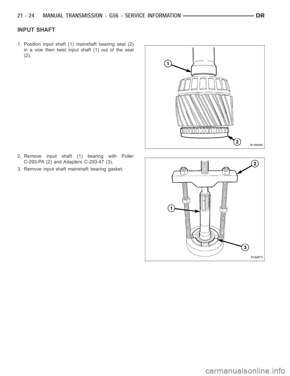
INPUT SHAFT
1. Position input shaft (1) mainshaft bearing seal (2)
in a vice then twist input shaft (1) out of the seal
(2).
2. Remove input shaft (1) bearing with Puller
C-293-PA (2) and Adapters C-293-47 (3).
3. Remove input shaft mainshaft bearing gasket.
Page 2546 of 5267
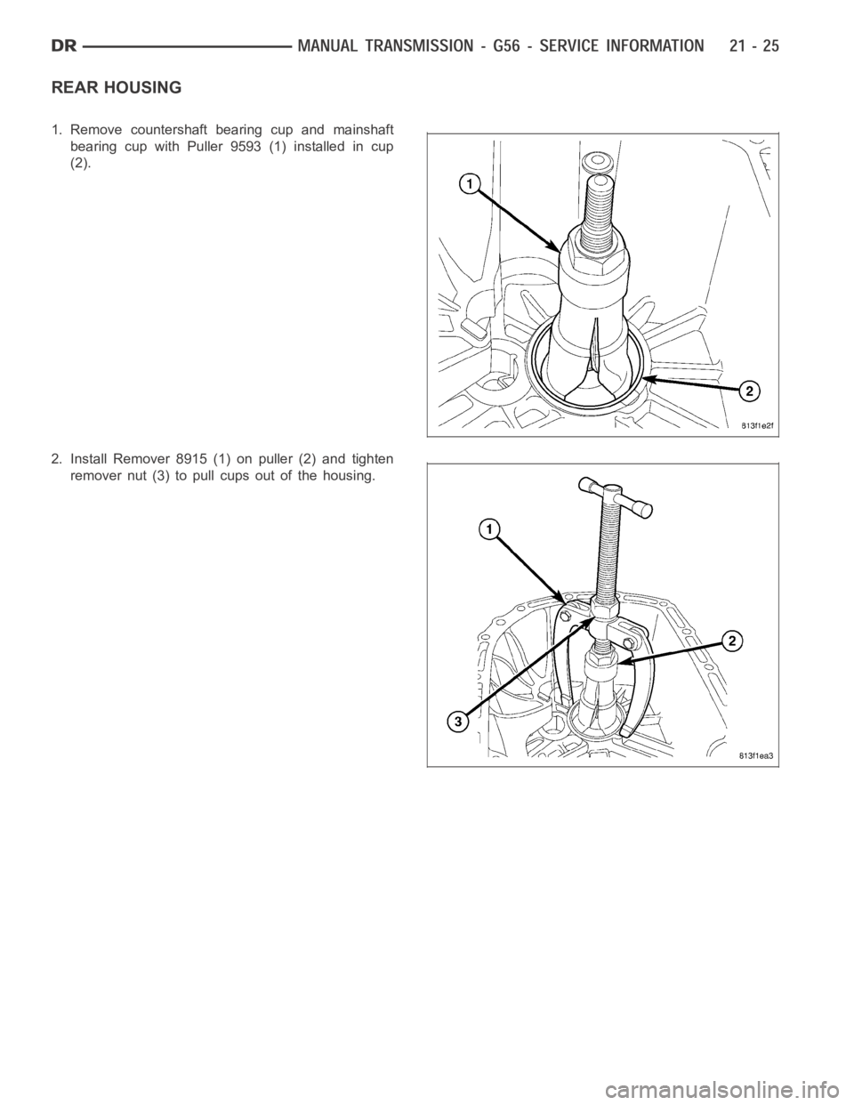
REAR HOUSING
1. Remove countershaft bearing cup and mainshaft
bearing cup with Puller 9593 (1) installed in cup
(2).
2. Install Remover 8915 (1) on puller (2) and tighten
remover nut (3) to pull cups out of the housing.
Page 2547 of 5267
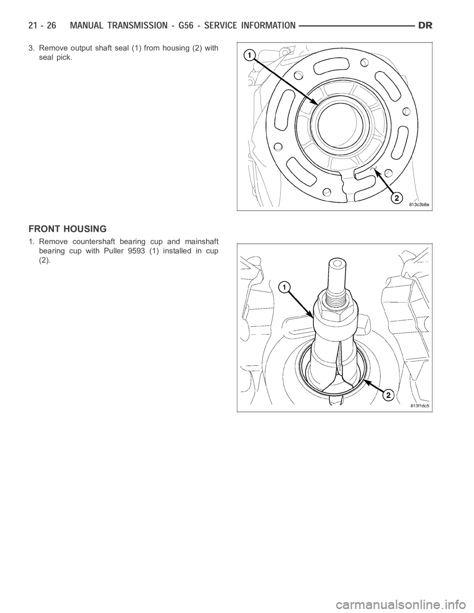
3. Remove output shaft seal (1) from housing (2) with
seal pick.
FRONT HOUSING
1. Remove countershaft bearing cup and mainshaft
bearing cup with Puller 9593 (1) installed in cup
(2).
Page 2548 of 5267
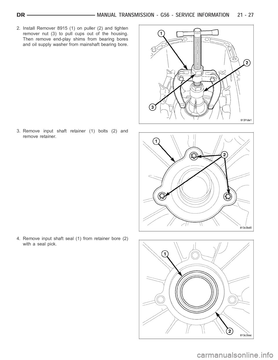
2. Install Remover 8915 (1) on puller (2) and tighten
remover nut (3) to pull cups out of the housing.
Then remove end-play shims from bearing bores
and oil supply washer from mainshaft bearing bore.
3. Remove input shaft retainer (1) bolts (2) and
remove retainer.
4. Remove input shaft seal (1) from retainer bore (2)
with a seal pick.
Page 2549 of 5267
CLEANING
Clean gears, shafts, shift components and transmission housings with a standard parts cleaning solvent. Do not use
acid or corrosive base solvents. Dry all parts except bearings with compressed air.
Clean shaft bearings with a mild solvent such as MOPAR
degreasing solvent, Gunkor similar solvents. Do not
dry the bearings with compressed air. Allow the bearings to either air dry or wipe them dry with clean shop towels.
INSPECTION
NOTE: Minor corrosion, nicks, or pitting can be
smoothed with 400 grit emery and polished out
with crocus cloth.
Bearings:Inspect for worn, chipped, cracked, flat-
spotted or brinnelled.
Gears:Inspect for worn, chipped or cracked teeth.
Inspect bearing surfaces for wear or flat-spotted.
Mainshaft:Inspect for worn splines, snap ring
grooves and threads.
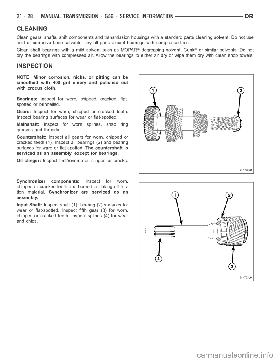
Countershaft:Inspect all gears for worn, chipped or
cracked teeth (1). Inspect all bearings (2) and bearing
surfaces for ware or flat-spotted.The countershaft is
serviced as an assembly, except for bearings.
Oil slinger:Inspect first/reverse oil slinger for cracks.
Synchronizer components:Inspect for worn,
chipped or cracked teeth and burned or flaking off fric-
tion material.Synchronizer are serviced as an
assembly.
Input Shaft:Inspect shaft (1), bearing (2) surfaces for
wear or flat-spotted. Inspect fifth gear (3) for worn,
chipped or cracked teeth. Inspect splines (4) for wear
and chips.
Page 2550 of 5267
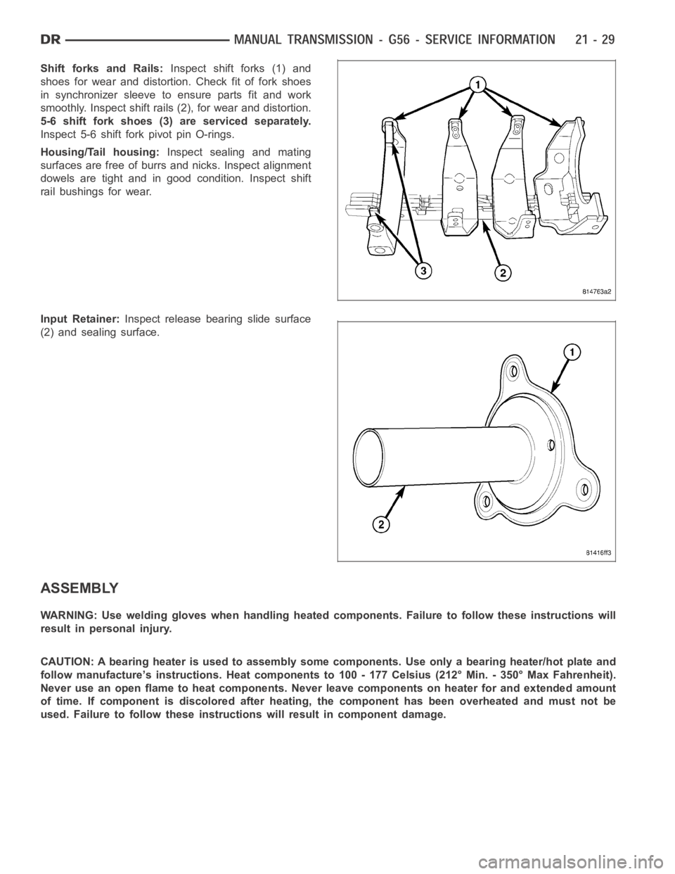
Shift forks and Rails:Inspect shift forks (1) and
shoes for wear and distortion. Check fit of fork shoes
in synchronizer sleeve to ensure parts fit and work
smoothly. Inspect shift rails(2), for wear and distortion.
5-6 shift fork shoes (3) are serviced separately.
Inspect 5-6 shift fork pivot pin O-rings.
Housing/Tail housing:Inspect sealing and mating
surfaces are free of burrs and nicks. Inspect alignment
dowels are tight and in good condition. Inspect shift
rail bushings for wear.
Input Retainer:Inspect release bearing slide surface
(2) and sealing surface.
ASSEMBLY
WARNING: Use welding gloves when handling heated components. Failure to follow these instructions will
result in personal injury.
CAUTION:Abearingheaterisusedtoassemblysomecomponents.Useonlyabearing heater/hot plate and
follow manufacture’s instructions. Heat components to 100 - 177 Celsius (212° Min. - 350° Max Fahrenheit).
Never use an open flame to heat components. Never leave components on heater for and extended amount
of time. If component is discolored after heating, the component has been overheated and must not be
used. Failure to follow these instructions will result in component damage.
Trending: fuses, open hood, parking brake, air condition, open gas tank, transmission fluid, diagnostic menu
