DODGE RAM SRT-10 2006 Service Repair Manual
RAM SRT-10 2006
DODGE
DODGE
https://www.carmanualsonline.info/img/12/56917/w960_56917-0.png
DODGE RAM SRT-10 2006 Service Repair Manual
Trending: engine oil capacity, spark plugs, AUX, ground clearance, heater, sunroof, diagram
Page 2571 of 5267
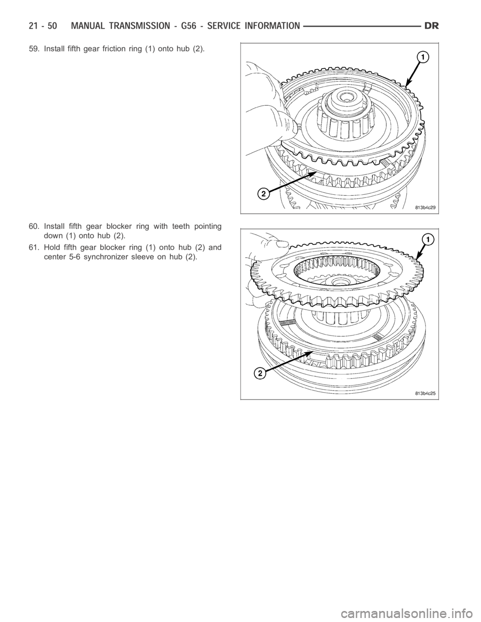
59. Install fifth gear friction ring (1) onto hub (2).
60. Install fifth gear blocker ring with teeth pointing
down (1) onto hub (2).
61. Hold fifth gear blocker ring (1) onto hub (2) and
center 5-6 synchronizer sleeve on hub (2).
Page 2572 of 5267
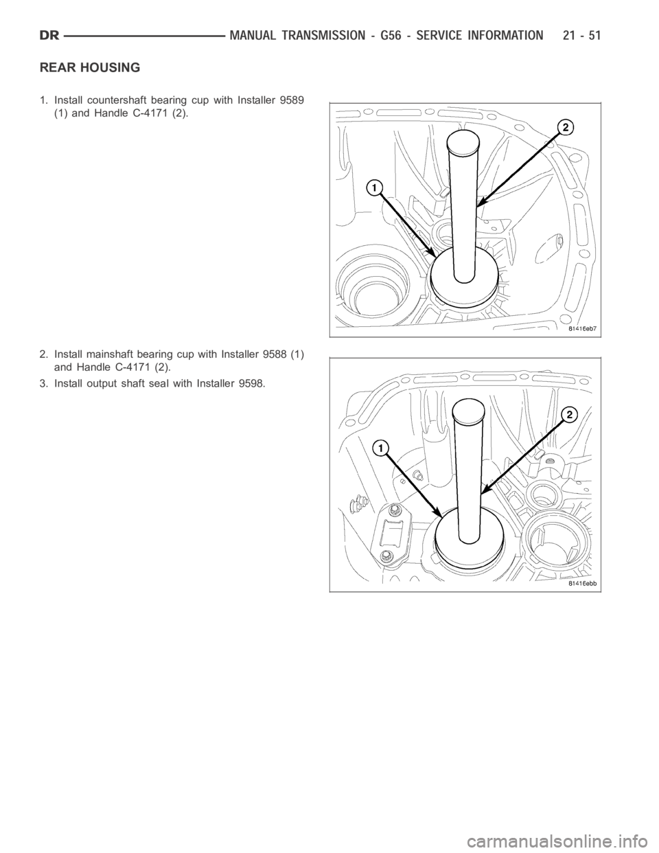
REAR HOUSING
1. Install countershaft bearing cup with Installer 9589
(1) and Handle C-4171 (2).
2. Install mainshaft bearing cup with Installer 9588 (1)
and Handle C-4171 (2).
3. Install output shaft seal with Installer 9598.
Page 2573 of 5267
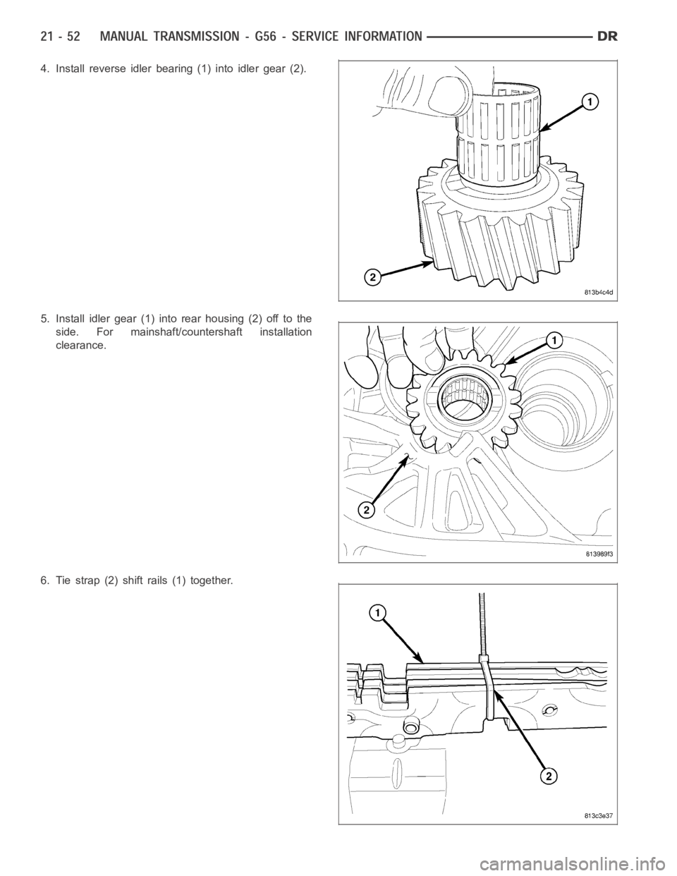
4. Install reverse idler bearing (1) into idler gear (2).
5. Install idler gear (1) into rear housing (2) off to the
side. For mainshaft/countershaft installation
clearance.
6. Tie strap (2) shift rails (1) together.
Page 2574 of 5267
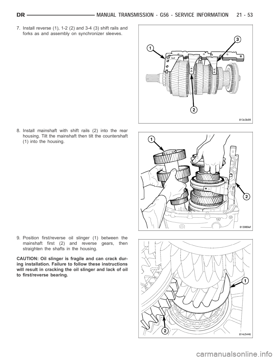
7. Install reverse (1), 1-2 (2) and 3-4 (3) shift rails and
forks as and assembly on synchronizer sleeves.
8. Install mainshaft with shift rails (2) into the rear
housing. Tilt the mainshaft then tilt the countershaft
(1) into the housing.
9. Position first/reverse oil slinger (1) between the
mainshaft first (2) and reverse gears, then
straighten the shafts in the housing.
CAUTION: Oil slinger is fragile and can crack dur-
ing installation. Failure to follow these instructions
will result in cracking the oil slinger and lack of oil
to first/reverse bearing.
Page 2575 of 5267
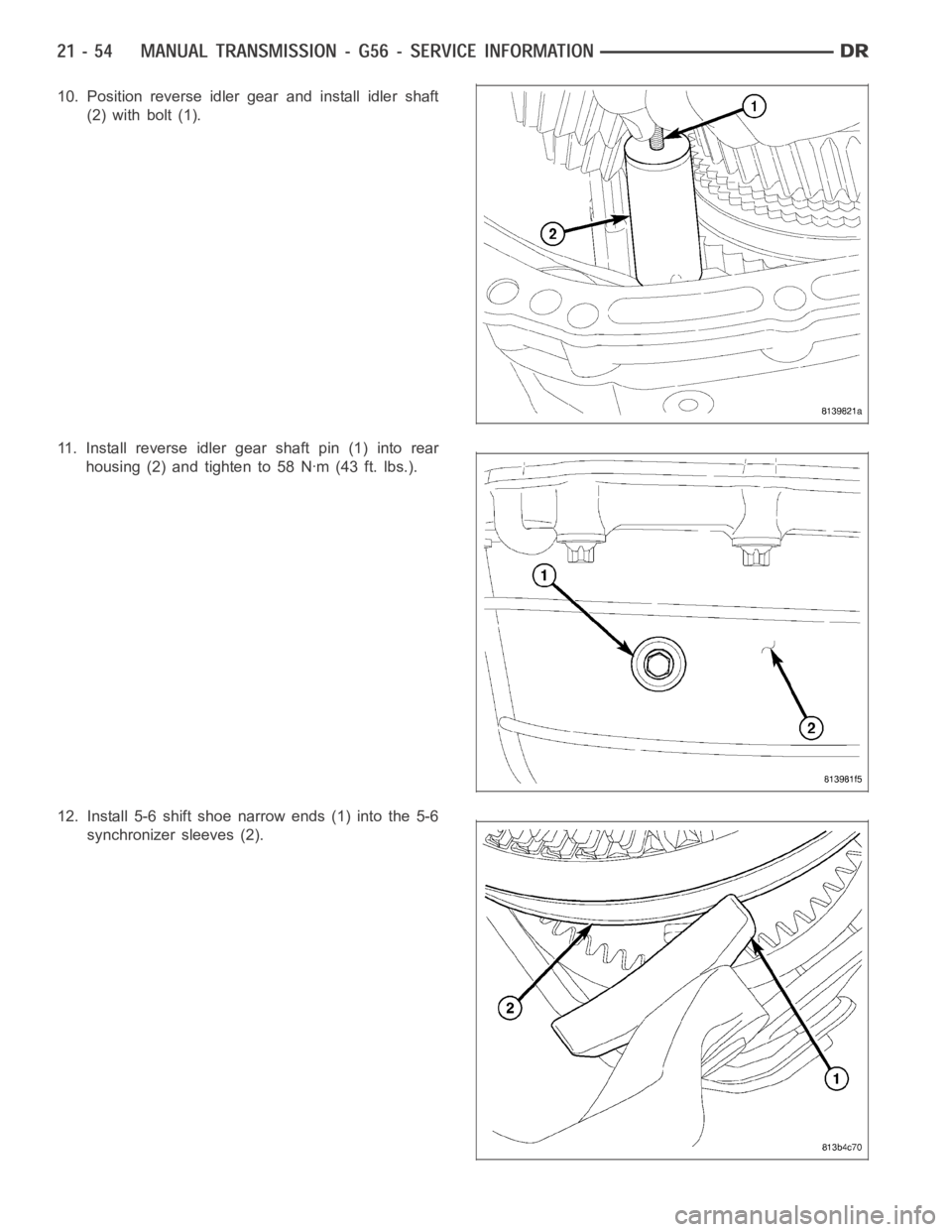
10. Position reverse idler gear and install idler shaft
(2) with bolt (1).
11. Install reverse idler gear shaft pin (1) into rear
housing (2) and tighten to 58 Nꞏm (43 ft. lbs.).
12. Install 5-6 shift shoe narrow ends (1) into the 5-6
synchronizer sleeves (2).
Page 2576 of 5267
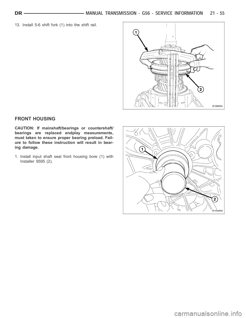
13. Install 5-6 shift fork (1) into the shift rail.
FRONT HOUSING
CAUTION: If mainshaft/bearings or countershaft/
bearings are replaced endplay measurements,
must taken to ensure proper bearing preload. Fail-
ure to follow these instruction will result in bear-
ing damage.
1. Install input shaft seal front housing bore (1) with
Installer 9595 (2).
Page 2577 of 5267
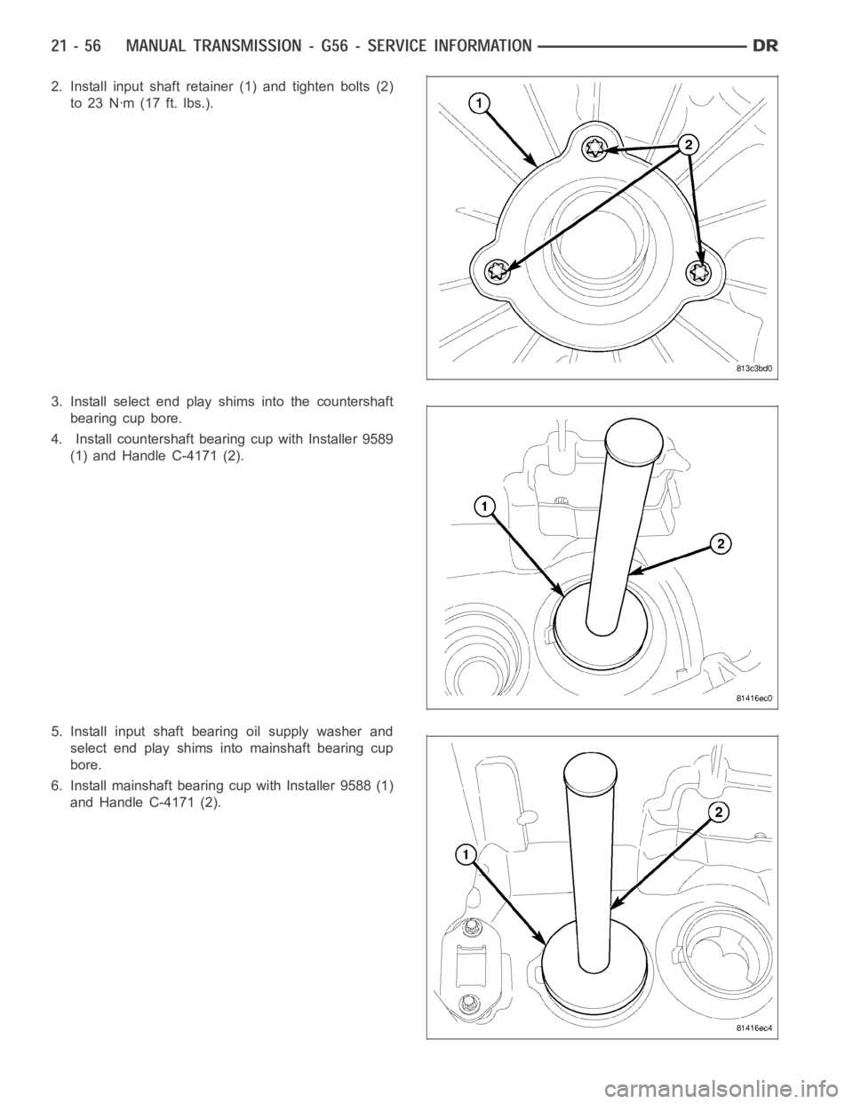
2. Install input shaft retainer (1) and tighten bolts (2)
to 23 Nꞏm (17 ft. lbs.).
3. Install select end play shims into the countershaft
bearing cup bore.
4. Install countershaft bearing cup with Installer 9589
(1) and Handle C-4171 (2).
5. Install input shaft bearing oil supply washer and
select end play shims into mainshaft bearing cup
bore.
6. Install mainshaft bearing cup with Installer 9588 (1)
and Handle C-4171 (2).
Page 2578 of 5267
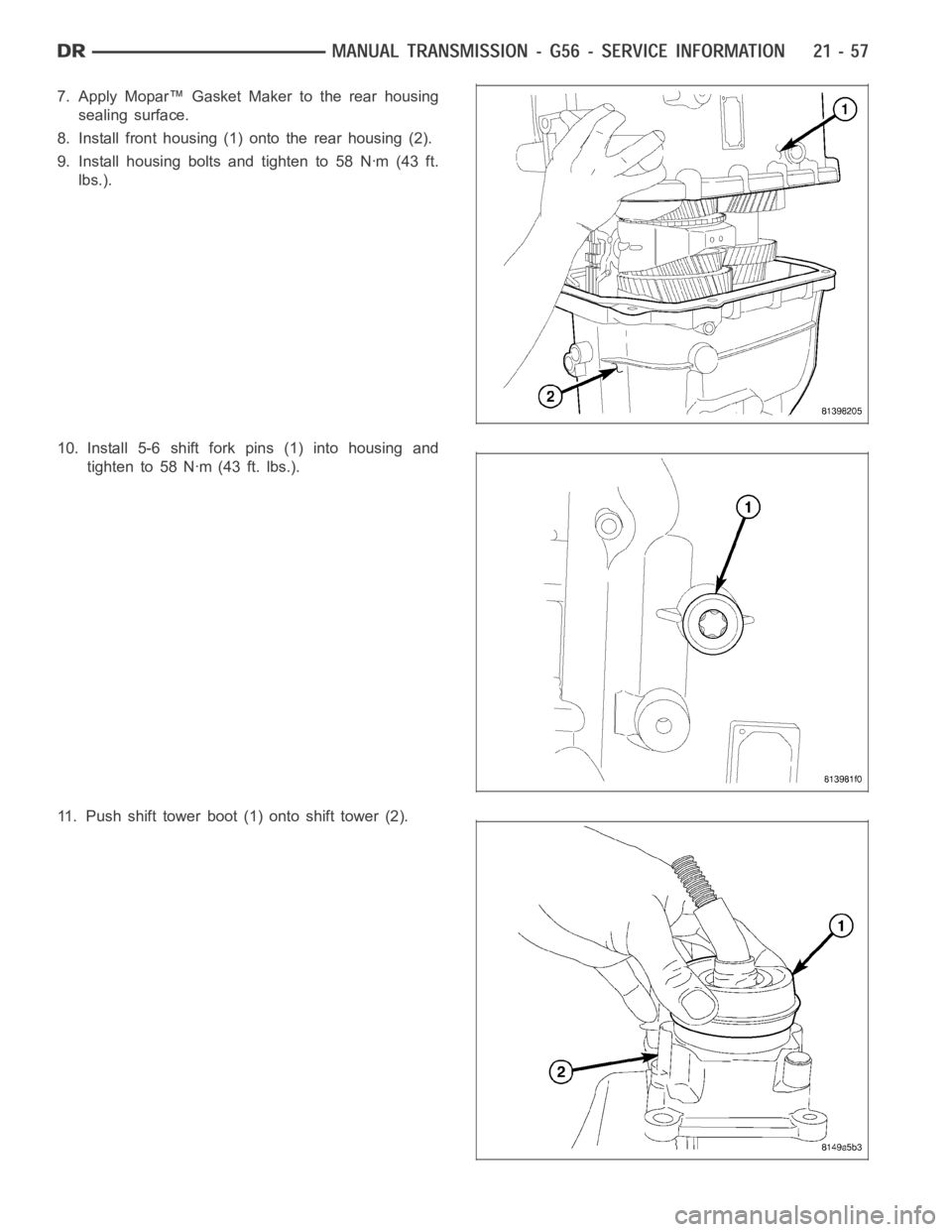
7. Apply Mopar™ Gasket Maker to the rear housing
sealing surface.
8. Install front housing (1) onto the rear housing (2).
9. Install housing bolts and tighten to 58 Nꞏm (43 ft.
lbs.).
10. Install 5-6 shift fork pins (1) into housing and
tighten to 58 Nꞏm (43 ft. lbs.).
11. Push shift tower boot (1) onto shift tower (2).
Page 2579 of 5267
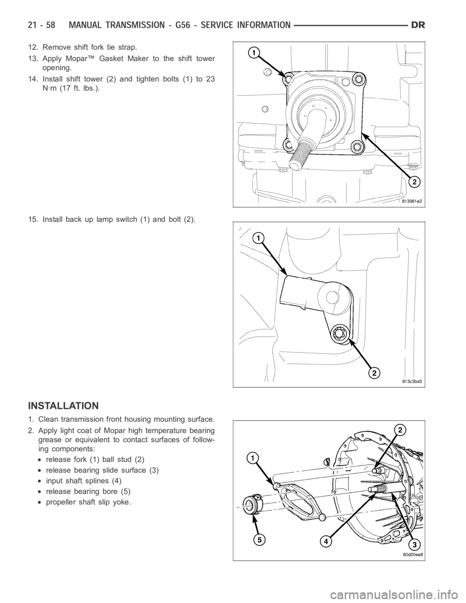
12. Remove shift fork tie strap.
13. Apply Mopar™ Gasket Maker to the shift tower
opening.
14. Install shift tower (2) and tighten bolts (1) to 23
Nꞏm (17 ft. lbs.).
15. Install back up lamp switch (1) and bolt (2).
INSTALLATION
1. Clean transmission front housing mounting surface.
2. Apply light coat of Mopar high temperature bearing
grease or equivalent to contact surfaces of follow-
ing components:
release fork (1) ball stud (2)
release bearing slide surface (3)
input shaft splines (4)
release bearing bore (5)
propeller shaft slip yoke.
Page 2580 of 5267
3. Support and secure transmission to jack.
4. Raise and align transmission input shaft with clutch
disc, then slide transmission into place.
5. Install exhaust bracket diesel engine.
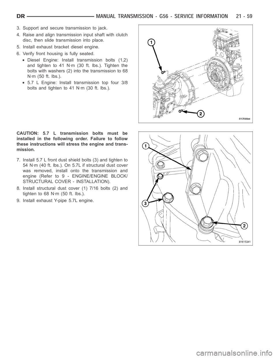
6. Verify front housing is fully seated.
Diesel Engine: Install transmission bolts (1,2)
and tighten to 41 Nꞏm (30 ft. lbs.). Tighten the
bolts with washers (2) into the transmission to 68
Nꞏm (50 ft. lbs.).
5.7 L Engine: Install transmission top four 3/8
bolts and tighten to 41 Nꞏm (30 ft. lbs.).
CAUTION: 5.7 L transmission bolts must be
installed in the followingorder. Failure to follow
these instructions will stress the engine and trans-
mission.
7. Install 5.7 L front dust shield bolts (3) and tighten to
54 Nꞏm (40 ft. lbs.). On 5.7L if structural dust cover
was removed, install onto the transmission and
engine (Refer to 9 - ENGINE/ENGINE BLOCK/
STRUCTURAL COVER - INSTALLATION).
8. Install structural dust cover (1) 7/16 bolts (2) and
tighten to 68 Nꞏm (50 ft. lbs.).
9. Install exhaust Y-pipe 5.7L engine.
Trending: lug pattern, warning light, overheating, snow chains, steering, gas tank size, odometer
