DODGE RAM SRT-10 2006 Service Repair Manual
RAM SRT-10 2006
DODGE
DODGE
https://www.carmanualsonline.info/img/12/56917/w960_56917-0.png
DODGE RAM SRT-10 2006 Service Repair Manual
Trending: charging, interior lights, airbag off, rear view mirror, gas tank size, hood release, open gas tank
Page 2531 of 5267
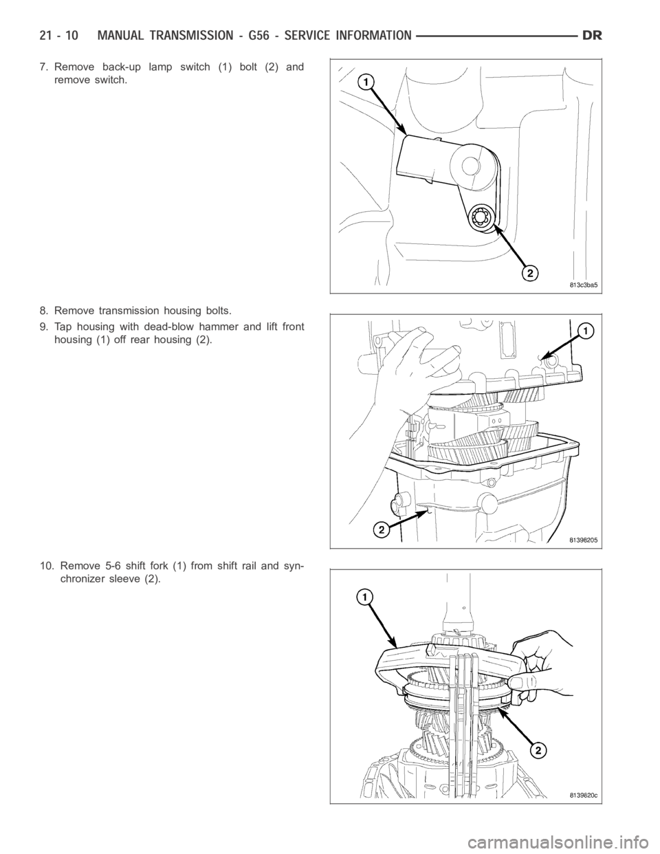
7. Remove back-up lamp switch (1) bolt (2) and
remove switch.
8. Remove transmission housing bolts.
9. Tap housing with dead-blow hammer and lift front
housing (1) off rear housing (2).
10. Remove 5-6 shift fork (1) from shift rail and syn-
chronizer sleeve (2).
Page 2532 of 5267
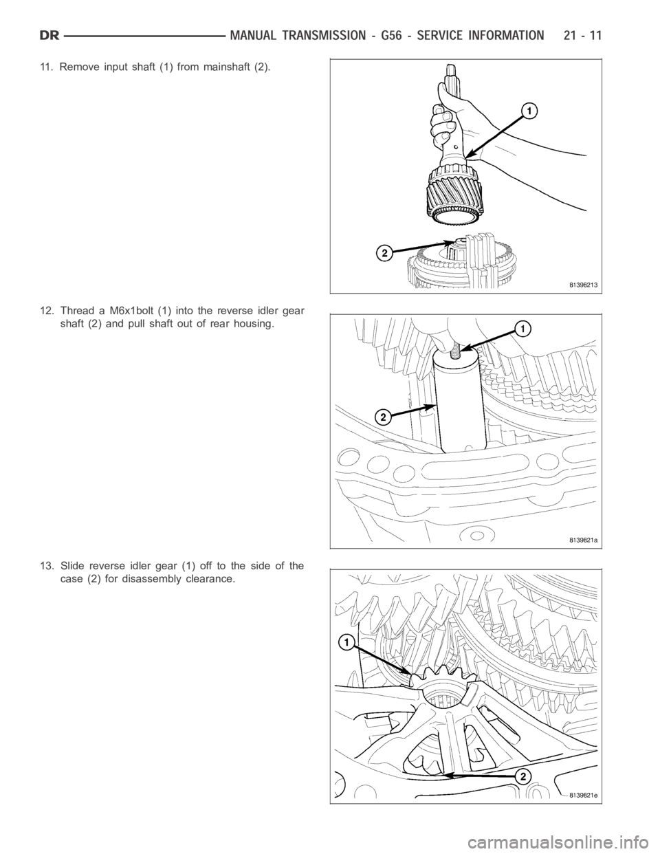
11. Remove input shaft (1) from mainshaft (2).
12. Thread a M6x1bolt (1) into the reverse idler gear
shaft (2) and pull shaft out of rear housing.
13. Slide reverse idler gear (1) off to the side of the
case (2) for disassembly clearance.
Page 2533 of 5267
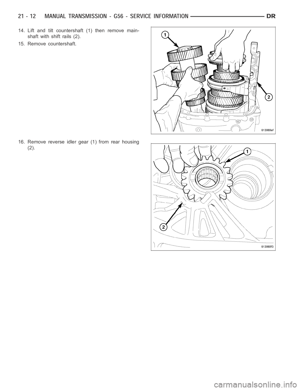
14. Lift and tilt countershaft (1) then remove main-
shaft with shift rails (2).
15. Remove countershaft.
16. Remove reverse idler gear (1) from rear housing
(2).
Page 2534 of 5267
MAINSHAFT
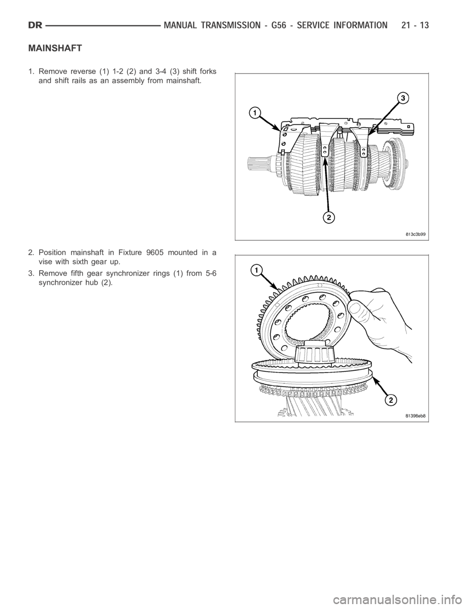
1. Remove reverse (1) 1-2 (2) and 3-4 (3) shift forks
and shift rails as an assembly from mainshaft.
2. Position mainshaft in Fixture 9605 mounted in a
vise with sixth gear up.
3. Remove fifth gear synchronizer rings (1) from 5-6
synchronizer hub (2).
Page 2535 of 5267
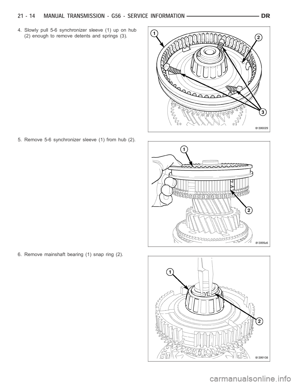
4. Slowly pull 5-6 synchronizer sleeve (1) up on hub
(2) enough to remove detents and springs (3).
5. Remove 5-6 synchronizer sleeve (1) from hub (2).
6. Remove mainshaft bearing (1) snap ring (2).
Page 2536 of 5267
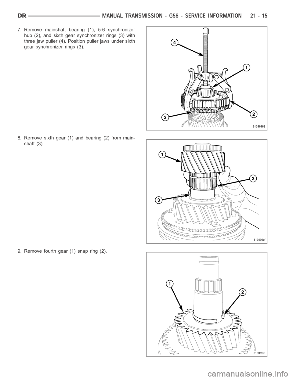
7. Remove mainshaft bearing (1), 5-6 synchronizer
hub (2), and sixth gear synchronizer rings (3) with
three jaw puller (4). Position puller jaws under sixth
gear synchronizer rings (3).
8. Remove sixth gear (1) and bearing (2) from main-
shaft (3).
9. Remove fourth gear (1) snap ring (2).
Page 2537 of 5267
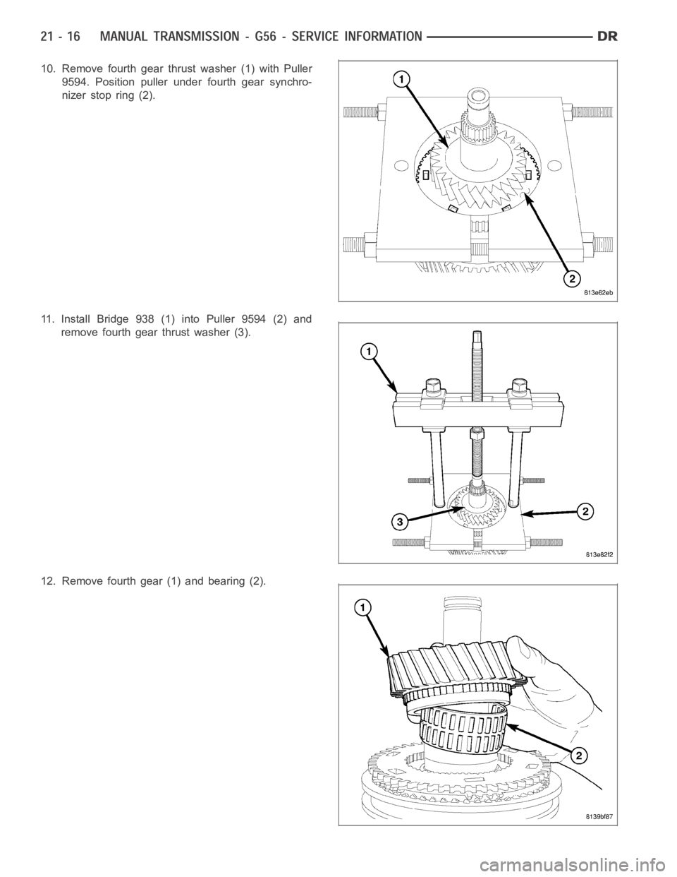
10. Remove fourth gear thrust washer (1) with Puller
9594. Position puller under fourth gear synchro-
nizer stop ring (2).
11. Install Bridge 938 (1) into Puller 9594 (2) and
remove fourth gear thrust washer (3).
12. Remove fourth gear (1) and bearing (2).
Page 2538 of 5267
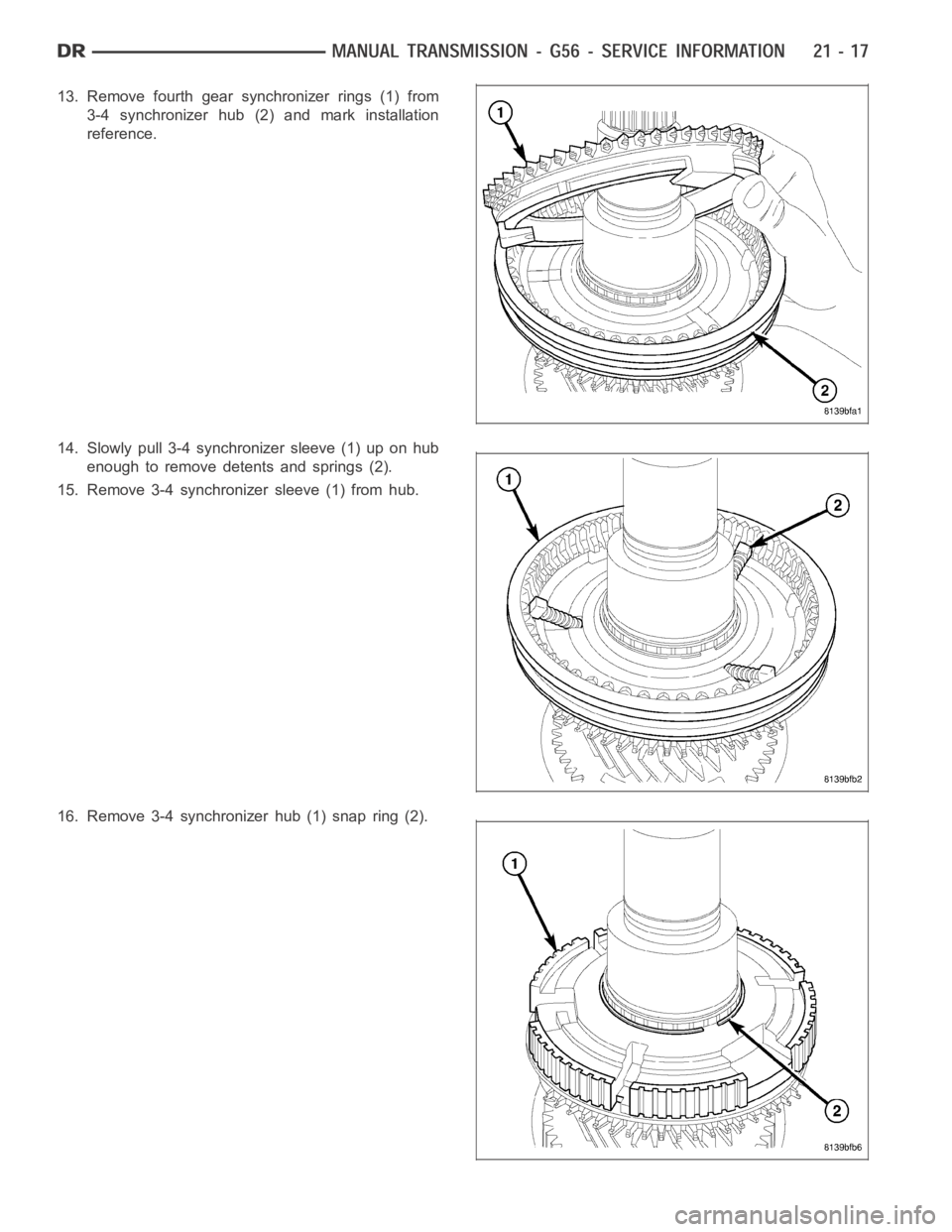
13. Remove fourth gear synchronizer rings (1) from
3-4 synchronizer hub (2) and mark installation
reference.
14. Slowly pull 3-4 synchronizer sleeve (1) up on hub
enough to remove detents and springs (2).
15. Remove 3-4 synchronizer sleeve (1) from hub.
16. Remove 3-4 synchronizer hub (1) snap ring (2).
Page 2539 of 5267
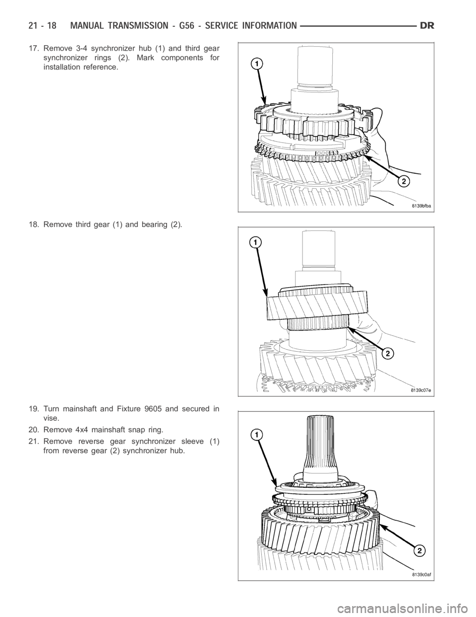
17. Remove 3-4 synchronizer hub (1) and third gear
synchronizer rings (2). Mark components for
installation reference.
18. Remove third gear (1) and bearing (2).
19. Turn mainshaft and Fixture 9605 and secured in
vise.
20. Remove 4x4 mainshaft snap ring.
21. Remove reverse gear synchronizer sleeve (1)
from reverse gear (2) synchronizer hub.
Page 2540 of 5267
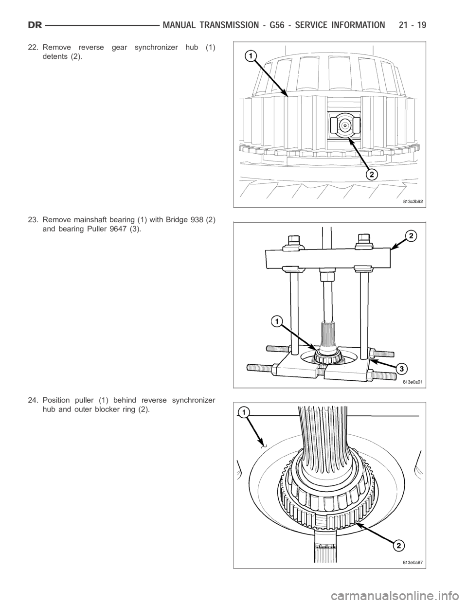
22. Remove reverse gear synchronizer hub (1)
detents (2).
23. Remove mainshaft bearing (1) with Bridge 938 (2)
and bearing Puller 9647 (3).
24. Position puller (1) behind reverse synchronizer
hub and outer blocker ring (2).
Trending: warning, oil change, tire size, fuel tank removal, key, parking sensors, brakes
