DODGE RAM SRT-10 2006 Service Repair Manual
RAM SRT-10 2006
DODGE
DODGE
https://www.carmanualsonline.info/img/12/56917/w960_56917-0.png
DODGE RAM SRT-10 2006 Service Repair Manual
Trending: brakes, battery, key, fuel pump, turn signal, spark plugs replace, airbag disable
Page 4461 of 5267
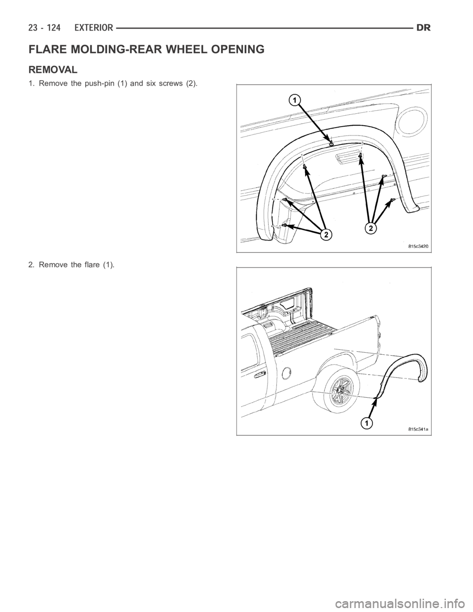
FLARE MOLDING-REAR WHEEL OPENING
REMOVAL
1. Remove the push-pin (1) and six screws (2).
2. Remove the flare (1).
Page 4462 of 5267
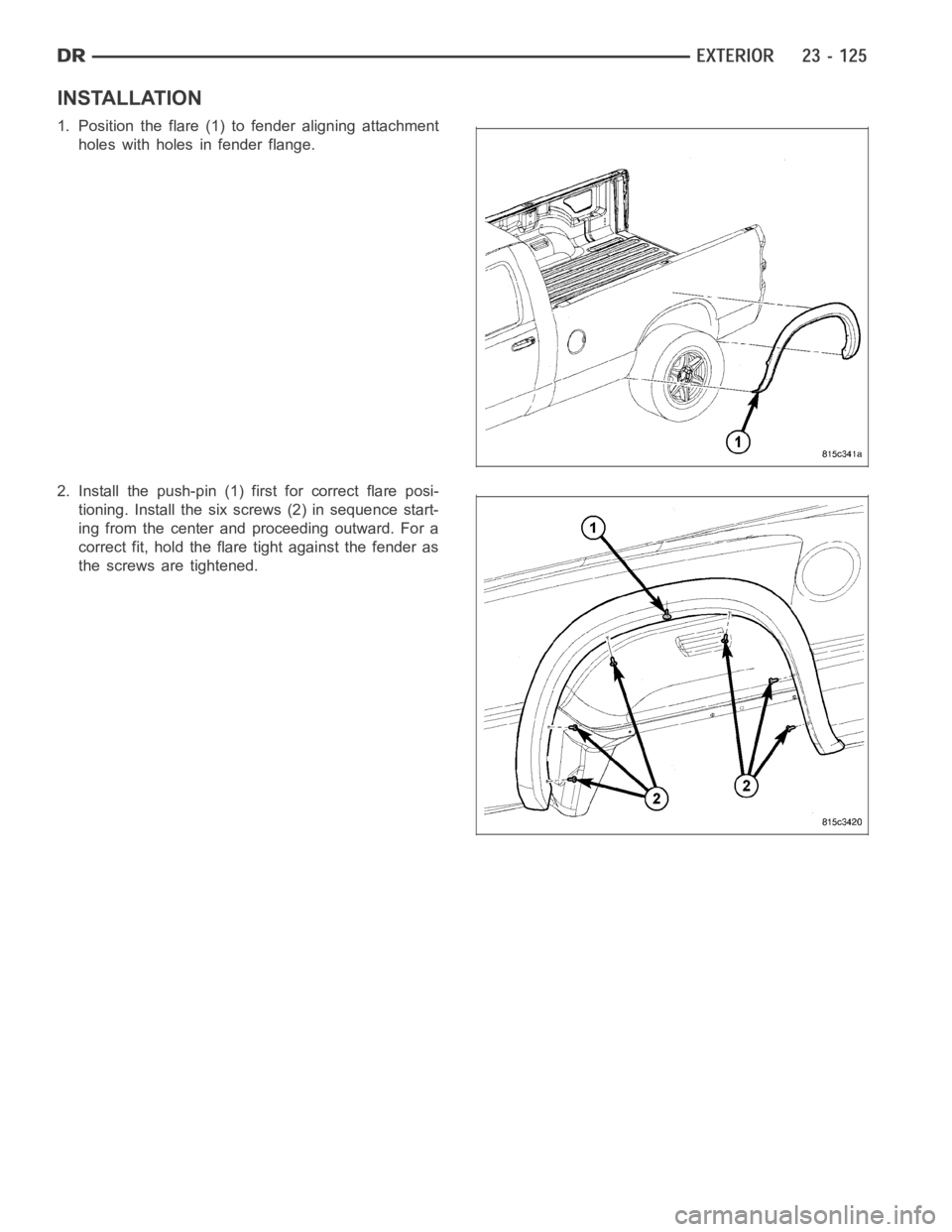
INSTALLATION
1. Position the flare (1) to fender aligning attachment
holes with holes in fender flange.
2. Install the push-pin (1) first for correct flare posi-
tioning. Install the six screws (2) in sequence start-
ing from the center and proceeding outward. For a
correct fit, hold the flare tight against the fender as
the screws are tightened.
Page 4463 of 5267
page page
BEZEL-HOOD SRT-10
REMOVAL ................................... 127
INSTALLATION .............................. 128
HINGE
REMOVAL ................................... 130
INSTALLATION .............................. 130
HOOD
REMOVAL ................................... 132
INSTALLATION .............................. 132
LATCH
REMOVAL ................................... 133INSTALLATION .............................. 133
LATCH RELEASE CABLE/HANDLE ASSEMBLY
REMOVAL
REMOVAL ................................ 134
INSTALLATION .............................. 134
LATCH STRIKER / SECONDARY CATCH
REMOVAL ................................... 135
INSTALLATION .............................. 135
SUPPORT CYLINDER
REMOVAL ................................... 136
INSTALLATION .............................. 137
Page 4464 of 5267
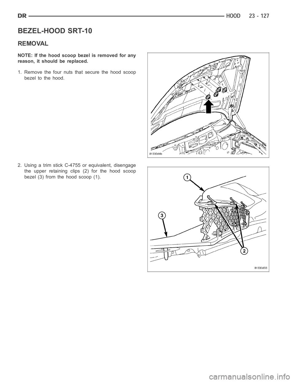
BEZEL-HOOD SRT-10
REMOVAL
NOTE: If the hood scoop bezel is removed for any
reason, it should be replaced.
1. Remove the four nuts that secure the hood scoop
bezel to the hood.
2. Using a trim stick C-4755 or equivalent, disengage
the upper retaining clips (2) for the hood scoop
bezel (3) from the hood scoop (1).
Page 4465 of 5267
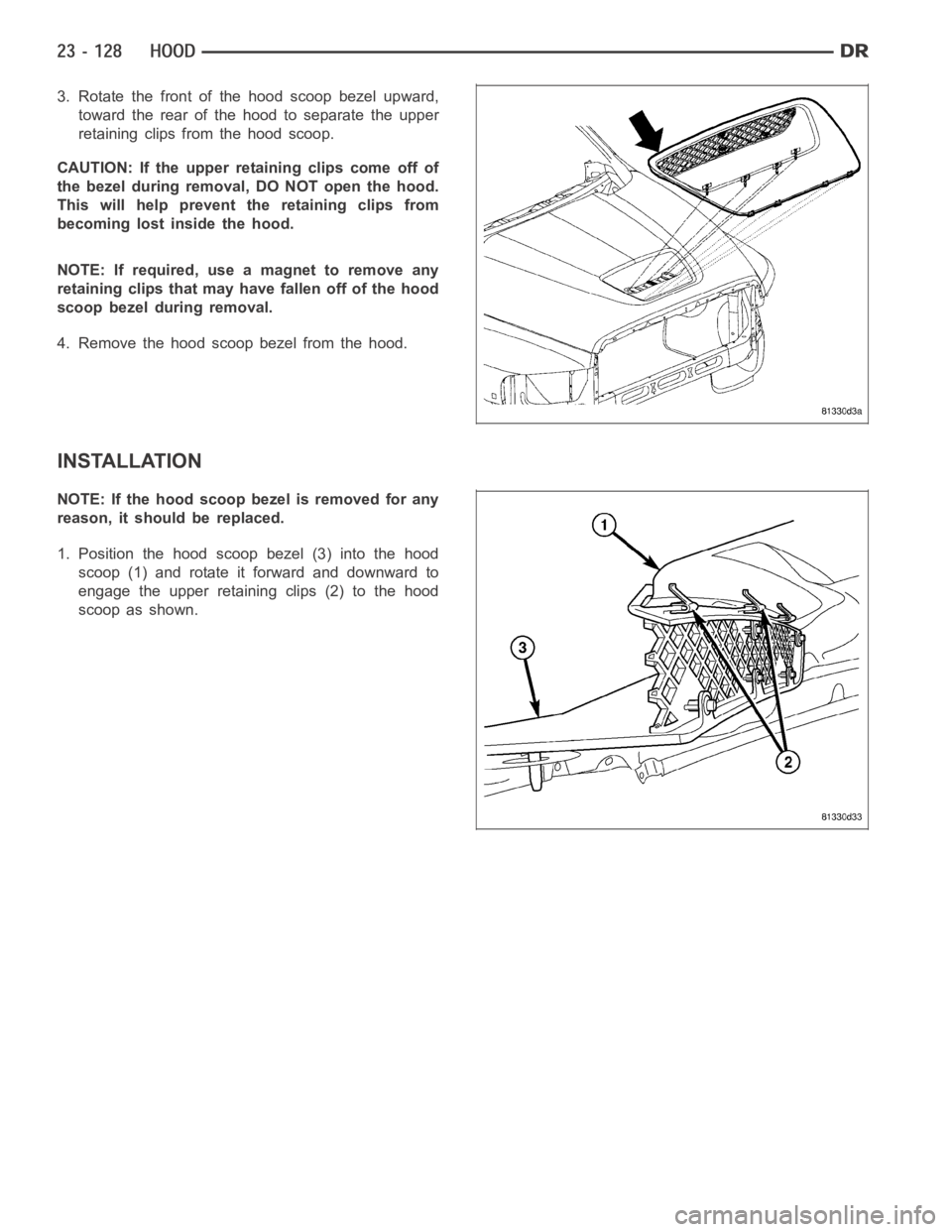
3. Rotate the front of the hood scoop bezel upward,
toward the rear of the hood to separate the upper
retaining clips from the hood scoop.
CAUTION: If the upper retaining clips come off of
the bezel during removal, DO NOT open the hood.
This will help prevent the retaining clips from
becoming lost inside the hood.
NOTE: If required, use a magnet to remove any
retaining clips that may have fallen off of the hood
scoop bezel during removal.
4. Remove the hood scoop bezel from the hood.
INSTALLATION
NOTE: If the hood scoop bezel is removed for any
reason, it should be replaced.
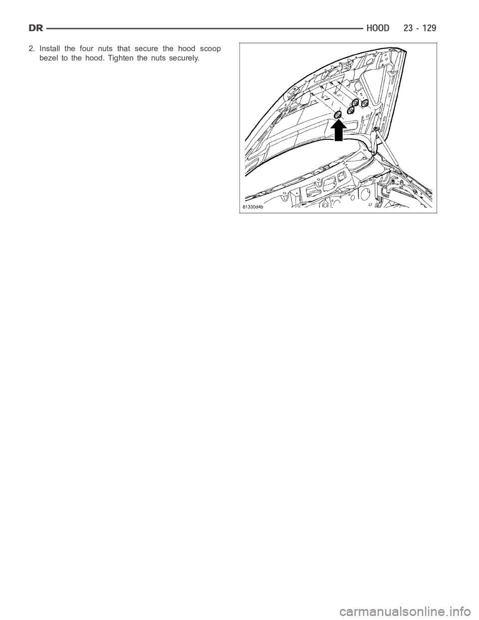
1. Position the hood scoop bezel (3) into the hood
scoop (1) and rotate it forward and downward to
engage the upper retaining clips (2) to the hood
scoop as shown.
Page 4466 of 5267
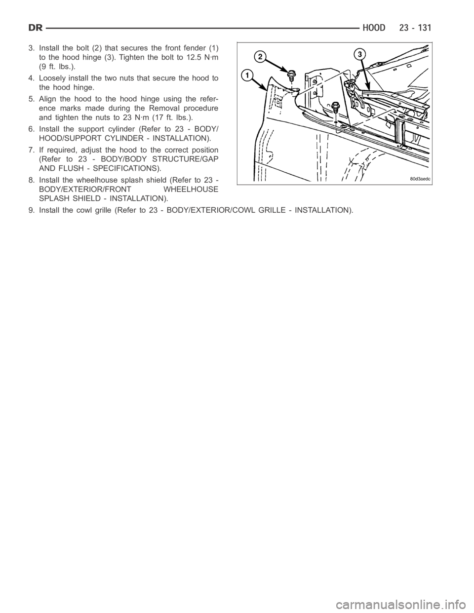
2. Install the four nuts that secure the hood scoop
bezel to the hood. Tighten the nuts securely.
Page 4467 of 5267
HINGE
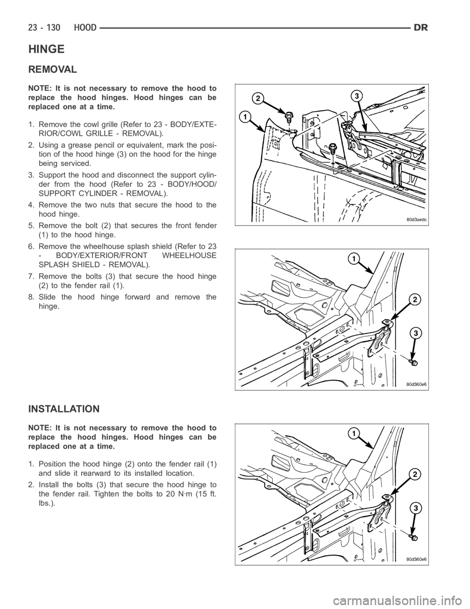
REMOVAL
NOTE: It is not necessary to remove the hood to
replace the hood hinges. Hood hinges can be
replaced one at a time.
1. Remove the cowl grille (Refer to 23 - BODY/EXTE-
RIOR/COWL GRILLE - REMOVAL).
2. Using a grease pencil or equivalent, mark the posi-
tion of the hood hinge (3) on the hood for the hinge
being serviced.
3. Support the hood and disconnect the support cylin-
der from the hood (Refer to 23 - BODY/HOOD/
SUPPORT CYLINDER - REMOVAL).
4. Remove the two nuts that secure the hood to the
hood hinge.
5. Remove the bolt (2) that secures the front fender
(1) to the hood hinge.
6. Remove the wheelhouse splash shield (Refer to 23
- BODY/EXTERIOR/FRONT WHEELHOUSE
SPLASH SHIELD - REMOVAL).
7. Remove the bolts (3) that secure the hood hinge
(2) to the fender rail (1).
8. Slide the hood hinge forward and remove the
hinge.
INSTALLATION
NOTE: It is not necessary to remove the hood to
replace the hood hinges. Hood hinges can be
replaced one at a time.
1. Position the hood hinge (2) onto the fender rail (1)
and slide it rearward to its installed location.
2. Install the bolts (3) that secure the hood hinge to
the fender rail. Tighten the bolts to 20 Nꞏm (15 ft.
lbs.).
Page 4468 of 5267
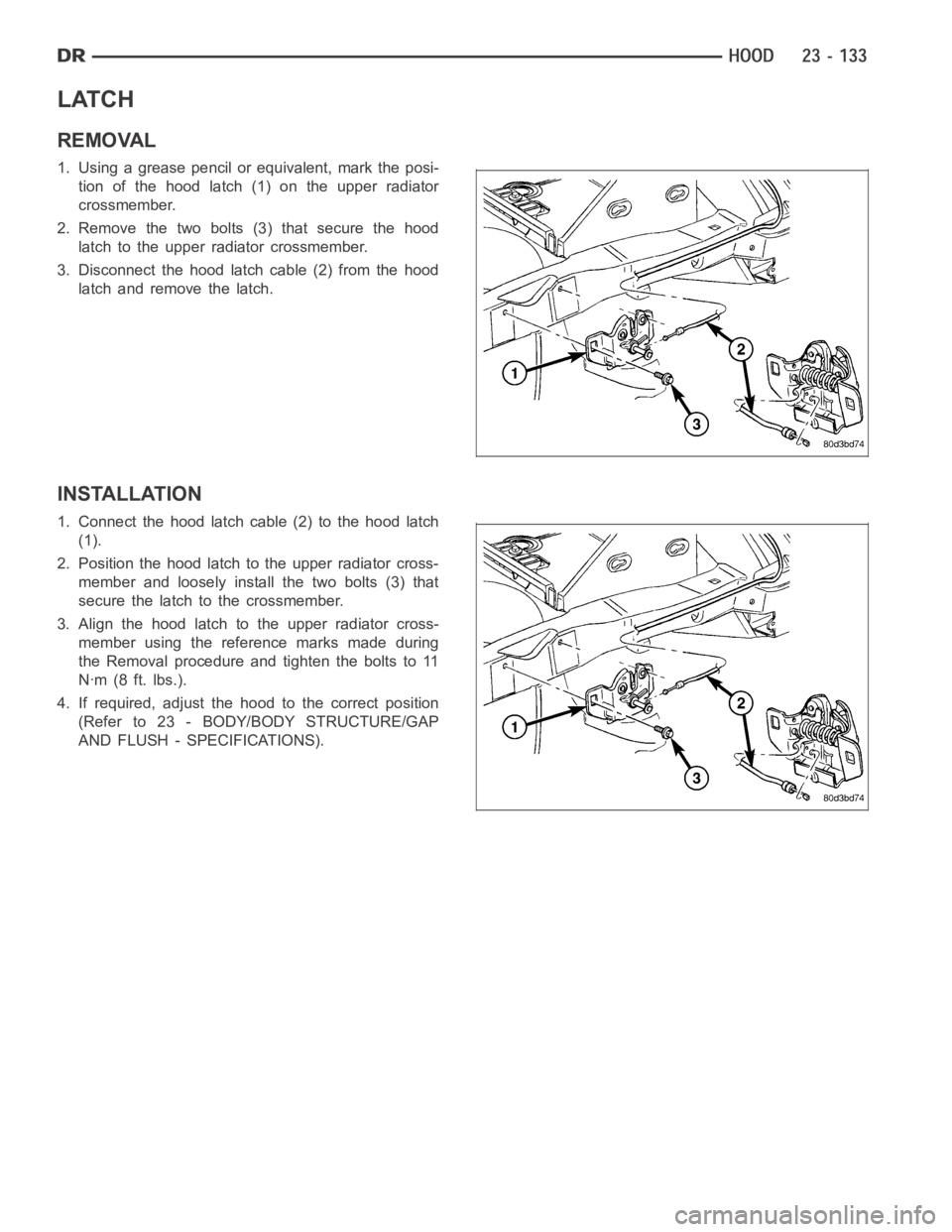
3. Install the bolt (2) that secures the front fender (1)
to the hood hinge (3). Tighten the bolt to 12.5 Nꞏm
(9 ft. lbs.).
4. Loosely install the two nuts that secure the hood to
the hood hinge.
5. Align the hood to the hood hinge using the refer-
ence marks made during the Removal procedure
and tighten the nuts to 23 Nꞏm (17 ft. lbs.).
6. Install the support cylinder (Refer to 23 - BODY/
HOOD/SUPPORT CYLINDER - INSTALLATION).
7. If required, adjust the hood to the correct position
(Refer to 23 - BODY/BODY STRUCTURE/GAP
AND FLUSH - SPECIFICATIONS).
8. Install the wheelhouse splash shield (Refer to 23 -
BODY/EXTERIOR/FRONT WHEELHOUSE
SPLASH SHIELD - INSTALLATION).
9. Install the cowl grille (Refer to 23 - BODY/EXTERIOR/COWL GRILLE - INSTALLATION).
Page 4469 of 5267
HOOD
REMOVAL
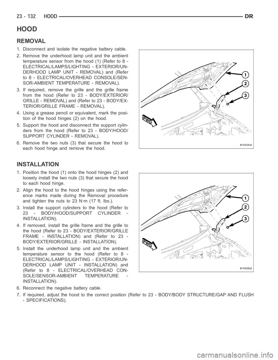
1. Disconnect and isolate the negative battery cable.
2. Remove the underhood lamp unit and the ambient
temperature sensor from the hood (1) (Refer to 8 -
ELECTRICAL/LAMPS/LIGHTING - EXTERIOR/UN-
DERHOOD LAMP UNIT - REMOVAL) and (Refer
to 8 - ELECTRICAL/OVERHEAD CONSOLE/SEN-
SOR-AMBIENT TEMPERATURE - REMOVAL).
3. If required, remove the grille and the grille frame
from the hood (Refer to 23 - BODY/EXTERIOR/
GRILLE - REMOVAL) and (Refer to 23 - BODY/EX-
TERIOR/GRILLE FRAME - REMOVAL).
4. Using a grease pencil or equivalent, mark the posi-
tion of the hood hinges (2) on the hood.
5. Support the hood and disconnect the support cylin-
ders from the hood (Refer to 23 - BODY/HOOD/
SUPPORT CYLINDER - REMOVAL).
6. Remove the two nuts (3) that secure the hood to
each hood hinge and remove the hood.
INSTALLATION
1. Position the hood (1) onto the hood hinges (2) and
loosely install the two nuts (3) that secure the hood
to each hood hinge.
2. Align the hood to the hood hinges using the refer-
ence marks made during the Removal procedure
and tighten the nuts to 23 Nꞏm (17 ft. lbs.).
3. Install the support cylinders to the hood (Refer to
23 - BODY/HOOD/SUPPORT CYLINDER -
INSTALLATION).
4. If removed, install the grille frame and the grille to
the hood (Refer to 23 - BODY/EXTERIOR/GRILLE
FRAME - INSTALLATION) and (Refer to 23 -
BODY/EXTERIOR/GRILLE - INSTALLATION).
5. Install the underhood lamp unit and the ambient
temperature sensor to the hood (Refer to 8 -
ELECTRICAL/LAMPS/LIGHTING - EXTERIOR/UN-
DERHOOD LAMP UNIT - INSTALLATION) and
(Refer to 8 - ELECTRICAL/OVERHEAD CON-
SOLE/SENSOR-AMBIENT TEMPERATURE -
INSTALLATION).
6. Reconnect the negative battery cable.
7. If required, adjust the hood to the correct position (Refer to 23 - BODY/BODY STRUCTURE/GAP AND FLUSH
- SPECIFICATIONS).
Page 4470 of 5267
LATCH
REMOVAL
1. Using a grease pencil or equivalent, mark the posi-
tion of the hood latch (1) on the upper radiator
crossmember.
2. Remove the two bolts (3) that secure the hood
latch to the upper radiator crossmember.
3. Disconnect the hood latch cable (2) from the hood
latch and remove the latch.
INSTALLATION
1. Connect the hood latch cable (2) to the hood latch
(1).
2. Position the hood latch to the upper radiator cross-
member and loosely install the two bolts (3) that
secure the latch to the crossmember.
3. Align the hood latch to the upper radiator cross-
member using the reference marks made during
the Removal procedure and tighten the bolts to 11
Nꞏm (8 ft. lbs.).
4. If required, adjust the hood to the correct position
(Refer to 23 - BODY/BODY STRUCTURE/GAP
AND FLUSH - SPECIFICATIONS).
Trending: spark plugs replace, center console, fuel, wiring, seats, spark plugs, warning light
