DODGE RAM SRT-10 2006 Service Repair Manual
RAM SRT-10 2006
DODGE
DODGE
https://www.carmanualsonline.info/img/12/56917/w960_56917-0.png
DODGE RAM SRT-10 2006 Service Repair Manual
Trending: diagram, brakes, ECO mode, ground clearance, height adjustment, brake, air suspension
Page 4531 of 5267
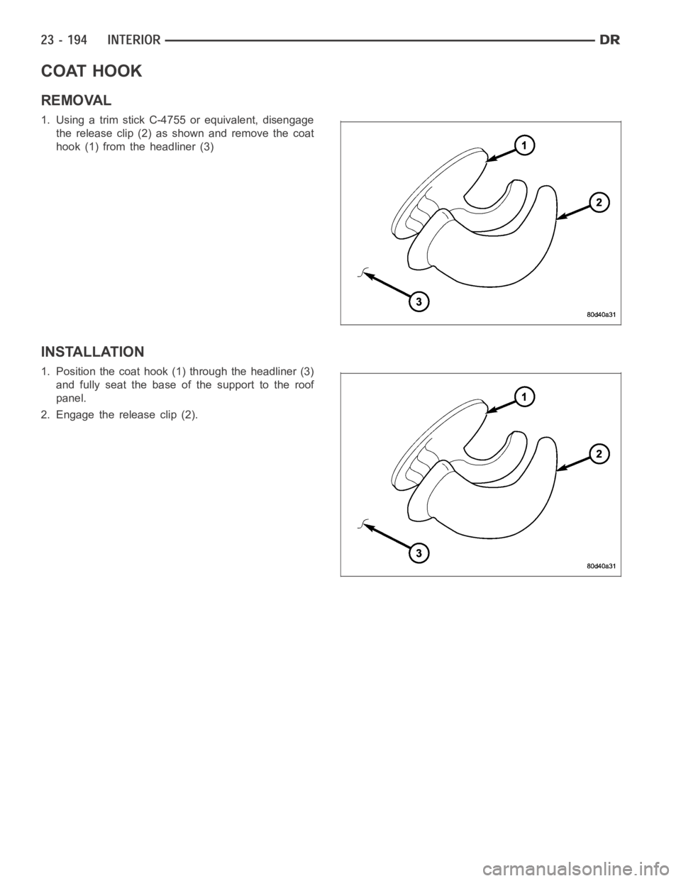
COAT HOOK
REMOVAL
1. Using a trim stick C-4755 or equivalent, disengage
the release clip (2) as shown and remove the coat
hook (1) from the headliner (3)
INSTALLATION
1. Position the coat hook (1) through the headliner (3)
and fully seat the base of the support to the roof
panel.
2. Engage the release clip (2).
Page 4532 of 5267
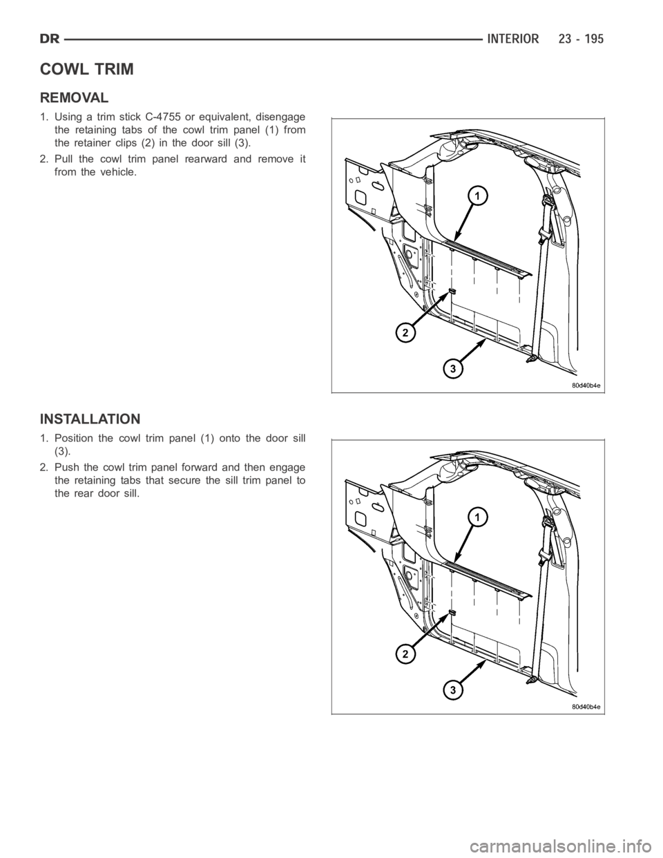
COWL TRIM
REMOVAL
1. Using a trim stick C-4755 or equivalent, disengage
the retaining tabs of the cowl trim panel (1) from
the retainer clips (2) in the door sill (3).
2. Pull the cowl trim panel rearward and remove it
from the vehicle.
INSTALLATION
1. Position the cowl trim panel (1) onto the door sill
(3).
2. Push the cowl trim panel forward and then engage
the retaining tabs that secure the sill trim panel to
the rear door sill.
Page 4533 of 5267
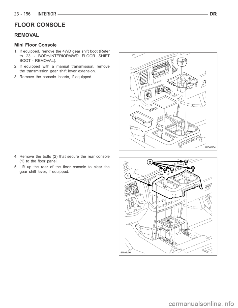
FLOOR CONSOLE
REMOVAL
Mini Floor Console
1. If equipped, remove the 4WD gear shift boot (Refer
to 23 - BODY/INTERIOR/4WD FLOOR SHIFT
BOOT - REMOVAL).
2. If equipped with a manual transmission, remove
the transmission gear shift lever extension.
3. Remove the console inserts, if equipped.
4. Remove the bolts (2) that secure the rear console
(1) to the floor panel.
5. Lift up the rear of the floor console to clear the
gear shift lever, if equipped.
Page 4534 of 5267
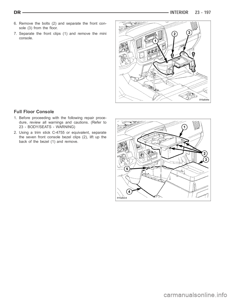
6. Remove the bolts (2) and separate the front con-
sole (3) from the floor.
7. Separate the front clips (1) and remove the mini
console.
Full Floor Console
1. Before proceeding with the following repair proce-
dure, review all warnings and cautions. (Refer to
23 - BODY/SEATS - WARNING)
2. Using a trim stick C-4755 or equivalent, separate
the seven front console bezel clips (2), lift up the
back of the bezel (1) and remove.
Page 4535 of 5267
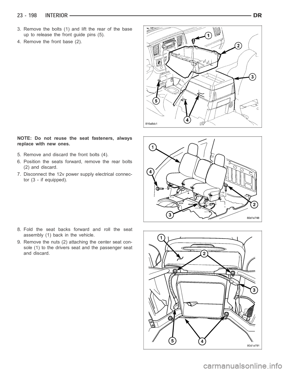
3. Remove the bolts (1) and lift the rear of the base
up to release the front guide pins (5).
4. Remove the front base (2).
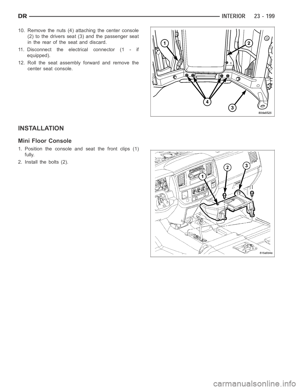
NOTE: Do not reuse the seat fasteners, always
replace with new ones.
5. Remove and discard the front bolts (4).
6. Position the seats forward, remove the rear bolts
(2) and discard.
7. Disconnect the 12v power supply electrical connec-
tor (3 - if equipped).
8. Fold the seat backs forward and roll the seat
assembly (1) back in the vehicle.
9. Remove the nuts (2) attaching the center seat con-
sole (1) to the drivers seat and the passenger seat
and discard.
Page 4536 of 5267
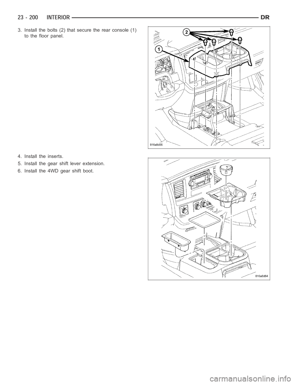
10. Remove the nuts (4) attaching the center console
(2) to the drivers seat (3) and the passenger seat
in the rear of the seat and discard.
11. Disconnect the electrical connector (1 - if
equipped).
12. Roll the seat assembly forward and remove the
center seat console.
INSTALLATION
Mini Floor Console
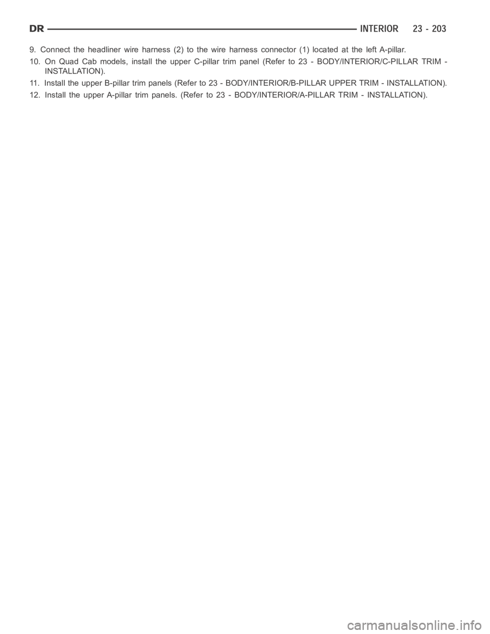
1. Position the console and seat the front clips (1)
fully.
2. Install the bolts (2).
Page 4537 of 5267
3. Install the bolts (2) that secure the rear console (1)
to the floor panel.
4. Install the inserts.
5. Install the gear shift lever extension.
6. Install the 4WD gear shift boot.
Page 4538 of 5267
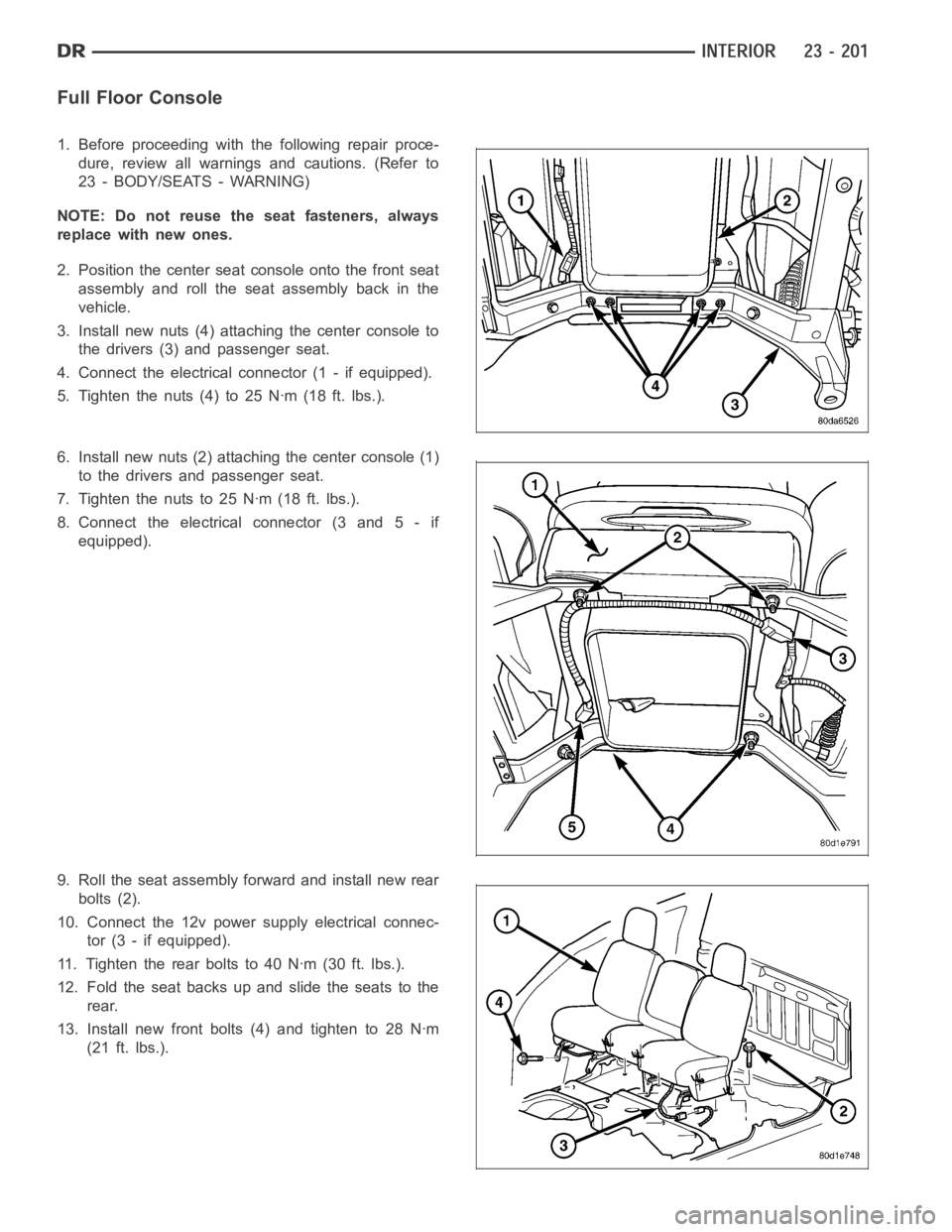
Full Floor Console
1. Before proceeding with the following repair proce-
dure, review all warnings and cautions. (Refer to
23 - BODY/SEATS - WARNING)
NOTE: Do not reuse the seat fasteners, always
replace with new ones.
2. Position the center seat console onto the front seat
assembly and roll the seat assembly back in the
vehicle.
3. Install new nuts (4) attaching the center console to
the drivers (3) and passenger seat.
4. Connect the electrical connector (1 - if equipped).
5. Tighten the nuts (4) to 25 Nꞏm (18 ft. lbs.).
6. Install new nuts (2) attaching the center console (1)
to the drivers and passenger seat.
7. Tightenthenutsto25Nꞏm(18ft.lbs.).
8. Connect the electrical connector (3 and 5 - if
equipped).
9. Roll the seat assembly forward and install new rear
bolts (2).
10. Connect the 12v power supply electrical connec-
tor (3 - if equipped).
11. Tighten the rear bolts to 40 Nꞏm (30 ft. lbs.).
12. Fold the seat backs up and slide the seats to the
rear.
13. Install new front bolts (4) and tighten to 28 Nꞏm
(21 ft. lbs.).
Page 4539 of 5267
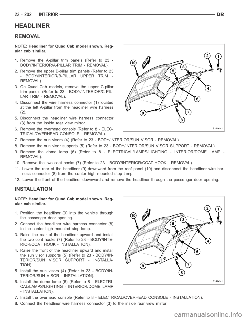
HEADLINER
REMOVAL
NOTE: Headliner for Quad Cab model shown. Reg-
ular cab similar.
1. Remove the A-pillar trim panels (Refer to 23 -
BODY/INTERIOR/A-PILLAR TRIM - REMOVAL).
2. Remove the upper B-pillar trim panels (Refer to 23
- BODY/INTERIOR/B-PILLAR UPPER TRIM -
REMOVAL).
3. On Quad Cab models, remove the upper C-pillar
trim panels (Refer to 23 - BODY/INTERIOR/C-PIL-
LAR TRIM - REMOVAL).
4. Disconnect the wire harness connector (1) located
at the left A-pillar from the headliner wire harness
(2).
5. Disconnect the headliner wire harness connector
(3) from the inside rear view mirror.
6. Remove the overhead console (Refer to 8 - ELEC-
TRICAL/OVERHEAD CONSOLE - REMOVAL).
7. Remove the sun visors (4) (Refer to 23 - BODY/INTERIOR/SUN VISOR - REMOVAL).
8. Remove the sun visor supports (5) (Refer to 23 - BODY/INTERIOR/SUN VISORSUPPORT - REMOVAL).
9. Remove the dome lamp (6) (Refer to 8 -ELECTRICAL/LAMPS/LIGHTING - INTERIOR/DOME LAMP -
REMOVAL).
10. Remove the two coat hooks (7) (Refer to 23 - BODY/INTERIOR/COAT HOOK - REMOVAL).
11. Lower the rear of the headliner (9) downward from the roof panel (10) anddisconnect the headliner wire har-
ness connector (8) from the center high mounted stop lamp.
12. Lower the front of the headliner downward and remove the headliner through the passenger door opening.
INSTALLATION
NOTE: Headliner for Quad Cab model shown. Reg-
ular cab similar.
1. Position the headliner (9) into the vehicle through
the passenger door opening.
2. Connect the headliner wire harness connector (8)
to the center high mounted stop lamp.
3. Raise the rear of the headliner upward and install
the two coat hooks (7) (Refer to 23 - BODY/INTE-
RIOR/COAT HOOK - INSTALLATION).
4. Raise the front of the headliner upward and install
the sun visor supports (5) (Refer to 23 - BODY/IN-
TERIOR/SUN VISOR SUPPORT - INSTALLA-
TION).
5. Install the sun visors (4) (Refer to 23 - BODY/IN-
TERIOR/SUN VISOR - INSTALLATION).
6. Install the dome lamp (6) (Refer to 8 - ELECTRI-
CAL/LAMPS/LIGHTING - INTERIOR/DOME LAMP
- INSTALLATION).
7. Install the overhead console (Refer to 8 - ELECTRICAL/OVERHEAD CONSOLE-INSTALLATION).
8. Connect the headliner wire harness connector (3) to the inside rear viewmirror
Page 4540 of 5267
9. Connect the headliner wire harness (2) to the wire harness connector (1)located at the left A-pillar.
10. On Quad Cab models, install the upper C-pillar trim panel (Refer to 23 - BODY/INTERIOR/C-PILLAR TRIM -
INSTALLATION).
11. Install the upper B-pillar trim panels (Refer to 23 - BODY/INTERIOR/B-PILLAR UPPER TRIM - INSTALLATION).
12. Install the upper A-pillar trim panels. (Refer to 23 - BODY/INTERIOR/A-PILLAR TRIM - INSTALLATION).
Trending: fuel pump, hood release, audio, park assist, center console, sunroof, automatic transmission fluid
