DODGE RAM SRT-10 2006 Service Repair Manual
RAM SRT-10 2006
DODGE
DODGE
https://www.carmanualsonline.info/img/12/56917/w960_56917-0.png
DODGE RAM SRT-10 2006 Service Repair Manual
Trending: oil pressure, ECU, spare tire location, width, ignition, instrument cluster, clock
Page 4541 of 5267
LOAD FLOOR
REMOVAL
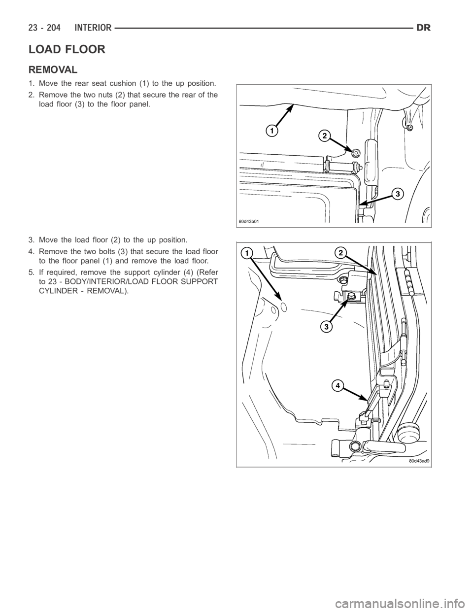
1. Move the rear seat cushion (1) to the up position.
2. Remove the two nuts (2) that secure the rear of the
load floor (3) to the floor panel.
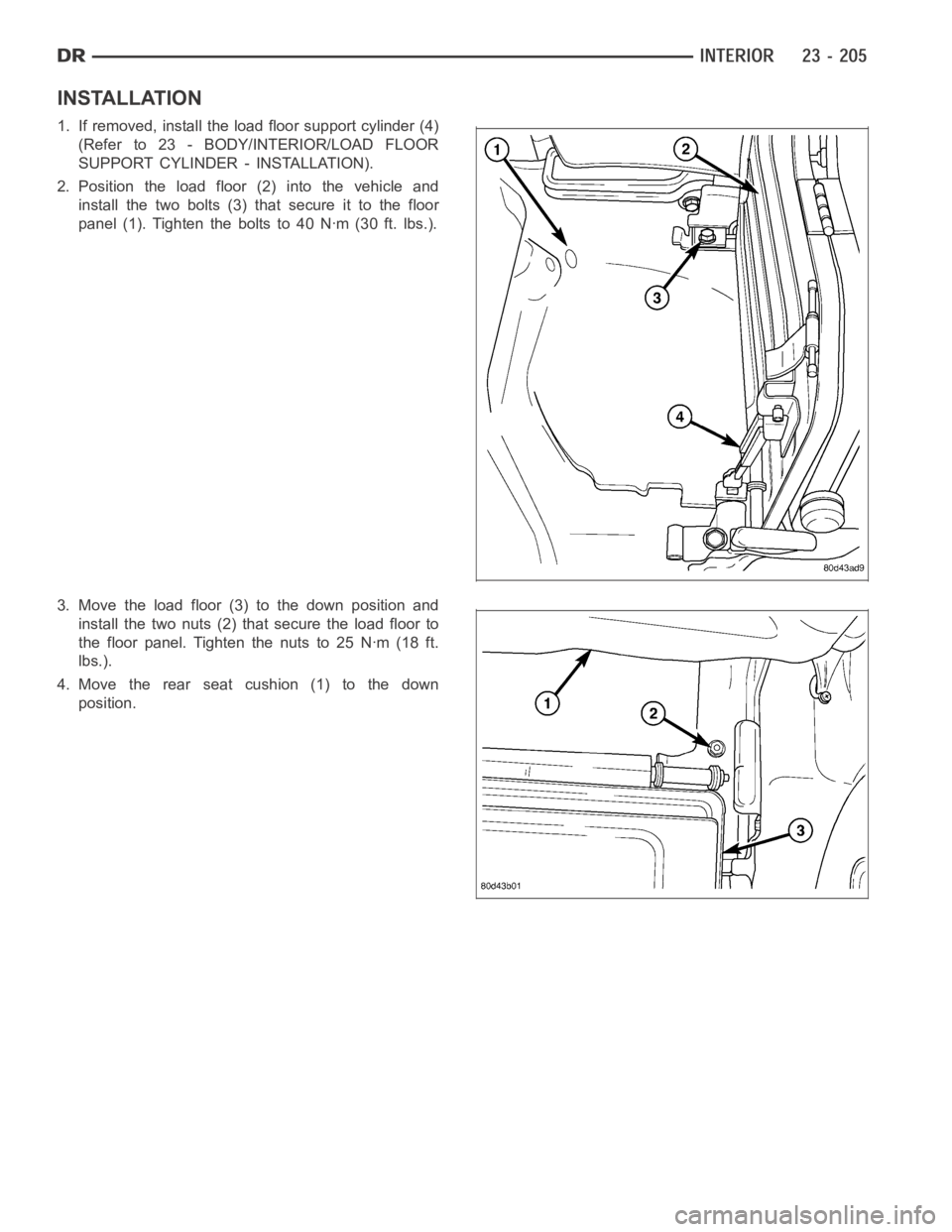
3. Move the load floor (2) to the up position.
4. Remove the two bolts (3) that secure the load floor
to the floor panel (1) and remove the load floor.
5. If required, remove the support cylinder (4) (Refer
to 23 - BODY/INTERIOR/LOAD FLOOR SUPPORT
CYLINDER - REMOVAL).
Page 4542 of 5267
INSTALLATION
1. If removed, install the load floor support cylinder (4)
(Refer to 23 - BODY/INTERIOR/LOAD FLOOR
SUPPORT CYLINDER - INSTALLATION).
2. Position the load floor (2) into the vehicle and
install the two bolts (3) that secure it to the floor
panel (1). Tighten the bolts to 40 Nꞏm (30 ft. lbs.).
3. Move the load floor (3) to the down position and
install the two nuts (2) that secure the load floor to
the floor panel. Tighten the nuts to 25 Nꞏm (18 ft.
lbs.).
4. Move the rear seat cushion (1) to the down
position.
Page 4543 of 5267
REAR CAB BACK PANEL TRIM
REMOVAL
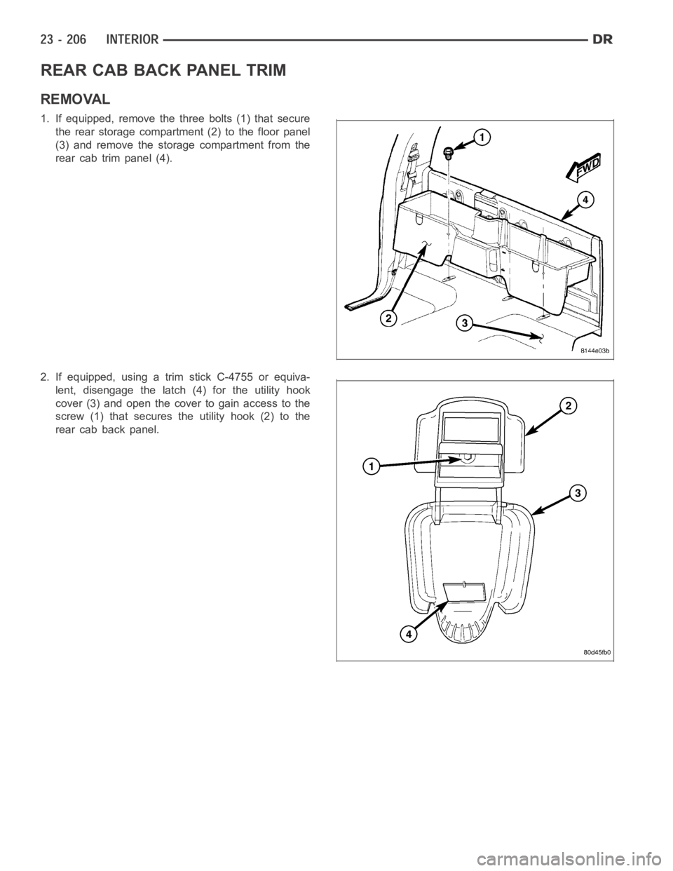
1. If equipped, remove the three bolts (1) that secure
the rear storage compartment (2) to the floor panel
(3) and remove the storage compartment from the
rear cab trim panel (4).
2. If equipped, using a trim stick C-4755 or equiva-
lent, disengage the latch (4) for the utility hook
cover (3) and open the cover to gain access to the
screw (1) that secures the utility hook (2) to the
rear cab back panel.
Page 4544 of 5267
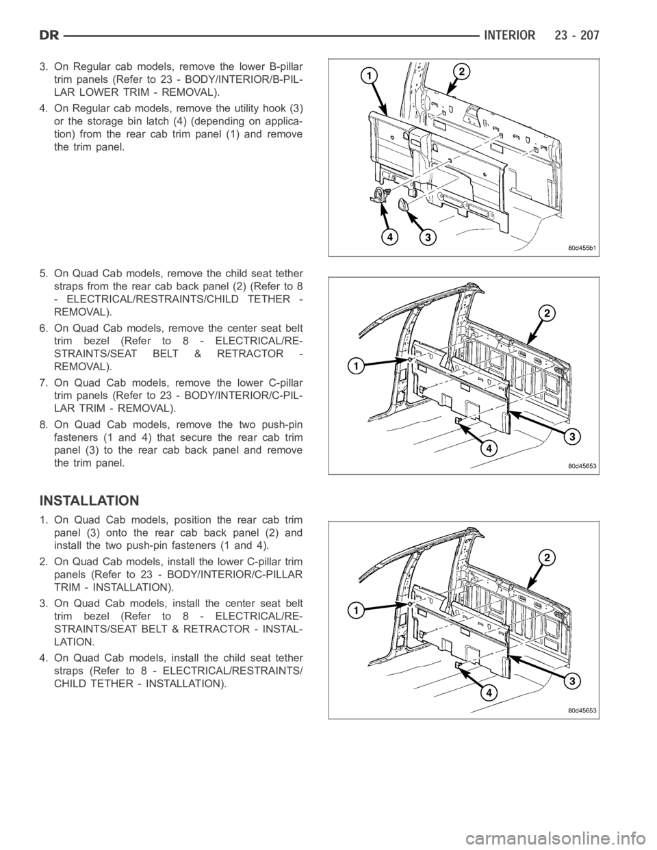
3. On Regular cab models, remove the lower B-pillar
trim panels (Refer to 23 - BODY/INTERIOR/B-PIL-
LAR LOWER TRIM - REMOVAL).
4. On Regular cab models, remove the utility hook (3)
or the storage bin latch (4) (depending on applica-
tion) from the rear cab trim panel (1) and remove
the trim panel.
5. On Quad Cab models, remove the child seat tether
straps from the rear cab back panel (2) (Refer to 8
- ELECTRICAL/RESTRAINTS/CHILD TETHER -
REMOVAL).
6. On Quad Cab models, remove the center seat belt
trim bezel (Refer to 8 - ELECTRICAL/RE-
STRAINTS/SEAT BELT & RETRACTOR -
REMOVAL).
7. On Quad Cab models, remove the lower C-pillar
trim panels (Refer to 23 - BODY/INTERIOR/C-PIL-
LAR TRIM - REMOVAL).
8. On Quad Cab models, remove the two push-pin
fasteners (1 and 4) that secure the rear cab trim
panel (3) to the rear cab back panel and remove
the trim panel.
INSTALLATION
1. On Quad Cab models, position the rear cab trim
panel (3) onto the rear cab back panel (2) and
install the two push-pin fasteners (1 and 4).
2. On Quad Cab models, install the lower C-pillar trim
panels (Refer to 23 - BODY/INTERIOR/C-PILLAR
TRIM - INSTALLATION).
3. On Quad Cab models, install the center seat belt
trim bezel (Refer to 8 - ELECTRICAL/RE-
STRAINTS/SEAT BELT & RETRACTOR - INSTAL-
LATION.
4. On Quad Cab models, install the child seat tether
straps (Refer to 8 - ELECTRICAL/RESTRAINTS/
CHILD TETHER - INSTALLATION).
Page 4545 of 5267
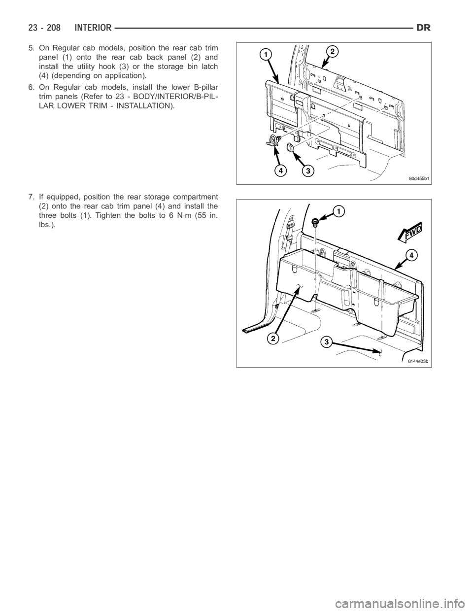
5. On Regular cab models, position the rear cab trim
panel (1) onto the rear cab back panel (2) and
install the utility hook (3) or the storage bin latch
(4) (depending on application).
6. On Regular cab models, install the lower B-pillar
trim panels (Refer to 23 - BODY/INTERIOR/B-PIL-
LAR LOWER TRIM - INSTALLATION).
7. If equipped, position the rear storage compartment
(2) onto the rear cab trim panel (4) and install the
threebolts(1).Tightentheboltsto6Nꞏm(55in.
lbs.).
Page 4546 of 5267
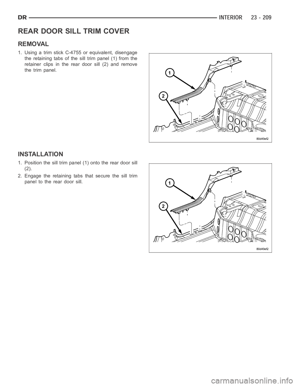
REAR DOOR SILL TRIM COVER
REMOVAL
1. Using a trim stick C-4755 or equivalent, disengage
the retaining tabs of the sill trim panel (1) from the
retainer clips in the rear door sill (2) and remove
the trim panel.
INSTALLATION
1. Position the sill trim panel (1) onto the rear door sill
(2).
2. Engage the retaining tabs that secure the sill trim
panel to the rear door sill.
Page 4547 of 5267
REAR VIEW MIRROR
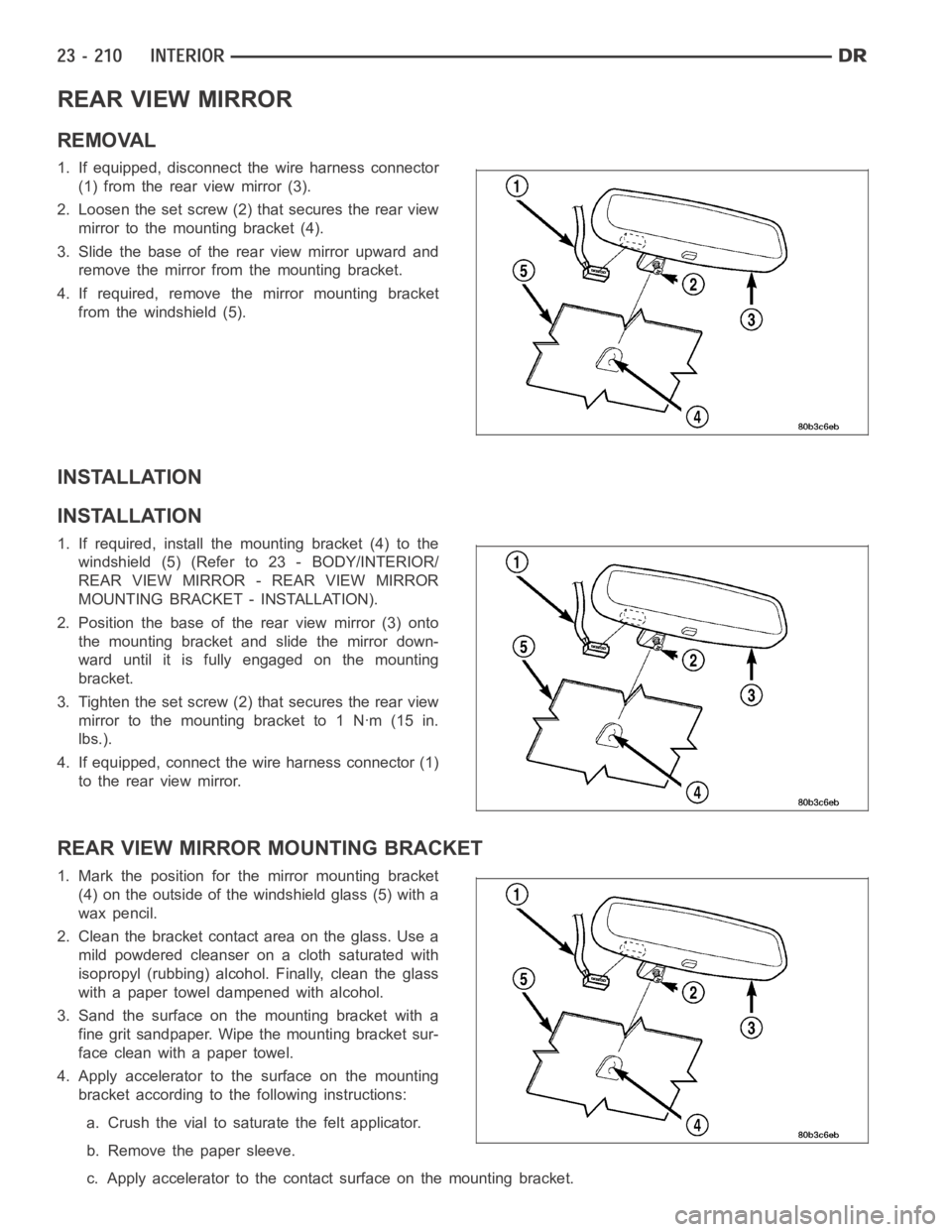
REMOVAL
1. If equipped, disconnect the wire harness connector
(1) from the rear view mirror (3).
2. Loosen the set screw (2) that secures the rear view
mirror to the mounting bracket (4).
3. Slide the base of the rear view mirror upward and
remove the mirror from the mounting bracket.
4. If required, remove the mirror mounting bracket
from the windshield (5).
INSTALLATION
INSTALLATION
1. If required, install the mounting bracket (4) to the
windshield (5) (Refer to 23 - BODY/INTERIOR/
REAR VIEW MIRROR - REAR VIEW MIRROR
MOUNTING BRACKET - INSTALLATION).
2. Position the base of the rear view mirror (3) onto
the mounting bracket and slide the mirror down-
ward until it is fully engaged on the mounting
bracket.
3. Tighten the set screw (2) that secures the rear view
mirrortothemountingbracketto1Nꞏm(15in.
lbs.).
4. If equipped, connect the wire harness connector (1)
to the rear view mirror.
REAR VIEW MIRROR MOUNTING BRACKET
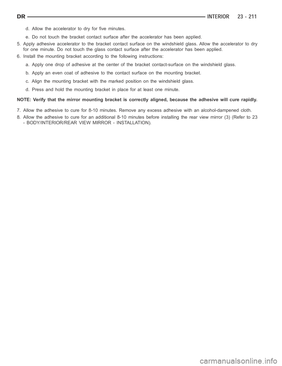
1.Markthepositionforthemirrormountingbracket
(4) on the outside of the windshield glass (5) with a
wax pencil.
2. Clean the bracket contact area on the glass. Use a
mild powdered cleanser on a cloth saturated with
isopropyl (rubbing) alcohol. Finally, clean the glass
with a paper towel dampened with alcohol.
3. Sand the surface on the mounting bracket with a
fine grit sandpaper. Wipe the mounting bracket sur-
face clean with a paper towel.
4. Apply accelerator to the surface on the mounting
bracket according to the following instructions:
a. Crush the vial to saturate the felt applicator.
b. Remove the paper sleeve.
c. Apply accelerator to the contact surface on the mounting bracket.
Page 4548 of 5267
d. Allow the accelerator to dry for five minutes.
e. Do not touch the bracket contact surface after the accelerator has been applied.
5. Apply adhesive accelerator to the bracket contact surface on the windshield glass. Allow the accelerator to dry
for one minute. Do not touch the glass contact surface after the accelerator has been applied.
6. Install the mounting bracket according to the following instructions:
a. Apply one drop of adhesive at the center of the bracket contact-surface on the windshield glass.
b. Apply an even coat of adhesive to the contact surface on the mounting bracket.
c. Align the mounting bracket with the marked position on the windshield glass.
d. Press and hold the mounting bracket in place for at least one minute.
NOTE: Verify that the mirror mounting bracket is correctly aligned, because the adhesive will cure rapidly.
7. Allow the adhesive to cure for 8-10 minutes. Remove any excess adhesive with an alcohol-dampened cloth.
8. Allow the adhesive to cure for an additional 8-10 minutes before installing the rear view mirror (3) (Refer to 23
- BODY/INTERIOR/REAR VIEW MIRROR - INSTALLATION).
Page 4549 of 5267
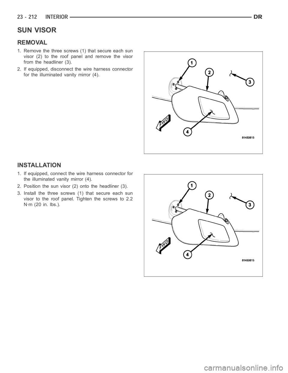
SUN VISOR
REMOVAL
1. Remove the three screws (1) that secure each sun
visor (2) to the roof panel and remove the visor
from the headliner (3).
2. If equipped, disconnect the wire harness connector
for the illuminated vanity mirror (4).
INSTALLATION
1. If equipped, connect the wire harness connector for
the illuminated vanity mirror (4).
2. Position the sun visor (2) onto the headliner (3).
3. Install the three screws (1) that secure each sun
visor to the roof panel. Tighten the screws to 2.2
Nꞏm (20 in. lbs.).
Page 4550 of 5267
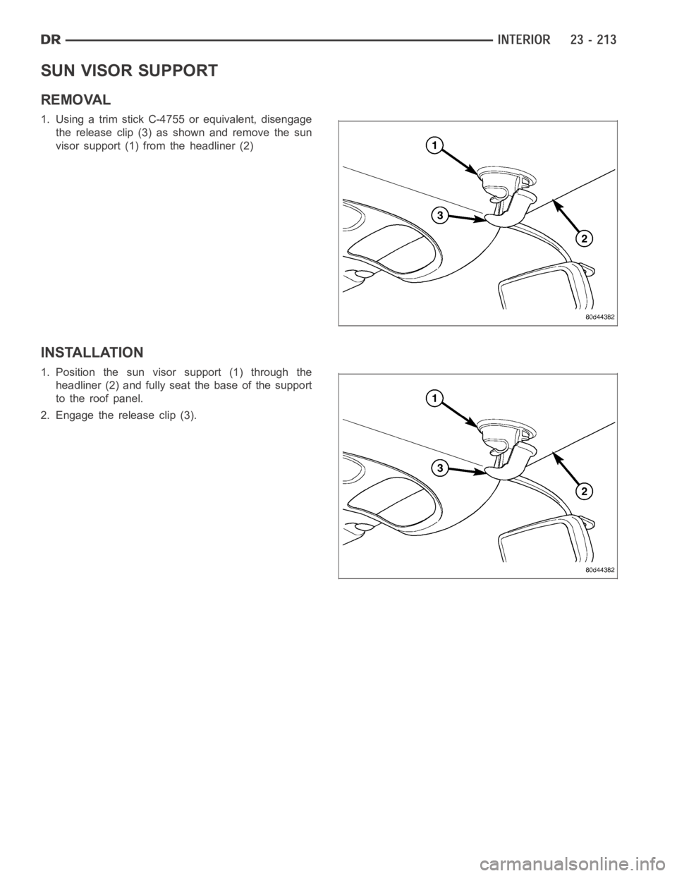
SUN VISOR SUPPORT
REMOVAL
1. Using a trim stick C-4755 or equivalent, disengage
the release clip (3) as shown and remove the sun
visor support (1) from the headliner (2)
INSTALLATION
1. Position the sun visor support (1) through the
headliner (2) and fully seat the base of the support
to the roof panel.
2. Engage the release clip (3).
Trending: oil dipstick, parking brake, roof, ad blue, cruise control, Fuel injector removal, radio antenna
