DODGE RAM SRT-10 2006 Service Repair Manual
RAM SRT-10 2006
DODGE
DODGE
https://www.carmanualsonline.info/img/12/56917/w960_56917-0.png
DODGE RAM SRT-10 2006 Service Repair Manual
Trending: clock setting, spark plugs replace, roof, turn signal, phone, lug pattern, diagram
Page 4571 of 5267
CENTER SEAT CUSHION COVER
REMOVAL
1. Remove the center seat cushion or underseat storage bin lid. (Refer to 23- BODY/SEATS/CENTER SEAT
CUSHION/UNDERSEAT STORAGE BIN LID - REMOVAL)
2. Disconnect the zip strips and remove the cover from the cushion.
INSTALLATION
1. Install the cover over the center seat cushion and connect the zip strips.
2. Install the center seat cushion or under seat storage bin lid. (Refer to 23 - BODY/SEATS/CENTER SEAT CUSH-
ION/UNDER SEAT STORAGE BIN LID - INSTALLATION)
Page 4572 of 5267
HEADREST
REMOVAL
1. Raise the headrest.
2. Press the headrest release button and remove the headrest.
INSTALLATION
1. Position the headrest.
2. Press the release button and install the headrest.
Page 4573 of 5267
HEADREST SLEEVE
REMOVAL
1. Remove the headrest. (Refer to 23 - BODY/SEATS/HEADREST - REMOVAL)
2. Grasp the sleeves and pull up and out of the seat back to remove.
INSTALLATION
1. Position each headrest sleeve into correct seat back hole and press intoplace fully.
2. Install the headrest. (Refer to 23 - BODY/SEATS/HEADREST - INSTALLATION)
Page 4574 of 5267
SEAT - FRONT
REMOVAL
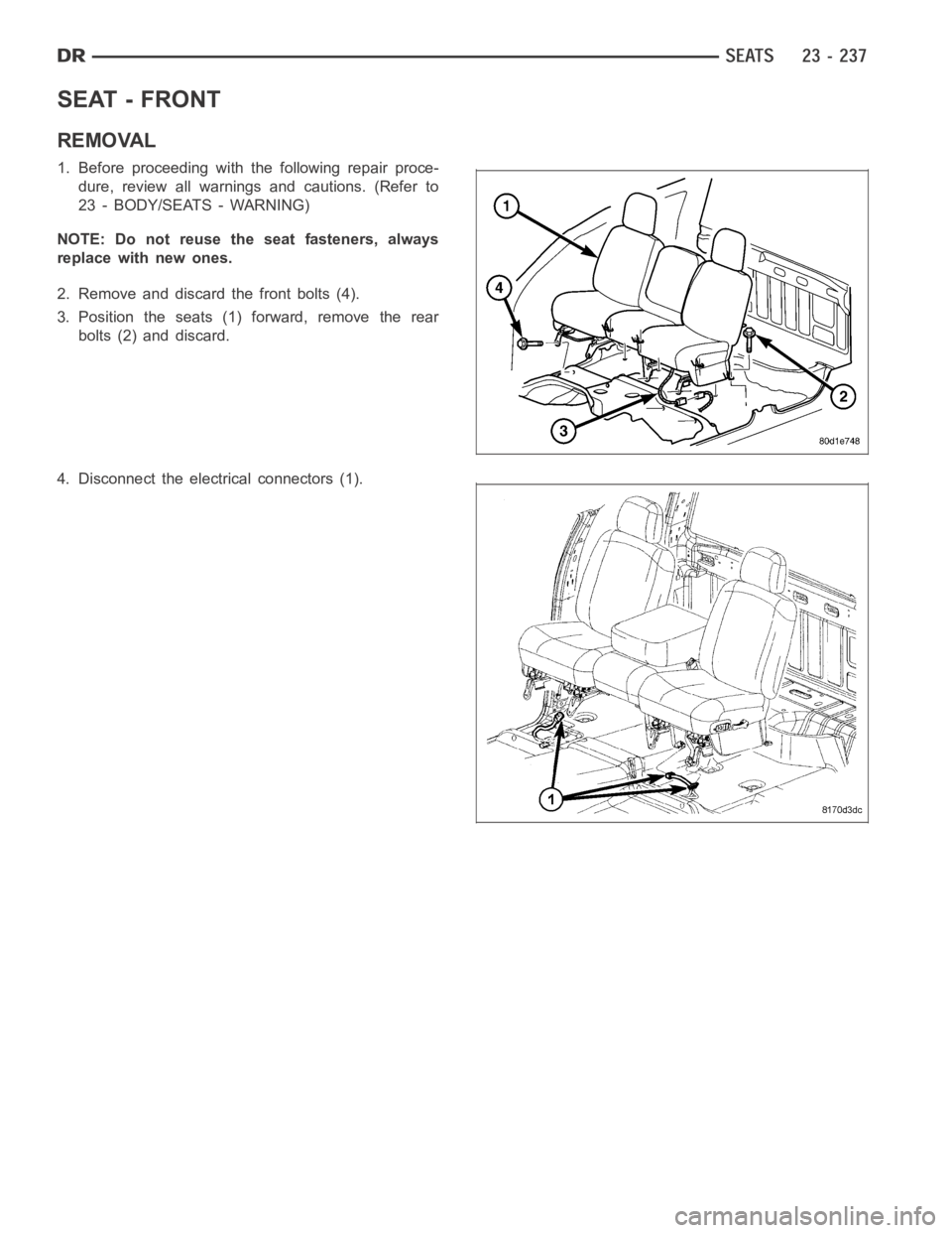
1. Before proceeding with the following repair proce-
dure, review all warnings and cautions. (Refer to
23 - BODY/SEATS - WARNING)
NOTE: Do not reuse the seat fasteners, always
replace with new ones.
2. Remove and discard the front bolts (4).
3. Position the seats (1) forward, remove the rear
bolts (2) and discard.
4. Disconnect the electrical connectors (1).
Page 4575 of 5267
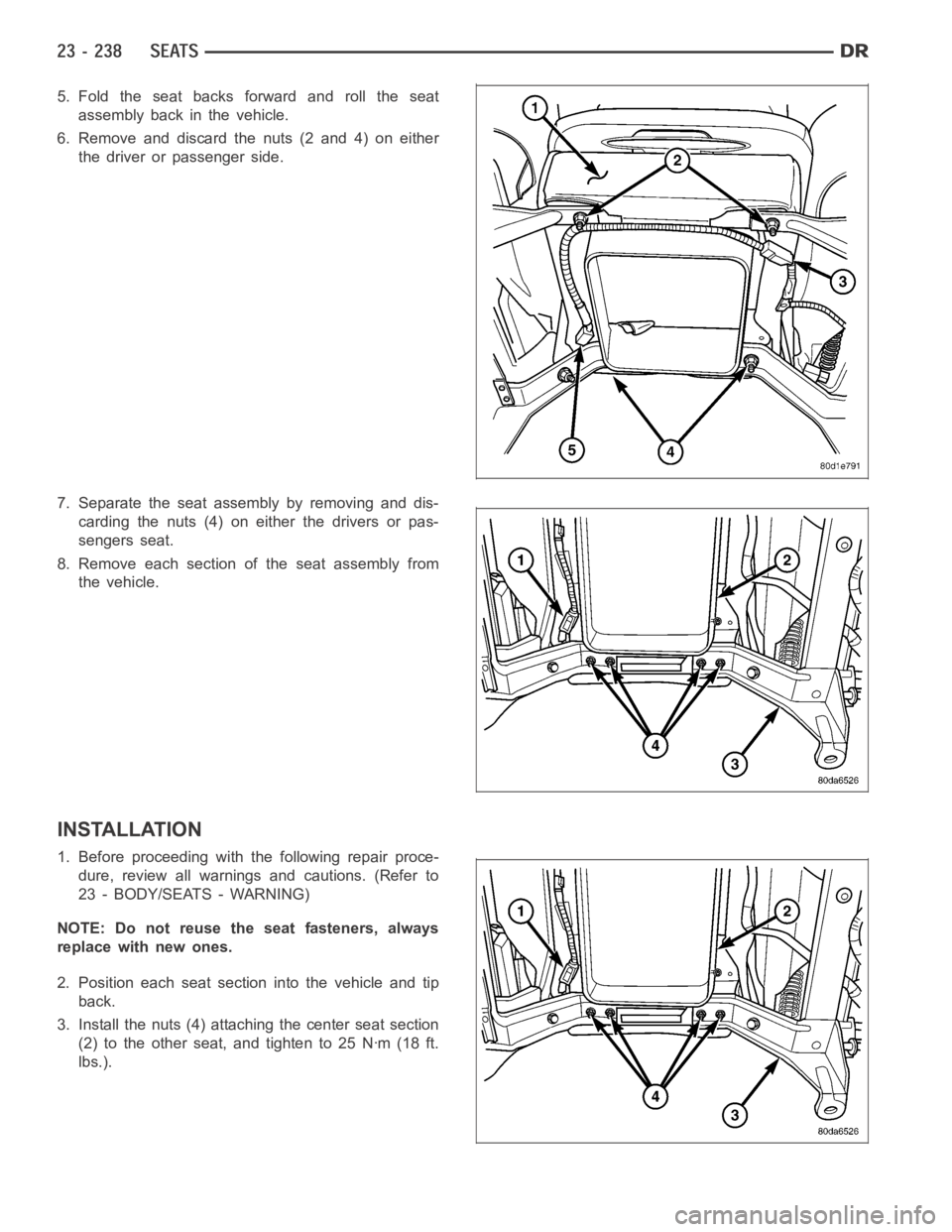
5. Fold the seat backs forward and roll the seat
assembly back in the vehicle.
6. Remove and discard the nuts (2 and 4) on either
the driver or passenger side.
7. Separate the seat assembly by removing and dis-
carding the nuts (4) on either the drivers or pas-
sengers seat.
8. Remove each section of the seat assembly from
the vehicle.
INSTALLATION
1. Before proceeding with the following repair proce-
dure, review all warnings and cautions. (Refer to
23 - BODY/SEATS - WARNING)
NOTE: Do not reuse the seat fasteners, always
replace with new ones.
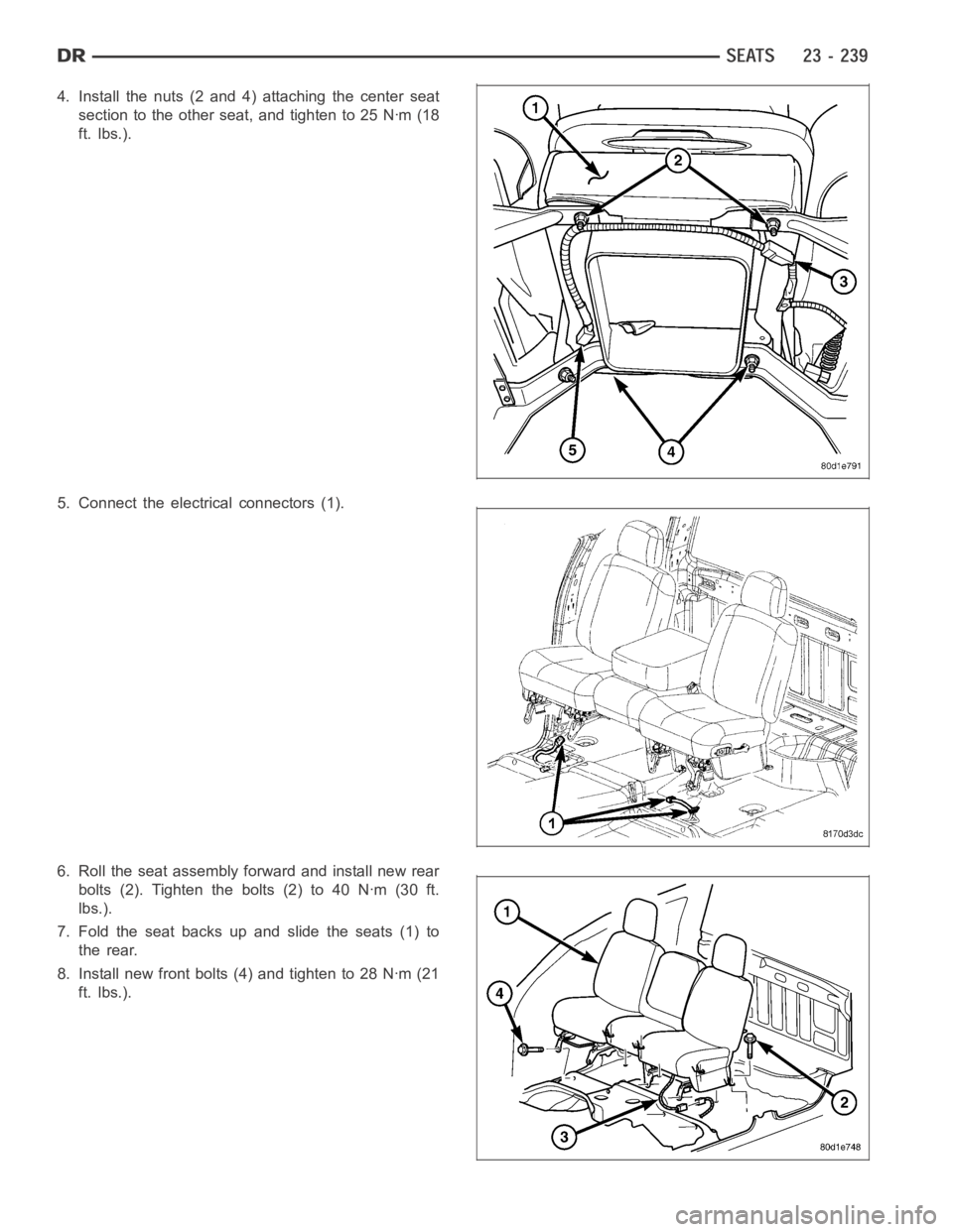
2. Position each seat section into the vehicle and tip
back.
3. Install the nuts (4) attaching the center seat section
(2) to the other seat, and tighten to 25 Nꞏm (18 ft.
lbs.).
Page 4576 of 5267
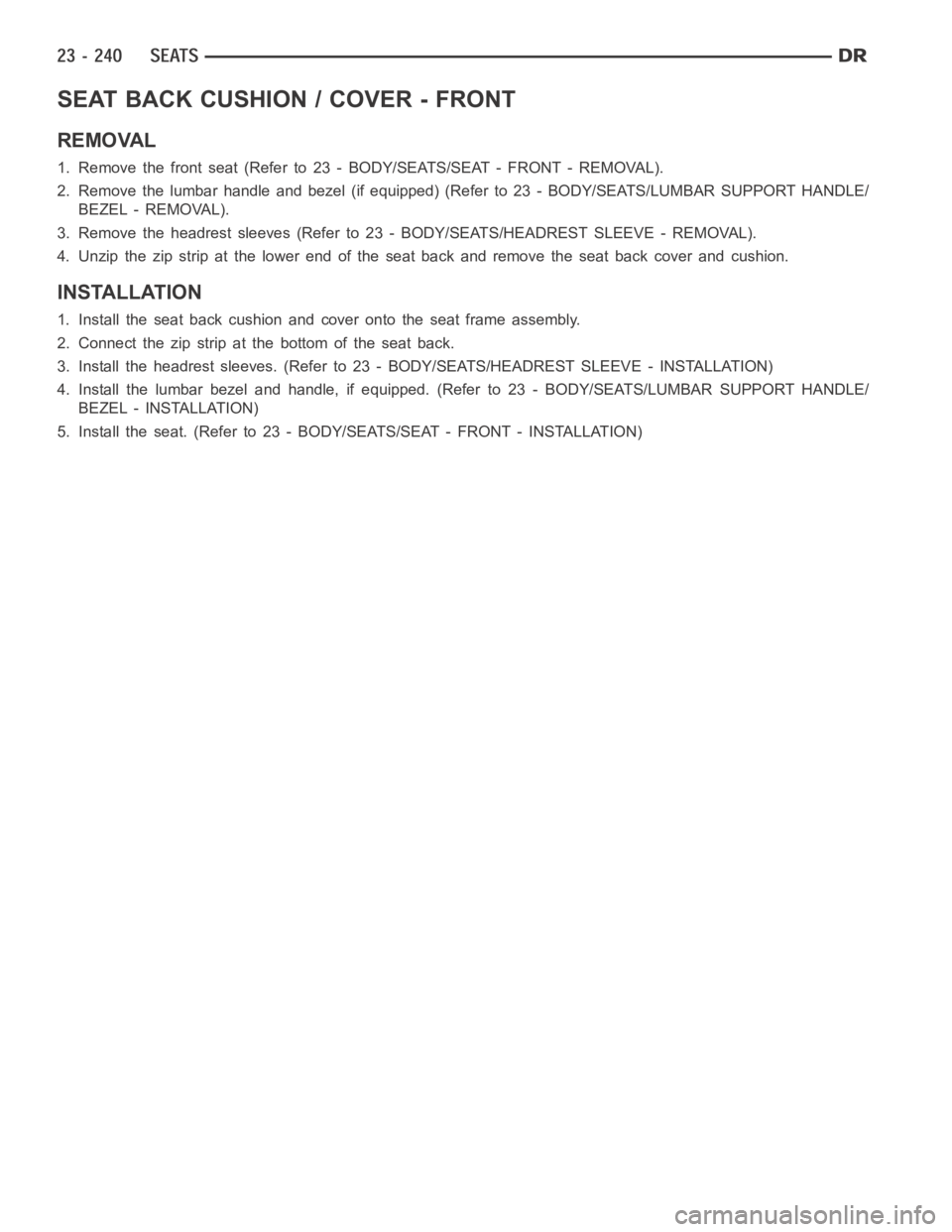
4. Install the nuts (2 and 4) attaching the center seat
section to the other seat, and tighten to 25 Nꞏm (18
ft. lbs.).
5. Connect the electrical connectors (1).
6. Roll the seat assembly forward and install new rear
bolts (2). Tighten the bolts (2) to 40 Nꞏm (30 ft.
lbs.).
7. Fold the seat backs up and slide the seats (1) to
the rear.
8. Install new front bolts (4) and tighten to 28 Nꞏm (21
ft. lbs.).
Page 4577 of 5267
SEAT BACK CUSHION / COVER - FRONT
REMOVAL
1. Remove the front seat (Refer to 23 - BODY/SEATS/SEAT - FRONT - REMOVAL).
2. Remove the lumbar handle and bezel (if equipped) (Refer to 23 - BODY/SEATS/LUMBAR SUPPORT HANDLE/
BEZEL - REMOVAL).
3. Remove the headrest sleeves (Refer to 23 - BODY/SEATS/HEADREST SLEEVE -REMOVAL).
4. Unzip the zip strip at the lower end of the seat back and remove the seat back cover and cushion.
INSTALLATION
1. Install the seat back cushion and cover onto the seat frame assembly.
2. Connect the zip strip at the bottom of the seat back.
3. Install the headrest sleeves. (Refer to 23 - BODY/SEATS/HEADREST SLEEVE-INSTALLATION)
4. Install the lumbar bezel and handle, if equipped. (Refer to 23 - BODY/SEATS/LUMBAR SUPPORT HANDLE/
BEZEL - INSTALLATION)
5. Install the seat. (Refer to 23 - BODY/SEATS/SEAT - FRONT - INSTALLATION)
Page 4578 of 5267
LUMBAR SUPPORT HANDLE/BEZEL
REMOVAL
CAUTION: Care must be taken not to damage the
handle or bezel surface when removing.
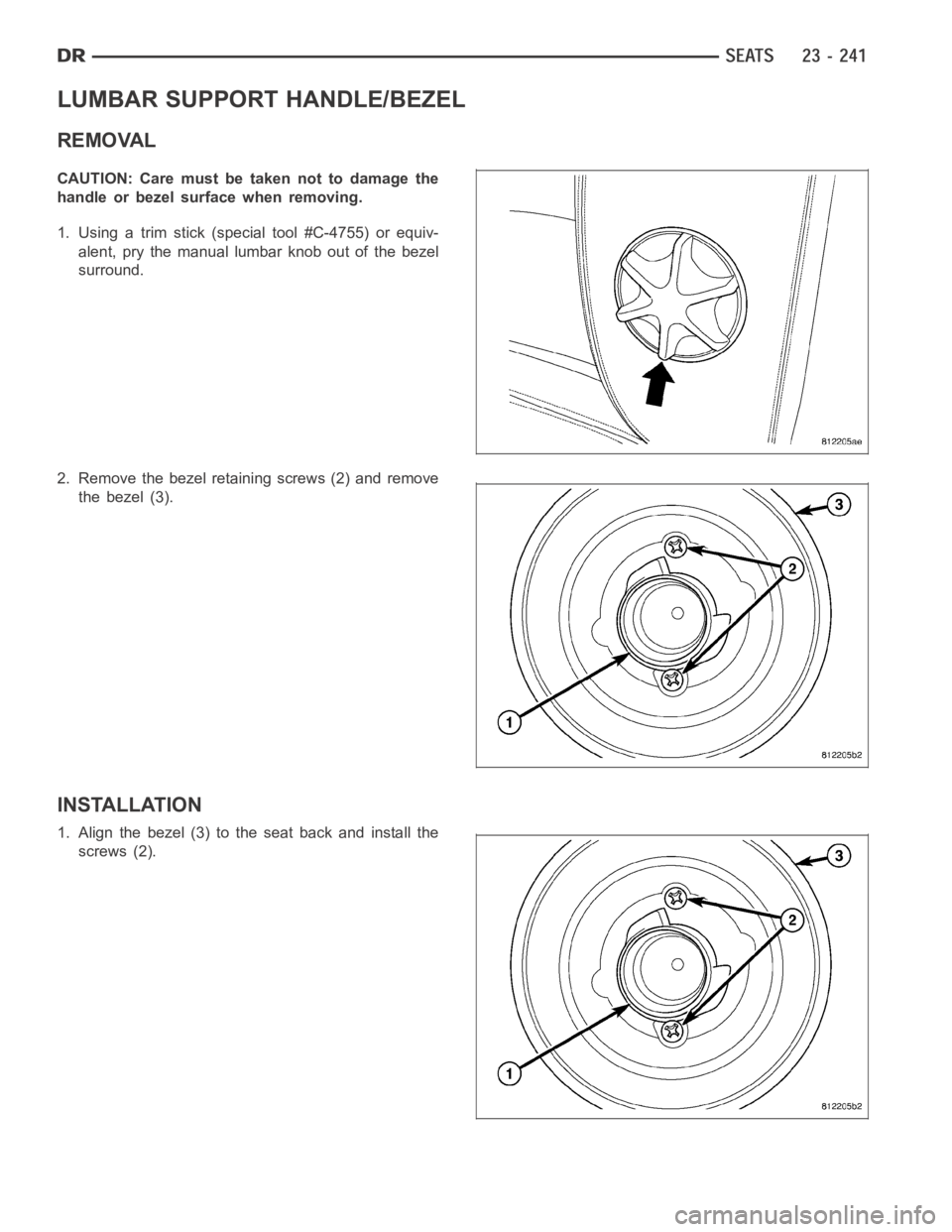
1. Using a trim stick (special tool #C-4755) or equiv-
alent, pry the manual lumbar knob out of the bezel
surround.
2. Remove the bezel retaining screws (2) and remove
the bezel (3).
INSTALLATION
1. Align the bezel (3) to the seat back and install the
screws (2).
Page 4579 of 5267
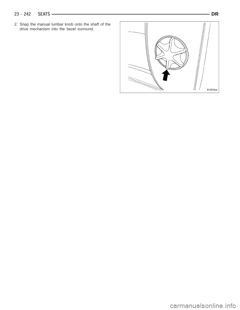
2. Snap the manual lumbar knob onto the shaft of the
drive mechanism into the bezel surround.
Page 4580 of 5267
SEAT CUSHION / COVER - FRONT
REMOVAL
1. Remove the front seat. (Refer to 23 -BODY/SEATS/SEAT - FRONT - REMOVAL)
2. Remove the screw and remove the recliner handle.
3. Remove the two screws and remove the power seat controls, if equipped, and disconnect the electrical connec-
tor.
4. Disconnect the j-straps and remove the seat cushion and cover.
INSTALLATION
1. Position the seat cushion and cover onto the frame assembly and connect the j-straps.
2. Connect the power seat control switch electrical connector, if equipped.
3. Install the power seat control switch and install the two screws, if equipped.
4. Install the recliner handle and install the screw.
5. Install the front seat. (Refer to 23 - BODY/SEATS/SEAT - FRONT - INSTALLATION)
Trending: weight, dead battery, radiator cap, door lock, immobilizer, battery capacity, oil type
