DODGE RAM SRT-10 2006 Service Repair Manual
RAM SRT-10 2006
DODGE
DODGE
https://www.carmanualsonline.info/img/12/56917/w960_56917-0.png
DODGE RAM SRT-10 2006 Service Repair Manual
Trending: gas tank size, spark plugs replace, manual transmission, alarm, CD changer, battery capacity, open hood
Page 4611 of 5267

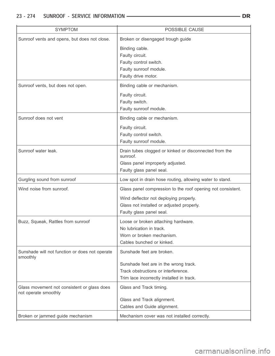
SYMPTOM POSSIBLE CAUSE
Sunroof vents and opens, but does not close. Broken or disengaged trough guide
Binding cable.
Faulty circuit.
Faulty control switch.
Faulty sunroof module.
Faulty drive motor.
Sunroof vents, but does not open. Binding cable or mechanism.
Faulty circuit.
Faulty switch.
Faulty sunroof module.
Sunroof does not vent Binding cable or mechanism.
Faulty circuit.
Faulty control switch.
Faulty sunroof module.
Sunroof water leak. Drain tubes clogged or kinked or disconnected from the
sunroof.
Glass panel improperly adjusted.
Faulty glass panel seal.
Gurgling sound from sunroof Low spot in drain hose routing, allowing waterto stand.
Wind noise from sunroof. Glass panel compression to the roof opening not consistent.
Wind deflector not deploying properly.
Glass not installed or adjusted properly.
Faulty glass panel seal.
Buzz, Squeak, Rattles from sunroof Loose or broken attaching hardware.
No lubrication in track.
Worn or broken mechanism.
Cables bunched or kinked.
Sunshade will not function or does not operate
smoothlySunshade feet are broken.
Sunshadefeetareinthewrongtrack.
Track obstructions or interference.
Trim lace incorrectly installed in track.
Glass movement not consistent or glass does
not operate smoothlyGlass and Track timing.
Glass and Track alignment.
Cables and Guide alignment.
Broken or jammed guide mechanism Mechanism cover was not installed correctly.
Page 4612 of 5267

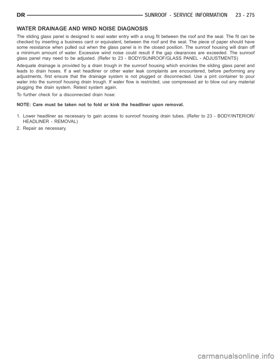
WATER DRAINAGE AND WIND NOISE DIAGNOSIS
The sliding glass panel is designed to seal water entry with a snug fit betweentheroofandtheseal.Thefitcanbe
checked by inserting a business card or equivalent, between the roof and the seal. The piece of paper should have
some resistance when pulled out when the glass panel is in the closed position. The sunroof housing will drain off
a minimum amount of water. Excessive wind noise could result if the gap clearances are exceeded. The sunroof
glass panel may need to be adjusted. (Refer to 23 - BODY/SUNROOF/GLASS PANEL - ADJUSTMENTS)
Adequate drainage is provided by a drain trough in the sunroof housing which encircles the sliding glass panel and
leads to drain hoses. If a wet headliner or other water leak complaints are encountered, before performing any
adjustments, first ensure that the drainage system is not plugged or disconnected. Use a pint container to pour
water into the sunroof housing drain trough. If water flow is restricted, use compressed air to blow out any material
plugging the drain system. Retest system again.
To further check for a disconnected drain hose:
NOTE: Care must be taken not to fold or kink the headliner upon removal.
1. Lower headliner as necessary to gain access to sunroof housing drain tubes. (Refer to 23 - BODY/INTERIOR/
HEADLINER - REMOVAL)
2. Repair as necessary.
Page 4613 of 5267
ASSEMBLY-MODULE
REMOVAL
WARNING: The Excessive Force Limitation (EFL)
feature must be calibrated any time a sunroof
motor/module is replaced with a new component.
Failure to perform this procedure could result in
vehicle damage and/or personal injury. (Refer to 8
- ELECTRICAL/POWER TOP/MOTOR - STANDARD
PROCEDURE - EXCESSIVE FORCE LIMITATION
(EFL) CALIBRATION) for the appropriate proce-
dure.
1. Move glass panel to the fully closed position.
2. Disconnect and isolate the battery negative cable.
3. Remove headliner (Refer to 23 - BODY/INTERIOR/
HEADLINER - REMOVAL).
4. Disconnect the sunroof wire harness electrical
connector.
5. Disconnect the four drain tubes (1) from sunroof
housing.
Page 4614 of 5267
6. With the aid of a helper, support the sunroof and remove the eight fasteners (2) attaching sunroof assembly (1)
to roof panel.
7. Remove the sunroof (1) from vehicle.
Page 4615 of 5267
INSTALLATION
WARNING: The Excessive Force Limitation (EFL) feature must be calibratedanytimeasunroofmotor/mod-
ule is replaced with a new component. Failure to perform this procedure could result in vehicle damage
and/or personal injury. (Refer to 8 - ELECTRICAL/POWER TOP/MOTOR - STANDARD PROCEDURE - EXCES-
SIVE FORCE LIMITATION (EFL) CALIBRATION) for the appropriate procedure.
1. Verify that glass panel is loose and slightly retracted.
2. Raise sunroof module assembly (1) and guide it carefully into position.
3. Hand start the eight screws (2).
4. Line up the locating holes and tighten the attaching screws (2) to 9 Nꞏm (80in.lbs.).
5. Connect the electrical connector (1).
Page 4616 of 5267
6. Connect the drain tubes (1) to the sunroof.
7. Adjust the sunroof glass. (Refer to 23 - BODY/
SUNROOF/GLASS PANEL - ADJUSTMENTS)
8. Connect battery negative cable.
9. Install the vehicle headliner, (Refer to 23 - BODY/
INTERIOR/HEADLINER - INSTALLATION).
10. Perform the sunroof position calibration, (Refer to
8 - ELECTRICAL/POWER TOP/MOTOR - STAN-
DARD PROCEDURE - SUNROOF POSITION
CALIBRATION).
11. Perform the Excessive Force Limitation (EFL) cal-
ibration, (Refer to 8 - ELECTRICAL/POWER TOP/
MOTOR - STANDARD PROCEDURE -
EXCESSIVE FORCE LIMITATION (EFL) CALI-
BRATION).
12. Verify proper operation of the power sunroof
system.
Page 4617 of 5267
CHANNEL-DRAIN
REMOVAL
1. Remove glass panel. (Refer to 23 - BODY/SUN-
ROOF/GLASS PANEL - REMOVAL)
2. Separate the drain channel arms (2) from the guide
mechanisms (1) one at a time.
CAUTION: Do not pry the channel arms apart at
thesametimeoryoucouldbreakthedrain
channel.
3. Carefully slide the drain channel (1) forward to the
notches (2) in the frame and remove from the
vehicle.
Page 4618 of 5267
INSTALLATION
1. Carefully position the drain channel (1) into the
notches (2) in the frame and slide rearward.
2. Install the drain channel arms (2) into the mecha-
nism (1) holes one at a time with the reinforce-
ments on the inside of mechanism arms.
CAUTION: Do not pry the channel arms apart at
the same time or you could break the drain chan-
nel.
3. Install the sunroof glass. (Refer to 23 - BODY/
SUNROOF/GLASS PANEL - INSTALLATION)
Page 4619 of 5267
COVER-GUIDE MECHANISM
REMOVAL
1. Move the glass panel to the full closed position.
2. Slide sunshade rearward to the open position.
3. Separate the mechanism covers (2) from the tabs
(1) on the glass panel.
4. Hold both mechanism covers down and open the
sunroof fully.
5. Slide the mechanism covers (1) out the front of the
guide in the frame (2).
Page 4620 of 5267
INSTALLATION
1. With the sunroof in the open position, snap the mechanism cover (2) into the lower guide channel.
2. Hold down each cover and close the sunroof.
3. Snap the upper portion of the cover (2) into the retaining clips (1) on theglass panel between the locating fea-
tures.
Trending: transmission, lock, sport mode, wiring, steering, battery location, bulb


