DODGE SPRINTER 2007 2.G Owners Manual
Manufacturer: DODGE, Model Year: 2007, Model line: SPRINTER, Model: DODGE SPRINTER 2007 2.GPages: 393, PDF Size: 7.61 MB
Page 201 of 393
200 OperationTires and wheels
4
Only use wheels and tires which have been
tested and approved by the vehicle manu-
facturer.
Warning
G
Do not use a tire, wheel size or rating other
than that specified for your Sprinter vehicle.
Some combinations of unapproved tires and
wheels may change suspension dimensions
and performance characteristics, resulting
in changes to steering, handling, and brak-
ing of your Sprinter vehicle. This can cause
unpredictable handling and stress to steer-
ing and suspension components. You could
lose control and have an accident resulting
in serious injury or death. Only use the tire
and wheel sizes with load ratings approved
for your Sprinter vehicle, refer to "Tire and
loading information".
Never use a tire with a smaller load index or
speed index or capacity other than what was
originally equipped on your Sprinter vehicle.
Using a tire with a smaller load index could
result in tire overloading and failure. You
could lose control and have an accident.
Failure to equip the vehicle with tires having
adequate speed capability can result in sud-
den tire failure and loss of vehicle control.
!
CAUTION
Replacing original tires with tires of a
different size may result in false speed-
ometer and odometer readings.
Warning
G
Worn, old tires can cause accidents. If the
tire tread is badly worn, or if the tires have
sustained damage, replace them.
When replacing rims, only use genuine
wheel bolts approved by the vehicle manu-
facturer and specified for the particular rim
type. Failure to do so can result in the bolts
loosening and possibly an accident.
Do not use retreaded/remolded tires. This
process does not always permit previous
damage to be detected. Therefore vehicle
safety cannot be guaranteed if retreaded/
remolded tires are fitted.
Warning
G
Fitting other wheel sizes to the vehicle will
change the vehicle’s handling characteris-
tics and may lead to an accident resulting in
death, severe personal injuries and property
damage.
Only certain tires meeting the tire size/
load/speed rating specifications are certi-
fied to conform to FMVSS 110 for the
Sprinter vehicle at this time. Please check
your side walls of your originally equipped
tires for specific makes/sizes, and speed
load ratings when you need to replace your
tires.
To prevent accidents resulting in possible
death, severe injury or property damage,
use only the tire and wheel sizes with load
ratings approved for your Sprinter vehicle
for your tire replacement.
Refer to "Tire and loading information"
(\2page 205).
Page 202 of 393
201 Operation
Tires and wheels
4
Cuts and punctures in radial tires are re-
pairable only in the tread area because of
side wall flexing. Consult an authorized tire
dealer for radial tire repairs.\4Only use sets of tires and rims of the
same type and make.
\4Tires must be of the correct size for the
rim.
\4Break in new tires for approximately
65 miles (100 km) at moderate
speeds.
\4Regularly check the tires and rims for
damage. Dented or bent rims can
cause tire inflation pressure loss or
damage to the tire beads.
\4If the vehicle is heavily loaded, check
tire inflation pressure and correct as
required.
\4Do not allow your tires to wear down
too far. Adhesion properties on wet
roads are sharply reduced at tread
depths under
1/8in (3 mm) for sum-
mer tires and
1/6in (4 mm) for winter
tires.
Radial-ply tiresWarning
G
Combining radial ply tires with other types
of tires on your Sprinter vehicle will change
the vehicle’s handling characteristics and
may lead to an accident resulting in death,
severe personal injuries and property dam-
age. Always use radial ply tires in sets of 4
(or 6, in case of vehicles with dual rear
wheels).
Never combine them with other types of
tires.
Tire valves (snap-in valves)Warning
G
Sprinter tire valves are tested and approved
under rough operating conditions.
The installation of additional hub caps or
other wheel simulators could cause damage
to the tire valve and lead to a loss of tire
pressure at the valve stem.
Do not install any of these parts on your
Sprinter vehicle. To help ensure safe and re-
liable operation of your Sprinter vehicle,
only use parts and accessories tested and
approved by the vehicle manufacturer for
your Sprinter vehicle.!
CAUTION
For safety reasons, the following tire
valves from the Schrader company
must be used on the vehicles:
\4TR 600 for vehicle model type 2500
\4TR 418 for vehicle model type 3500
Other tire valves could be damaged by
the specified tire pressures.Important guidelines
Page 203 of 393
202 OperationTires and wheels
4
\4When replacing individual tires, you
should mount new tires on the front
wheels first.
The tire inflation pressure should be
checked regularly, i.e. at least each time
you refuel the vehicle. The preferred inter-
val for checking the tire inflation pressure,
however, is before each trip.
For more information on checking tire in-
flation pressure, refer to "Recommended
tire inflation pressure" (\2page 210).Tire inspection
Every time when checking the tire inflation
pressure, the tires should also be inspect-
ed for the following:
\4excessive treadwear, refer to "Tread
depth". the condition of the tread
depths, i.e. uneven tread wear or ex-
cessive treadwear on one side. Turn
the front wheels to full lock if neces-
sary to enable you to check the inner
edge of the front tires more easily. You
must also always check the inside of
the tire tread on the rear wheels.
\4cord or fabric showing through the
tire’s rubber
\4bumps, bulges, cuts, cracks or splits in
the tread or side of the tire
\4foreign objects between the tires
(on vehicles with twin tires)
Replace the tire if any of the above condi-
tions is found.
Also inspect the spare tire periodically for
condition and inflation. Spare tires will age
and become worn over time even if never
used, and thus should be inspected and re-
placed when necessary.Tire damage
Tire damage can be caused
by:
\4the vehicle’s operating conditions
\4tire aging
\4curbs
\4foreign objects
\4insufficient or excessive tire pressures
\4weather and environmental influences
\4contact with oil, grease, fuel, etc.
Tire care and maintenanceWarning
G
Regularly check the tires for damage. Dam-
aged tires can cause tire inflation pressure
loss. As a result, you could lose control of
your vehicle.
Worn, old tires can cause accidents. If the
tire tread is badly worn, or if the tires have
sustained damage, replace them.
Warning
G
Driving over curbs or sharp-edged objects
can cause damage to the tire substructure
which is not visible from the outside.
Damage to the tire substructure cannot be
detected until later and can cause the tire to
burst.
\2\2
Page 204 of 393
203 Operation
Tires and wheels
4
Life of tire
The service life of a tire depends on varying
factors including but not limited to:
\4Driving style
\4Tire inflation pressure
\4Distance drivenTread depth
Do not allow your tires to wear down too
far. Adhesion properties on wet roads are
sharply reduced at tread depths under
1/8in (3 mm) for summer tires and
1/6in
(4 mm) for winter tires.
Treadwear indicators (TWI) are required by
law. These indicators are located in six
places on the tread circumference and be-
come visible at a tread depth of approxi-
mately
1/16
in (1.6 mm), at which point
the tire is considered worn and should be
replaced.
Recommended minimum tire tread depth:
\4Summer tires
1/8in (3 mm)
\4Winter tires
1/6in (4 mm)
You could lose control of the vehicle as a re-
sult, cause an accident and injure yourself
or others.
Avoid driving up against curbs or parking the
vehicle with part of the tire tread surface on
the curb.Warning
G
Tires and spare tire should be replaced after
6 years, regardless of the remaining tread.
Warning
G
Although the applicable federal motor safety
laws consider a tire to be worn when the
Treadwear Indicators (TWI) become visible
at approximately
1/16in (1.6 mm), we rec-
ommend that you do not allow your tires to
wear down to that level. As tread depth ap-
proaches
1/8in (3 mm) for summer tires or
1/6in (4 mm) for winter tires, the adhesion
properties on a wet road are sharply re-
duced.
Depending upon the weather and/or road
surface (conditions), the tire traction varies
widely.
Page 205 of 393
204 OperationTires and wheels
4
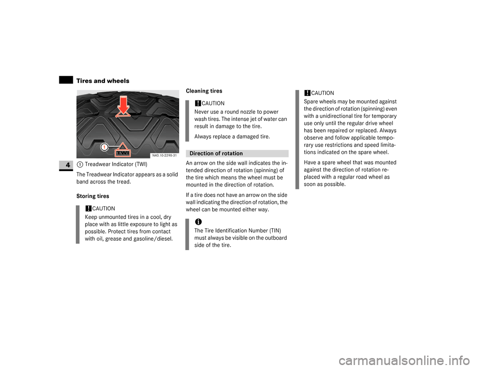
1Treadwear Indicator (TWI)
The Treadwear Indicator appears as a solid
band across the tread.
Storing tiresCleaning tires
An arrow on the side wall indicates the in-
tended direction of rotation (spinning) of
the tire which means the wheel must be
mounted in the direction of rotation.
If a tire does not have an arrow on the side
wall indicating the direction of rotation, the
wheel can be mounted either way.
!
CAUTION
Keep unmounted tires in a cool, dry
place with as little exposure to light as
possible. Protect tires from contact
with oil, grease and gasoline/diesel.
!
CAUTION
Never use a round nozzle to power
wash tires. The intense jet of water can
result in damage to the tire.
Always replace a damaged tire.
Direction of rotationiThe Tire Identification Number (TIN)
must always be visible on the outboard
side of the tire.
!
CAUTION
Spare wheels may be mounted against
the direction of rotation (spinning) even
with a unidirectional tire for temporary
use only until the regular drive wheel
has been repaired or replaced. Always
observe and follow applicable tempo-
rary use restrictions and speed limita-
tions indicated on the spare wheel.
Have a spare wheel that was mounted
against the direction of rotation re-
placed with a regular road wheel as
soon as possible.
Page 206 of 393
205 Operation
Tires and wheels
4
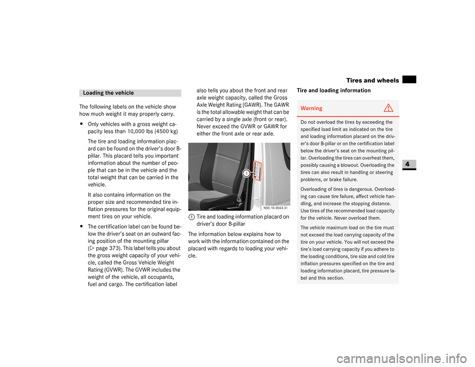
The following labels on the vehicle show
how much weight it may properly carry.
\4Only vehicles with a gross weight ca-
pacity less than 10,000 lbs (4500 kg)
The tire and loading information plac-
ard can be found on the driver’s door B-
pillar. This placard tells you important
information about the number of peo-
ple that can be in the vehicle and the
total weight that can be carried in the
vehicle.
It also contains information on the
proper size and recommended tire in-
flation pressures for the original equip-
ment tires on your vehicle.
\4The certification label can be found be-
low the driver’s seat on an outward fac-
ing position of the mounting pillar
(\2page 373). This label tells you about
the gross weight capacity of your vehi-
cle, called the Gross Vehicle Weight
Rating (GVWR). The GVWR includes the
weight of the vehicle, all occupants,
fuel and cargo. The certification label also tells you about the front and rear
axle weight capacity, called the Gross
Axle Weight Rating (GAWR). The GAWR
is the total allowable weight that can be
carried by a single axle (front or rear).
Never exceed the GVWR or GAWR for
either the front axle or rear axle.
1Tire and loading information placard on
driver’s door B-pillar
The information below explains how to
work with the information contained on the
placard with regards to loading your vehi-
cle.Tire and loading informationLoading the vehicle
Warning
G
Do not overload the tires by exceeding the
specified load limit as indicated on the tire
and loading information placard on the driv-
er’s door B-pillar or on the certification label
below the driver’s seat on the mounting pil-
lar. Overloading the tires can overheat them,
possibly causing a blowout. Overloading the
tires can also result in handling or steering
problems, or brake failure.
Overloading of tires is dangerous. Overload-
ing can cause tire failure, affect vehicle han-
dling, and increase the stopping distance.
Use tires of the recommended load capacity
for the vehicle. Never overload them.
The vehicle maximum load on the tire must
not exceed the load carrying capacity of the
tire on your vehicle. You will not exceed the
tire’s load carrying capacity if you adhere to
the loading conditions, tire size and cold tire
inflation pressures specified on the tire and
loading information placard, tire pressure la-
bel and this section.
Page 207 of 393
206 OperationTires and wheels
4
Placard
For vehicles with a gross weight capacity
less than 10,000 lbs (4500 kg) only.
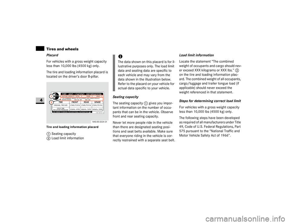
The tire and loading information placard is
located on the driver’s door B-pillar.Tire and loading information placard1Seating capacity
2Load limit informationSeating capacity
The seating capacity1 gives you impor-
tant information on the number of occu-
pants that can be in the vehicle. Observe
front and rear seating capacity.
Never let more people ride in the vehicle
than there are designated seating posi-
tions and seat belts available. Make sure
that everyone riding in the vehicle is cor-
rectly restrained with a separate seat belt.Load limit information
Locate the statement “The combined
weight of occupants and cargo should nev-
er exceed XXX kilograms or XXX lbs.” 2
on the tire and loading information plac-
ard. The combined weight of all occupants,
cargo/luggage and trailer tongue load (if
applicable) should never exceed the
weight referenced in that statement.
Steps for determining correct load limit
For vehicles with a gross weight capacity
less than 10,000 lbs (4500 kg) only.
The following steps have been developed
as required of all manufacturers under Title
49, Code of U.S. Federal Regulations, Part
575 pursuant to the “National Traffic and
Motor Vehicle Safety Act of 1966”.
iThe data shown on this placard is for il-
lustrative purposes only. The load limit
data and seating data are specific to
each vehicle and may vary from the
data shown in the illustration below.
Refer to the placard on your vehicle for
actual data specific to your vehicle.
Page 208 of 393
207 Operation
Tires and wheels
4
Step 1
\1Locate the statement “The combined
weight of occupants and cargo should
never exceed XXX kg or XXX lbs.” on
your vehicle’s placard.
Step 2
\1Determine the combined weight of the
driver and passengers that will be
riding in your vehicle.
Step 3
\1Subtract the combined weight of the
driver and passengers from
XXX kilograms or XXX lbs.Step 4
\1The resulting figure equals the avail-
able amount of cargo and luggage load
capacity. For example, if the “XXX”
amount equals 1400 lbs and there will
be five 150 lbs passengers in your vehi-
cle, the amount of available cargo and
luggage load capacity is 650 lbs (1400-
750 (5 x150) = 650 lbs).
Step 5
\1Determine the combined weight of lug-
gage and cargo being loaded on the ve-
hicle. That weight may not safely
exceed the available cargo and luggage
load capacity calculated in step 4.Step 6 (if applicable)
\1If your vehicle will be towing a trailer,
load from your trailer will be trans-
ferred to your vehicle. Consult this
manual to determine how this reduces
the available cargo and luggage load
capacity of your vehicle.
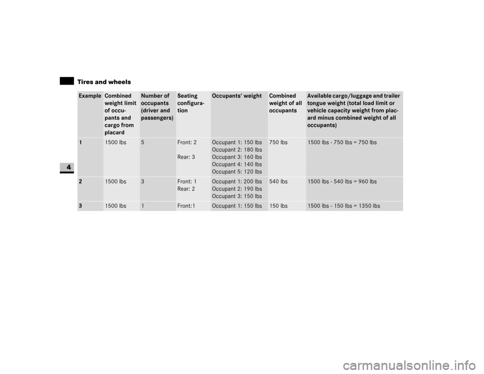
The following table shows examples on
how to calculate total load, cargo load and
towing capacities with varying seating con-
figurations and number and size of occu-
pants. The following examples use a load
limit of 1500 lbs. This is for illustrative
purposes only. Make sure you are using
the actual load limit for your vehicle stated
on the vehicle’s tire and loading informa-
tion placard (\2page 206).
The higher the weight of all occupants, the
less cargo and luggage load capacity is
available.
Page 209 of 393
208 OperationTires and wheels
4
Example
Combined
weight limit
of occu-
pants and
cargo from
placard
Number of
occupants
(driver and
passengers)
Seating
configura-
tion
Occupants' weight
Combined
weight of all
occupants
Available cargo/luggage and trailer
tongue weight (total load limit or
vehicle capacity weight from plac-
ard minus combined weight of all
occupants)
1
1500 lbs
5
Front: 2
Rear: 3
Occupant 1: 150 lbs
Occupant 2: 180 lbs
Occupant 3: 160 lbs
Occupant 4: 140 lbs
Occupant 5: 120 lbs
750 lbs
1500 lbs - 750 lbs = 750 lbs
2
1500 lbs
3
Front: 1
Rear: 2
Occupant 1: 200 lbs
Occupant 2: 190 lbs
Occupant 3: 150 lbs
540 lbs
1500 lbs - 540 lbs = 960 lbs
3
1500 lbs
1
Front:1
Occupant 1: 150 lbs
150 lbs
1500 lbs - 150 lbs = 1350 lbs
Page 210 of 393
209 Operation
Tires and wheels
4
Certification label
Even after careful determination of the
combined weight of all occupants, cargo
and the trailer tongue load (if applicable)
as to not exceed the permissible load limit,
you must make sure that your vehicle nev-
er exceeds the Gross Vehicle Weight Rat-
ing (GVWR) and the Gross Axle Weight
Rating (GAWR) for either the front or rear
axle and the Gross Combination Weights
Rating (GCWR) (if applicable).
Under a maximum loaded vehicle condi-
tion, gross axle weight ratings (GAWR’s) for
the front and rear axles must not be ex-
ceeded. USA only - for vehicles with a gross weight
capacity less than 10,000 lbs (4500 kg)
only:
To determine the maximum loading condi-
tions of your vehicle, locate the statement
"The combined weight of occupants and
cargo should never exceed XXX kg or
XXX lbs." on the tire and loading informa-
tion placard. The combined weight of occu-
pants, cargo/luggage and trailer tongue
weight (if applicable) should never exceed
the weight referenced here.
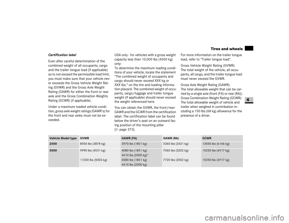
You can obtain the GVWR, the front/rear-
GAWR and the GCWR from the certification
label. The certification label can be found
below the driver’s seat on an outward fac-
ing position of the mounting pillar
(\2page 373).For more information on the trailer tongue
load, refer to "Trailer tongue load".
Gross Vehicle Weight Rating (GVWR):
The total weight of the vehicle, all occu-
pants, all cargo, and the trailer tongue load
must never exceed the GVWR.
Gross Axle Weight Rating (GAWR):
The total allowable weight that can be car-
ried by a single axle (front (FA) or rear (RA)).
Gross Combination Weight Rating (GCWR):
The total allowable weight of vehicle and
trailer when weighed in cominbation in-
cluding a 150 lbs (68 kg) allowance for the
presence of a driver.
Vehicle Model type
GVWR
GAWR (FA)
GAWR (RA)
GCWR
2500
8550 lbs (3878 kg)
3970 lbs (1801 kg)
5360 lbs (2431 kg)
13550 lbs (6146 kg)
3500
9990 lbs (4531 kg)
11030 lbs (5003 kg)
4080 lbs (1851 kg)
4410 lbs (2000 kg)*
4080 lbs (1851 kg)
4410 lbs (2000 kg)
7060 lbs (3202 kg)
7720 lbs (3502 kg)
15250 lbs (6917 kg)
15250 lbs (6917 kg)