DODGE TRUCK 1993 Service Repair Manual
Manufacturer: DODGE, Model Year: 1993, Model line: TRUCK, Model: DODGE TRUCK 1993Pages: 1502, PDF Size: 80.97 MB
Page 101 of 1502
2
- 48
FRONT
SUSPENSION
AND
AXLE
•
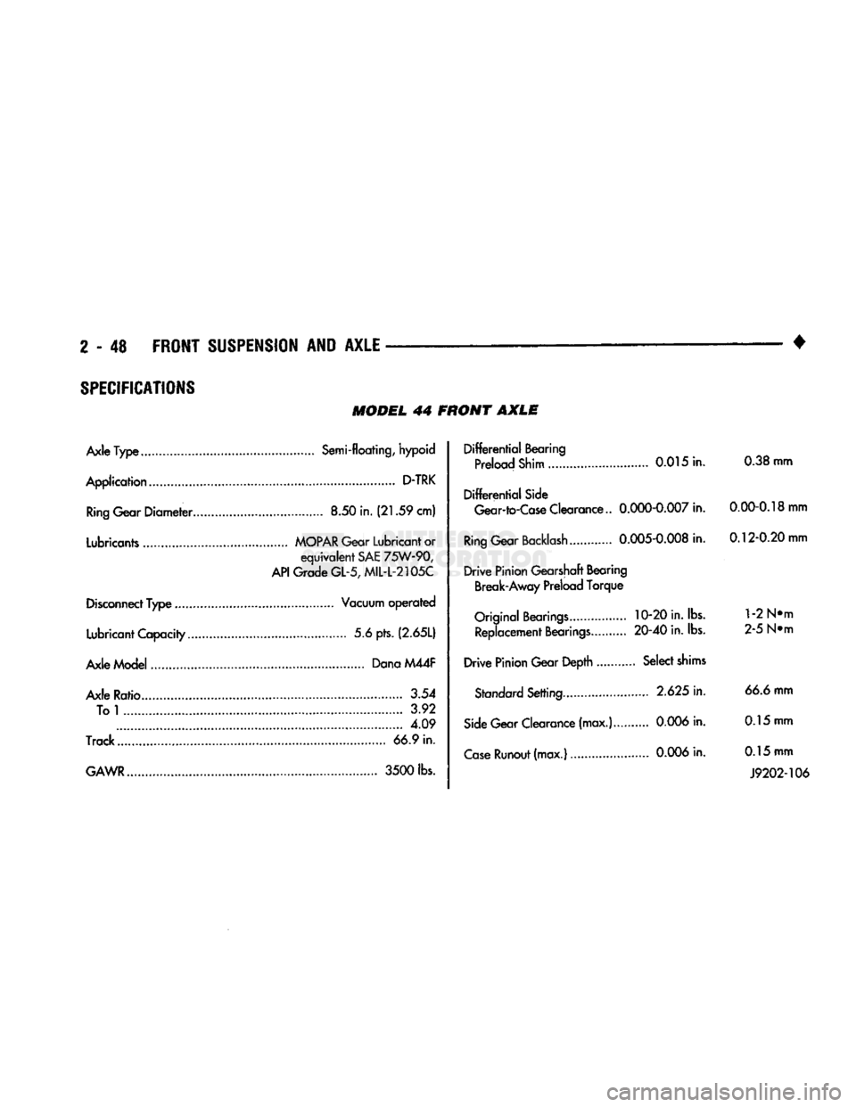
SPECIFICATIONS
MODEL
44 FRONT
AXLE
Axle
Type
Semi-floating, hypoid
Application
D-TRK
Ring
Gear
Diameter
8.50 in.
(21.59
cm)
Lubricants
MOPAR
Gear Lubricant or
equivalent
SAE
75W-90,
API
Grade
GL-5,
MIL-L-2105C
Disconnect
Type
Vacuum
operated
Lubricant Capacity 5.6 pts.
(2.65L)
Axle Model Dana M44F
Axle Ratio.. 3.54 To
1
3.92 4.09
Track
66.9 in.
GAWR
3500
lbs.
Differential
Bearing
Preload Shim 0.015 in. 0.38 mm
Differential
Side
Gear-to-Case
Clearance..
0.000-0.007
in.
0.00-0.18
mm
Ring
Gear
Backlash
0.005-0.008
in.
0.12-0.20
mm
Drive
Pinion Gearshaft Bearing Break-Away Preload
Torque
Original
Bearings
10-20 in. lbs.
1
-2 N»m Replacement
Bearings
20-40
in. lbs. 2-5 N»m
Drive
Pinion Gear Depth Select
shims
Standard
Setting
2.625
in. 66.6 mm
Side
Gear Clearance (max.)...
0.006
in. 0.15 mm
Case
Runout
(max.)
0.006
in. 0.15 mm
J9202-106
Page 102 of 1502
•
FRONT
SUSPENSION
AND
AXLE
2 - 49
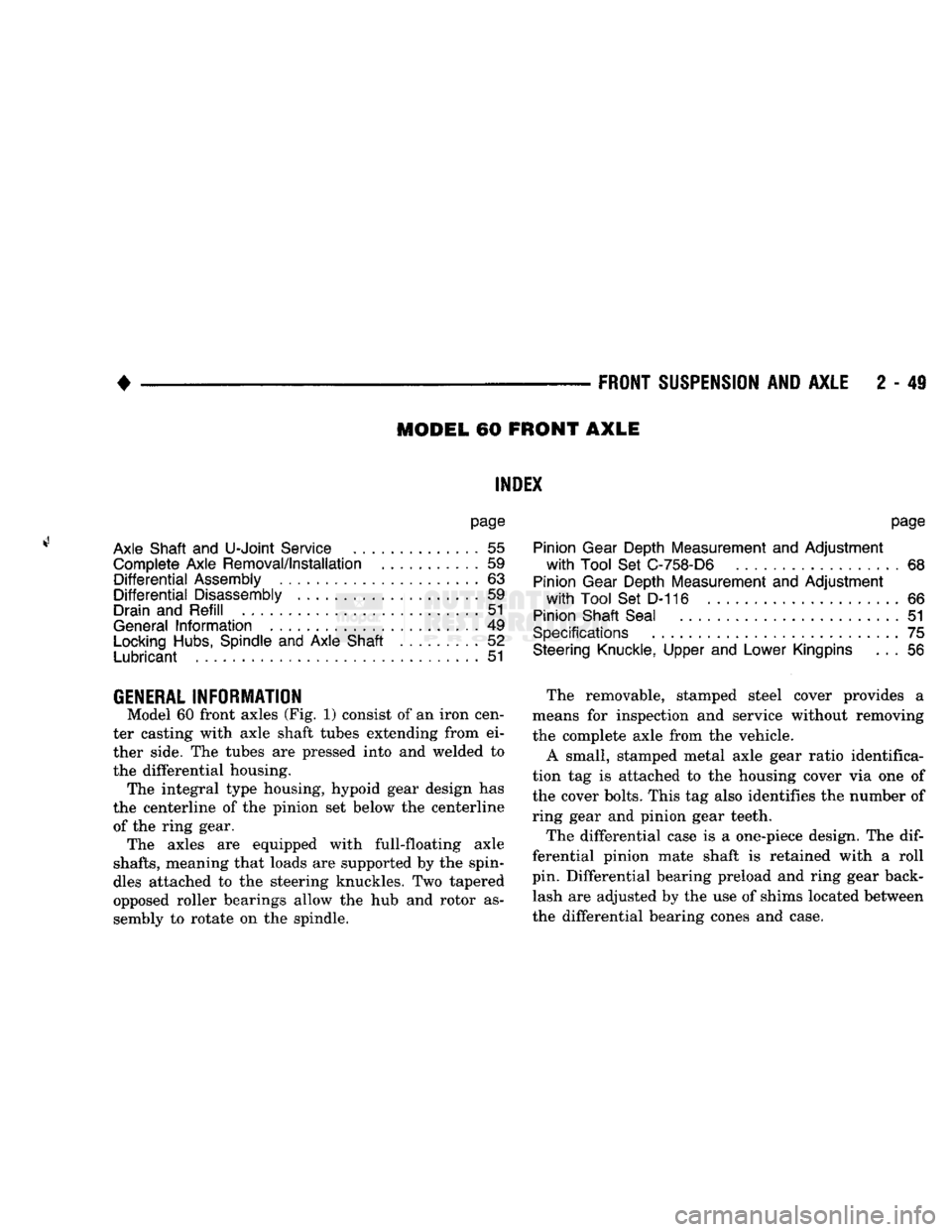
MODEL
60 FRONT
AXLE
INDEX
page
Axle Shaft
and
U-Joint
Service
55
Complete Axle Removal/Installation
59
Differential
Assembly
63
Differential
Disassembly
59
Drain
and Refill
51
General
Information
49
Locking
Hubs,
Spindle
and
Axle Shaft
52
Lubricant
51
page
Pinion Gear Depth Measurement
and
Adjustment
with
Tool
Set
C-758-D6
68
Pinion Gear Depth Measurement
and
Adjustment
with
Tool
Set
D-116
66
Pinion Shaft Seal
51
Specifications
75
Steering Knuckle, Upper
and
Lower Kingpins
. . . 56
GENERAL
INFORMATION
Model
60
front axles
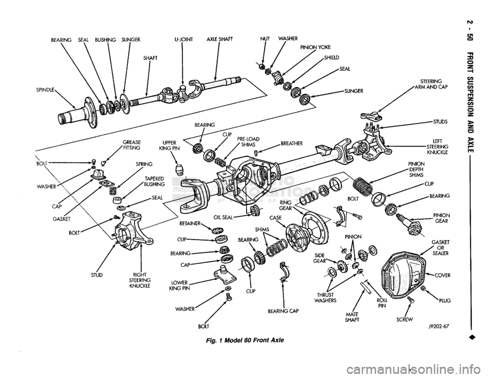
(Fig. 1)
consist
of an
iron cen
ter casting with axle shaft tubes extending from
ei
ther side.
The
tubes
are
pressed into
and
welded
to
the differential housing. The integral type housing, hypoid gear design
has
the centerline
of the
pinion
set
below
the
centerline of
the
ring gear. The axles
are
equipped with full-floating axle
shafts,
meaning that loads
are
supported
by the
spin
dles attached
to the
steering knuckles.
Two
tapered
opposed roller bearings allow
the hub and
rotor
as
sembly
to
rotate
on the
spindle. The removable, stamped steel cover provides
a
means
for
inspection
and
service without removing
the complete axle from
the
vehicle.
A small, stamped metal axle gear ratio identifica
tion
tag is
attached
to the
housing cover
via one of
the cover bolts. This
tag
also identifies
the
number
of
ring gear
and
pinion gear teeth.
The differential case
is a
one-piece design.
The dif
ferential pinion mate shaft
is
retained with
a
roll
pin. Differential bearing preload
and
ring gear back lash
are
adjusted
by the use of
shims located between
the differential bearing cones
and
case.
Page 103 of 1502
BEARING SEAL BUSHING SLINGER
U-JOINT
AXLE
SHAFT
NUT
WASHER
SPINDLE STEERING
ARM AND CAP
STUDS
LEFT
STEERING KNUCKLE
BEARING CAP
f
BOLT
Fig. 1 Model 60 Front Axle
MATE
SHAFT
SCREW
GASKET
OR
SEALER
COVER
PLUG
J9202-67
oi
30
O
e
m
22
o
>•
x
w
Page 104 of 1502
FRONT
SUSPENSION
AND
AXLE
2 - 51
LUBRICANT
Multi-purpose API GL 5 quality hypoid gear lubri
cant should be used for Model 60 axles. MOPAR Hy
poid Gear Lubricant conforms to these specifications and is recommended.
CAUTION:
If a front axle is
submerged
in
water,
the
axle lubricant
must
be replaced immediately.
DRAIN AND REFILL
(1) Drive the vehicle until the gear lubricant
reaches normal operating temperature. (2) Raise and support the vehicle.
(3) Remove the lubricant fill hole plug from the
differential housing cover. (4) Remove the differential housing cover. Allow
the original lubricant to completely drain from the
housing and axle shaft tubes. (5) With standard differential, clean the differen
tial and the housing cavity with a flushing oil (or light engine oil). This will remove the residual lubricant and foreign matter. Do not use water, steam,
kerosene or gasoline for flushing. (6) Scrape the residual gasket from the housing
and cover mating surfaces. Clean the mating sur
faces with mineral spirits. Install a new cover gas
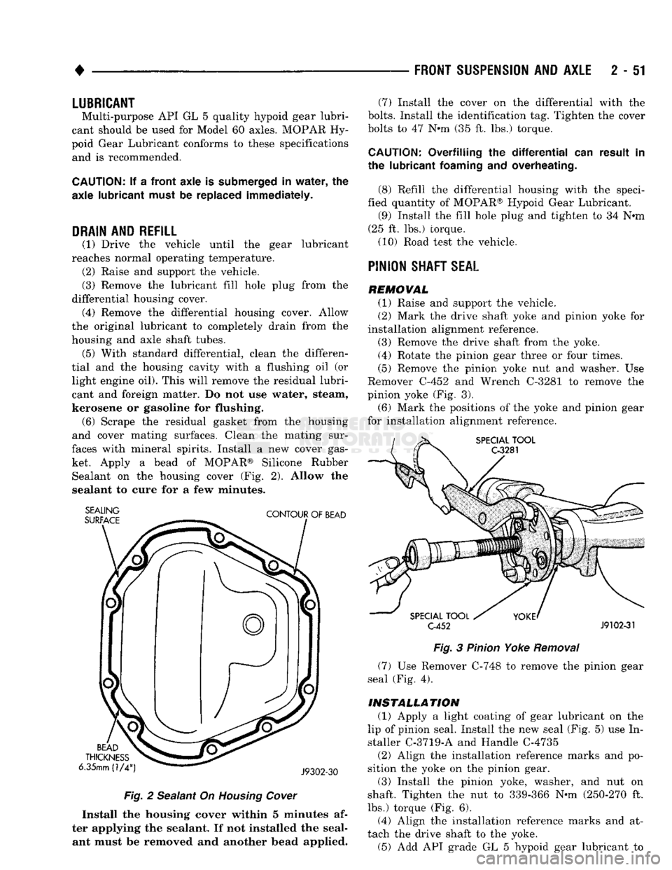
ket. Apply a bead of MOPAR® Silicone Rubber Sealant on the housing cover (Fig. 2). Allow the
sealant to cure for a few minutes.
SEALING
SURFACE
CONTOUR
OF
BEAD
BEAD
THICKNESS
6.35mm (1/4
J9302-30
Fig.
2 Sealant On
Housing
Cover
Install the housing cover within 5 minutes af
ter applying the sealant. If not installed the seal ant must be removed and another bead applied. (7) Install the cover on the differential with the
bolts.
Install the identification tag. Tighten the cover
bolts to 47 Nnn (35 ft. lbs.) torque.
CAUTION:
Overfilling the
differential
can result in
the lubricant
foaming
and overheating.
(8) Refill the differential housing with the speci
fied quantity of MOPAR® Hypoid Gear Lubricant. (9) Install the fill hole plug and tighten to 34 N«m
(25 ft. lbs.) torque. (10) Road test the vehicle.
PINION
SHAFT
SEAL
REMOVAL (1) Raise and support the vehicle.
(2) Mark the drive shaft yoke and pinion yoke for
installation alignment reference.
(3) Remove the drive shaft from the yoke.
(4) Rotate the pinion gear three or four times.
(5) Remove the pinion yoke nut and washer. Use
Remover C-452 and Wrench C-3281 to remove the
pinion yoke (Fig. 3).
(6) Mark the positions of the yoke and pinion gear
for installation alignment reference.
SPECIAL
TOOL
C-3281
SPECIAL
TOOL
C-452
J9102-31
Fig.
3
Pinion
Yoke
Removal
(7) Use Remover C-748 to remove the pinion gear
seal (Fig. 4).
INSTALLATION
(1) Apply a light coating of gear lubricant on the
lip of pinion seal. Install the new seal (Fig. 5) use In
staller C-3719-A and Handle C-4735
(2) Align the installation reference marks and po
sition the yoke on the pinion gear.
(3) Install the pinion yoke, washer, and nut on
shaft. Tighten the nut to 339-366 N-m (250-270 ft.
lbs.) torque (Fig. 6).
(4) Align the installation reference marks and at
tach the drive shaft to the yoke. (5) Add API grade GL 5 hypoid gear lubricant to
Page 105 of 1502
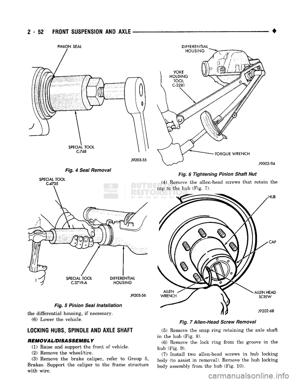
2
- 52
FRONT
SUSPENSION
AND
AXLE
•
PINION
SEAL
J9203-55
Fig. 4 Seal Removal
SPECIAL TOOL
G4735
J9203-56
Fig. 5 Pinion Seal Installation the differential housing, if necessary.
(6)
Lower the vehicle.
LOCKING HUBS, SPINDLE AND AXLE SHAFT
REM0VAL/D1SASSEMBL
Y
(1) Raise and support the front of vehicle. (2) Remove the wheel/tire.
(3) Remove the brake caliper, refer to Group 5,
Brakes. Support the caliper to the frame structure
with wire. DIFFERENTIAL
Fig. 6 Tightening Pinion Shaft Nut
(4) Remove the allen-head screws that retain the
cap to the hub (Fig. 7).
Fig. 7 Allen-Head Screw Removal (5) Remove the snap ring retaining the axle shaft
in the hub (Fig. 8).
(6)
Remove the lock ring from the groove in the
hub (Fig. 9).
(7) Install two allen-head screws in hub locking
body (to assist in removal). Remove the hub locking
body assembly from the hub (Fig. 10).
Page 106 of 1502
• ___— . ^
FRONT
SUSPENSION
AND
AXLE
2 - 53
SCREWDRIVER
J9202-70
Fig.
9
Lock
Ring
Removal
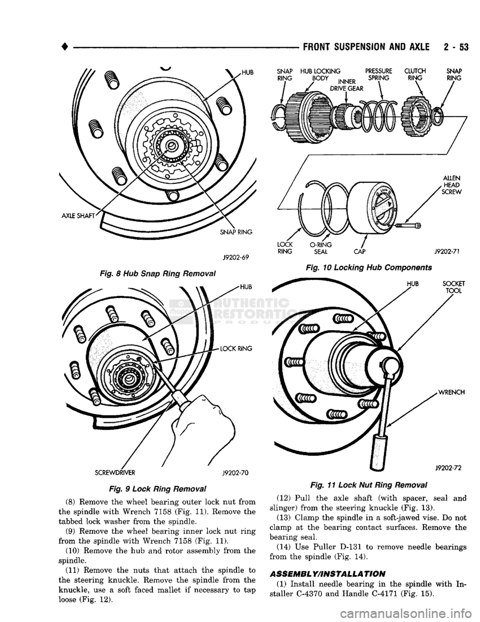
(8) Remove the wheel bearing outer lock nut from
the spindle with Wrench 7158 (Fig. 11). Remove the
tabbed lock washer from the spindle.
(9) Remove the wheel bearing inner lock nut ring
from the spindle with Wrench 7158 (Fig. 11).
(10) Remove the hub and rotor assembly from the
spindle.
(11) Remove the nuts that attach the spindle to
the steering knuckle. Remove the spindle from the knuckle, use a soft faced mallet if necessary to tap
loose (Fig. 12).
SNAP
HUB
LOCKING
PRESSURE
CLUTCH
SNAP
RING
SEAL
CAP
J9202-71
Fig.
10
Locking
Hub
Components
Fig.
11
Lock
Nut
Ring
Removal
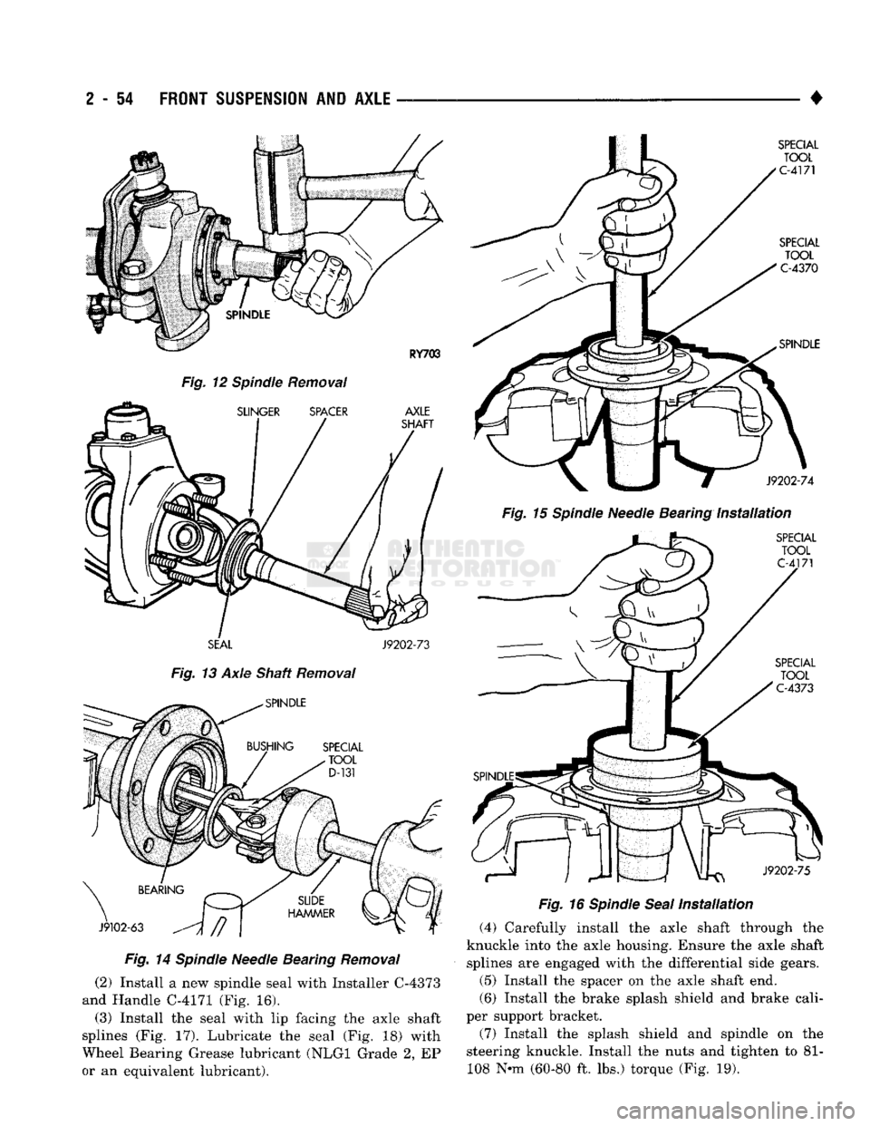
(12) Pull the axle shaft (with spacer, seal and
slinger) from the steering knuckle (Fig. 13).
(13) Clamp the spindle in a soft-jawed vise. Do not
clamp at the bearing contact surfaces. Remove the
bearing seal.
(14) Use Puller D-131 to remove needle bearings
from the spindle (Fig. 14).
ASSEMBL
Y/INSTALLA
TION
(1) Install needle bearing in the spindle with In
staller C-4370 and Handle C-4171 (Fig. 15).
Page 107 of 1502
2
- 54
FRONT SUSPENSION
AND
AXLE
Fig.
12 Spindle Removal
SEAL
J9202-73
Fig.
13 Axle Shaft Removal
Fig.
14
Spindle
Needle Bearing
Removal
(2) Install a new spindle seal with Installer C-4373
and Handle C-4171 (Fig. 16).
(3) Install the seal with lip facing the axle shaft
splines (Fig. 17). Lubricate the seal (Fig. 18) with
Wheel Bearing Grease lubricant (NLGI Grade 2, EP
or an equivalent lubricant). •
Fig.
15
Spindle
Needle Bearing
Installation
Fig.
16
Spindle
Seal
Installation
(4) Carefully install the axle shaft through the
knuckle into the axle housing. Ensure the axle shaft splines are engaged with the differential side gears.
(5) Install the spacer on the axle shaft end.
(6) Install the brake splash shield and brake cali
per support bracket.
(7) Install the splash shield and spindle on the
steering knuckle. Install the nuts and tighten to 81- 108 N-m (60-80 ft. lbs.) torque (Fig. 19).
Page 108 of 1502
•
Fig.
17 Axle Shaft
Seal
Installation
Fig.
19
Spindle
Installation
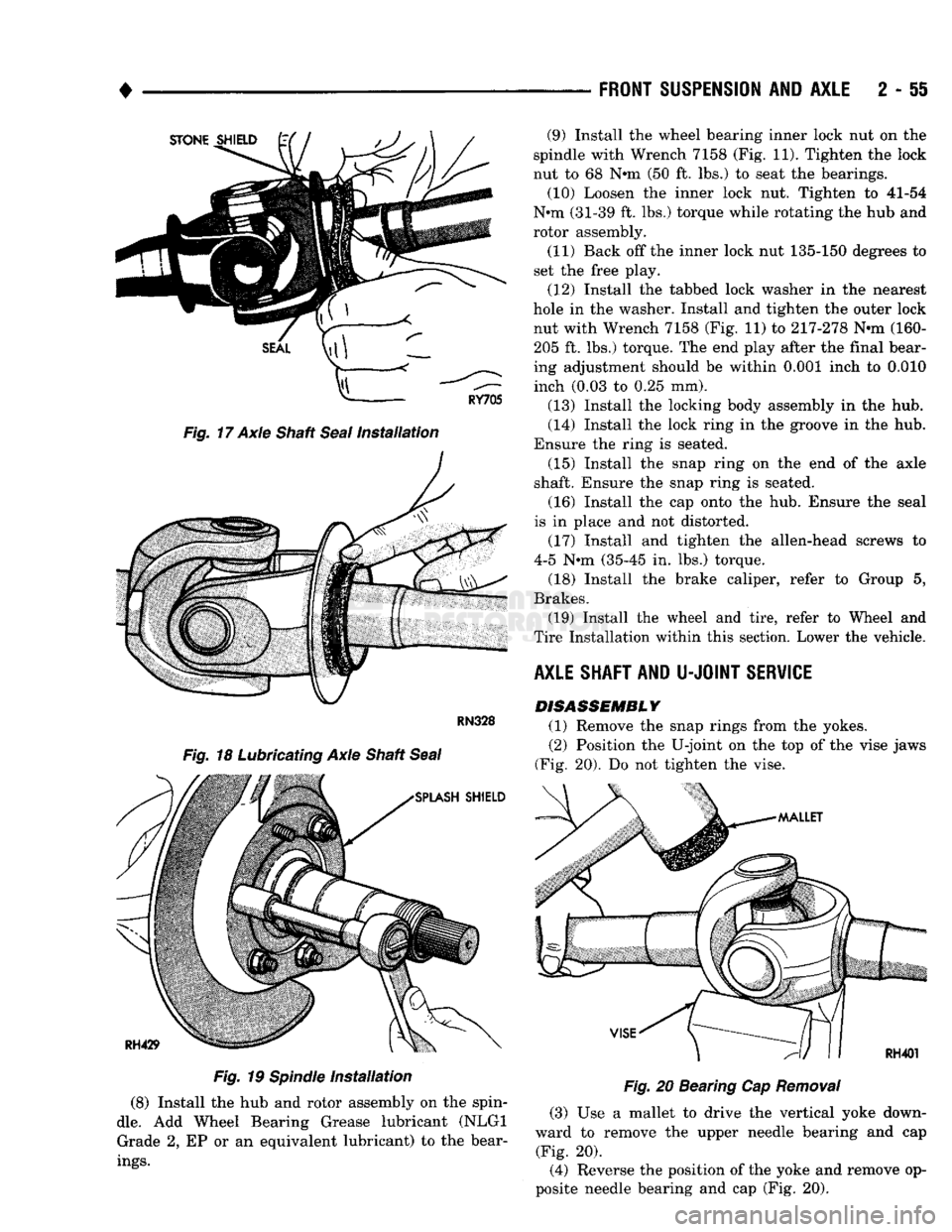
(8) Install the hub and rotor assembly on the spin
dle.
Add Wheel Bearing Grease lubricant (NLGI Grade 2, EP or an equivalent lubricant) to the bear
ings.
FRONT
SUSPENSION
AND
AXLE
2 - 51
Fig.
20 Bearing Cap
Removal
(3) Use a mallet to drive the vertical yoke down
ward to remove the upper needle bearing and cap (Fig. 20).
(4) Reverse the position of the yoke and remove op
posite needle bearing and cap (Fig. 20). (9) Install the wheel bearing inner lock nut on the
spindle with Wrench 7158 (Fig. 11). Tighten the lock
nut to 68 N*m (50 ft. lbs.) to seat the bearings. (10) Loosen the inner lock nut. Tighten to 41-54
N*m (31-39 ft. lbs.) torque while rotating the hub and
rotor assembly.
(11) Back off the inner lock nut 135-150 degrees to
set the free play.
(12) Install the tabbed lock washer in the nearest
hole in the washer. Install and tighten the outer lock nut with Wrench 7158 (Fig. 11) to 217-278 N-m (160-205 ft. lbs.) torque. The end play after the final bear
ing adjustment should be within 0.001 inch to 0.010 inch (0.03 to 0.25 mm).
(13) Install the locking body assembly in the hub.
(14) Install the lock ring in the groove in the hub.
Ensure the ring is seated. (15) Install the snap ring on the end of the axle
shaft. Ensure the snap ring is seated.
(16) Install the cap onto the hub. Ensure the seal
is in place and not distorted.
(17) Install and tighten the allen-head screws to
4-5 N-m (35-45 in. lbs.) torque.
(18) Install the brake caliper, refer to Group 5,
Brakes. (19) Install the wheel and tire, refer to Wheel and
Tire Installation within this section. Lower the vehicle.
AXLE SHAFT AND
U-JOINT
SERVICE DISASSEMBLY
(1) Remove the snap rings from the yokes.
(2) Position the U-joint on the top of the vise jaws
(Fig. 20). Do not tighten the vise.
Page 109 of 1502
2
- 56
FRONT
SUSPENSION
AND
AXLE
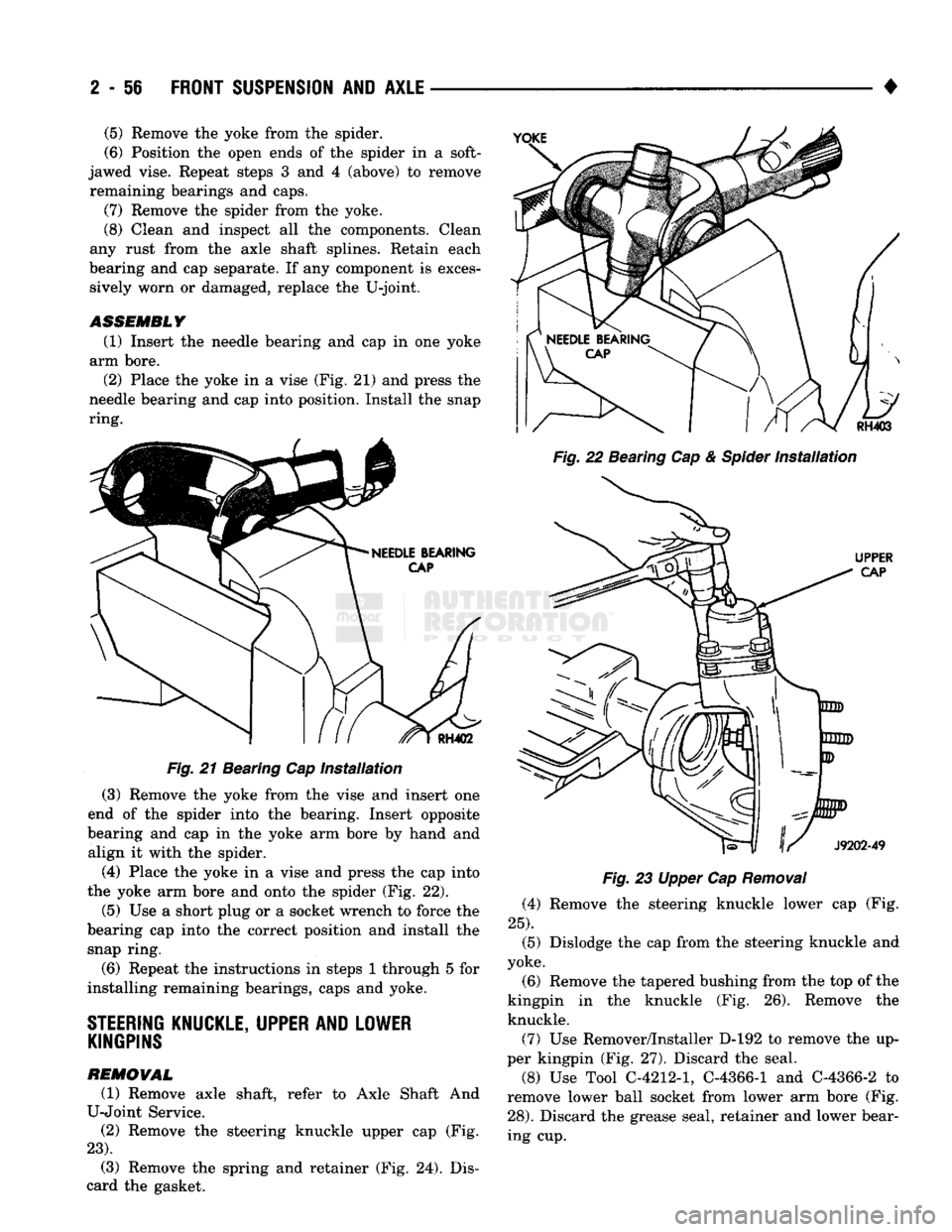
Fig. 21 Bearing Cap installation (3) Remove the yoke from the vise and insert one
end of the spider into the bearing. Insert opposite
bearing and cap in the yoke arm bore by hand and align it with the spider.
(4) Place the yoke in a vise and press the cap into
the yoke arm bore and onto the spider (Fig. 22).
(5)
Use a short plug or a socket wrench to force the
bearing cap into the correct position and install the snap ring.
(6) Repeat the instructions in steps 1 through 5 for
installing remaining bearings, caps and yoke.
STEERING
KNUCKLE, UPPER AND LOWER KINGPINS
REMOVAL
(1) Remove axle shaft, refer to Axle Shaft And
U-Joint Service. (2) Remove the steering knuckle upper cap (Fig.
23).
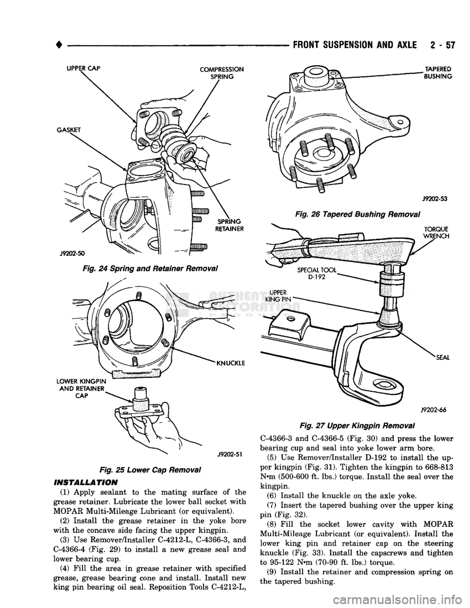
(3) Remove the spring and retainer (Fig. 24). Dis
card the gasket. •
Fig. 22 Bearing Cap & Spider Installation
Fig. 23 Upper Cap Removal (4) Remove the steering knuckle lower cap (Fig.
25).
(5) Dislodge the cap from the steering knuckle and
yoke.
(6) Remove the tapered bushing from the top of the
kingpin in the knuckle (Fig. 26). Remove the knuckle.
(7) Use Remover/Installer D-192 to remove the up
per kingpin (Fig, 27). Discard the seal.
(8) Use Tool C-4212-1, C-4366-1 and C-4366-2 to
remove lower ball socket from lower arm bore (Fig.
28).
Discard the grease seal, retainer and lower bear
ing cup.
(5)
Remove the yoke from the spider.
(6) Position the open ends of the spider in a soft-
jawed vise. Repeat steps 3 and 4 (above) to remove remaining bearings and caps.
(7) Remove the spider from the yoke.
(8) Clean and inspect all the components. Clean
any rust from the axle shaft splines. Retain each
bearing and cap separate. If any component is exces sively worn or damaged, replace the U-joint.
ASSEMBLY
(1) Insert the needle bearing and cap in one yoke
arm bore.
(2) Place the yoke in a vise (Fig. 21) and press the
needle bearing and cap into position. Install the snap
ring.
Page 110 of 1502
•
FRONT
SUSPENSION
AND
AXLE
2 - 57
Fig.
24
Spring
and Retainer
Removal
LOWER KINGPIN
AND
RETAINER
CAP
^
J9202-51
Fig.
25
Lower
Cap
Removal
INSTALLATION (1) Apply sealant to the mating surface of the
grease retainer. Lubricate the lower ball socket with
MOPAR Multi-Mileage Lubricant (or equivalent).
(2) Install the grease retainer in the yoke bore
with the concave side facing the upper kingpin.
(3) Use Remover/Installer C-4212-L, C-4366-3, and
C-4366-4 (Fig. 29) to install a new grease seal and
lower bearing cup.
(4) Fill the area in grease retainer with specified
grease, grease bearing cone and install. Install new
king pin bearing oil seal. Reposition Tools C-4212-L,
TAPERED
BUSHING
J9202-53
Fig.
26 Tapered
Bushing
Removal
J9202-66
Fig.
27 Upper
Kingpin
Removal
C-4366-3 and C-4366-5 (Fig. 30) and press the lower
bearing cup and seal into yoke lower arm bore.
(5) Use Remover/Installer D-192 to install the up
per kingpin (Fig. 31). Tighten the kingpin to 668-813 N-m (500-600 ft. lbs.) torque. Install the seal over the
kingpin.
(6) Install the knuckle on the axle yoke.
(7) Insert the tapered bushing over the upper king
pin (Fig. 32).
(8) Fill the socket lower cavity with MOPAR
Multi-Mileage Lubricant (or equivalent). Install the
lower king pin and retainer cap on the steering
knuckle (Fig. 33). Install the capscrews and tighten
to 95-122 N-m (70-90 ft. lbs.) torque.
(9) Install the retainer and compression spring on
the tapered bushing.