DODGE TRUCK 1993 Service Owners Manual
Manufacturer: DODGE, Model Year: 1993, Model line: TRUCK, Model: DODGE TRUCK 1993Pages: 1502, PDF Size: 80.97 MB
Page 91 of 1502
2
- 38
FRONT
SUSPENSION
AND
AXLE
•
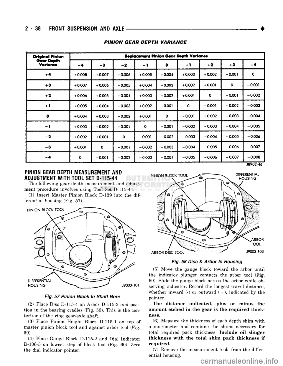
PINION GEAR DEPTH VARIANCE
Or§@ift^i
Linton
IsptocMnwtt
HnS®n
Oior Itoplli
fflttanct
Or§@ift^i
Linton
-4
-2
-1
0
+
1
-ft
+3
+4
+4
+
0.008
+
0.007
+
0.006
+
0.005
+
0.004
+
0.003
+
0.002
+
0.001
0
+3
+
0.007
+
0.006
+
0.005
+
0.004
+
0.003
+
0.002
+
0.001
0
-0.001
+2
+
0.006
+
0.005
+
0.004
+
0.003
+
0.002
+
0.001
0
-0.001
-0.002
+
1
+
0.005
+
0.004
+
0.003
+
0.002
+
0.001
0
-0.001
-0.002
-0.003
0
+
0.004
+
0.003
+
0.002
+
0.001
0
-0.001
-0.002
-0.003
-0.004
-1
+
0.003
+
0.002
+
0.001
0
-0.001
-0.002
-0.003 -0.004
-0.005
-2
+
0.002
+
0.001
. 0
-0.001
-0.002
-0.003 -0.004
-0.005 -0.006
-3
+
0.001
0
-0.001
-0.002
-0.003 -0.004
-0.005 -0.006
-0.007
-.4
0
-0.001
-0.002
-0.003 -0.004 -0.005
-0.006
-0.007
-0.008
PINION
GEAR
DEPTH
MEASUREMENT
AND
ADJUSTMENT
WITH TOOL SET D-11144
The following gear depth measurement and adjust
ment procedure involves using Tool Set D-115-44. (1) Insert Master Pinion Block D-139 into the
dif
ferential housing (Fig. 57).
PINION BLOCK TOOL PINION BLOCK TOOL
J8902-46
DIFFERENTIAL
HOUSING
ARBOR
DISC
TOOL
ARBOR
TOOL
J9003-103
DIFFERENTIAL
HOUSING
J9003-101
Fig.
57
Pinion
Block
In Shaft
Bore
(2) Place Disc D-115-4 on Arbor D-115-3 and posi
tion in the bearing cradles (Fig. 58). This is the cen
terline of the ring gear/axle shaft. (3) Place Pinion Height Block D-115-1 on top of
master pinion block tool and against arbor tool (Fig.
59).
(4) Place Gauge Block D-115-2 and Dial Indicator
D-106-5 on lowest step of block tool (Fig. 60). Zero
the dial indicator pointer.
Fig.
58
Disc
&
Arbor
In
Housing
(5) Move the gauge block toward the arbor until
the indicator plunger contacts the arbor tool (Fig.
60).
Slide the gauge block across the arbor while ob
serving indicator. Record the longest travel distance,
whether inward (-) or outward (+•), indicated by the
pointer.
The distance indicated, plus or minus the
amount etched in the gear is the required thick
ness.
(6) Measure the thickness of each depth shim with
a micrometer and combine the shims necessary for
total required pack thickness. Include oil slinger
thickness with the total shim pack thickness if
required.
(7) Remove the measurement tools from the differ
ential housing.
Page 92 of 1502
•
FRONT
SUSPENSION
AND
AXLE
2 - 39
Fig.
59
Pinion
Height
Block
Against
Arbor
Fig.
60
Pinion
Gear Depth Measurement
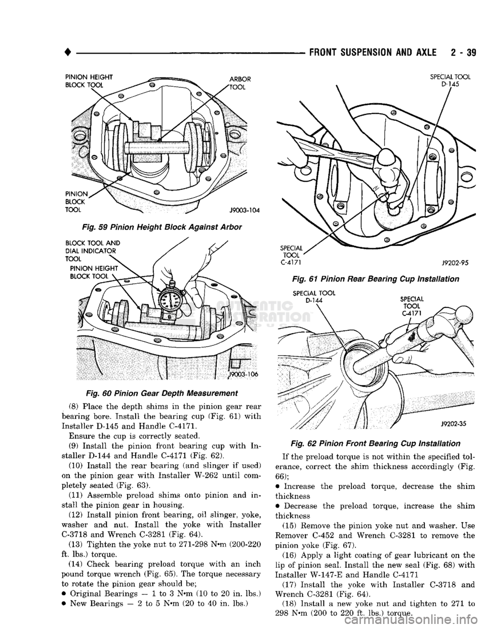
(8) Place the depth shims in the pinion gear rear
bearing bore. Install the bearing cup (Fig. 61) with Installer D-145 and Handle C-4171.
Ensure the cup is correctly seated. (9) Install the pinion front bearing cup with In
staller D-144 and Handle C-4171 (Fig. 62).
(10) Install the rear bearing (and slinger if used)
on the pinion gear with Installer W-262 until com
pletely seated (Fig. 63).
(11) Assemble preload shims onto pinion and in
stall the pinion gear in housing.
(12) Install pinion front bearing, oil slinger, yoke,
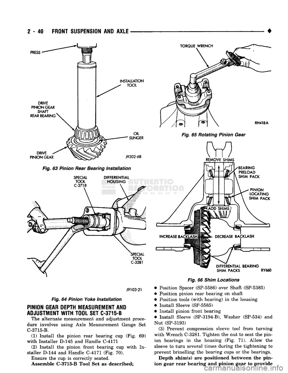
washer and nut. Install the yoke with Installer C-3718 and Wrench C-3281 (Fig. 64).
(13) Tighten the yoke nut to 271-298 N-m (200-220
ft. lbs.) torque. (14) Check bearing preload torque with an inch
pound torque wrench (Fig. 65). The torque necessary
to rotate the pinion gear should be;
• Original Bearings — 1 to 3 N*m (10 to 20 in. lbs.)
• New Bearings — 2 to 5 N*m (20 to 40 in. lbs.)
SPECIAL
TOOL
C-4171
J9202-95
Fig.
61
Pinion
Rear Bearing Cup
Installation
SPECIAL
TOOL
D-144
SPECIAL Fig.
62
Pinion
Front Bearing Cup
Installation
If the preload torque is not within the specified tol
erance, correct the shim thickness accordingly (Fig.
66);
• Increase the preload torque, decrease the shim
thickness
• Decrease the preload torque, increase the shim
thickness
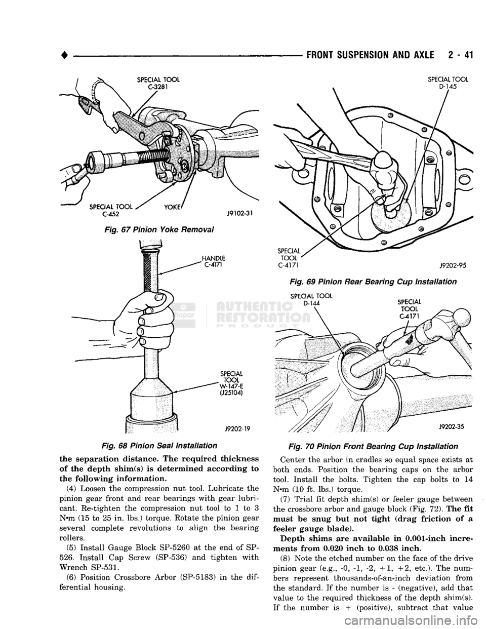
(15) Remove the pinion yoke nut and washer. Use
Remover C-452 and Wrench C-3281 to remove the
pinion yoke (Fig. 67).
(16) Apply a light coating of gear lubricant on the
lip of pinion seal. Install the new seal (Fig. 68) with
Installer W-147-E and Handle C-4171
(17) Install the yoke with Installer C-3718 and
Wrench C-3281 (Fig. 64). (18) Install a new yoke nut and tighten to 271 to
298 N-m (200 to 220 ft. lbs.) torque.
Page 93 of 1502
2
- 40
FRONT
SUSPENSION
AND
AXLE
•
SHIM PACKS
RY660
J9103-21
Fig.
64
Pinion
Yoke
Installation
PINION
GEAR
DEPTH
MEASUREMENT AND
ADJUSTMENT
WITH
TOOL
SET
C-3715-B The alternate measurement and adjustment proce
dure involves using Axle Measurement Gauge Set C-3715-B. (1) Install the pinion rear bearing cup (Fig. 69)
with Installer D-145 and Handle C-4171 (2) Install the pinion front bearing cup with In
staller D-144 and Handle C-4171 (Fig. 70). Ensure the cup is correctly seated.
Assemble
C-3715-B
Tool Set as described;
Fig.
66
Shim
Locations
• Position Spacer (SP-5586) over Shaft (SP-5385)
• Position pinion rear bearing on shaft
• Position tools (with bearing) in the housing
• Install Sleeve (SP-5585)
• Install pinion front bearing
m Install Sleeve (SP-3194-B), Washer (SP-534) and Nut (SP-3193) (3) Prevent compression sleeve tool from turning
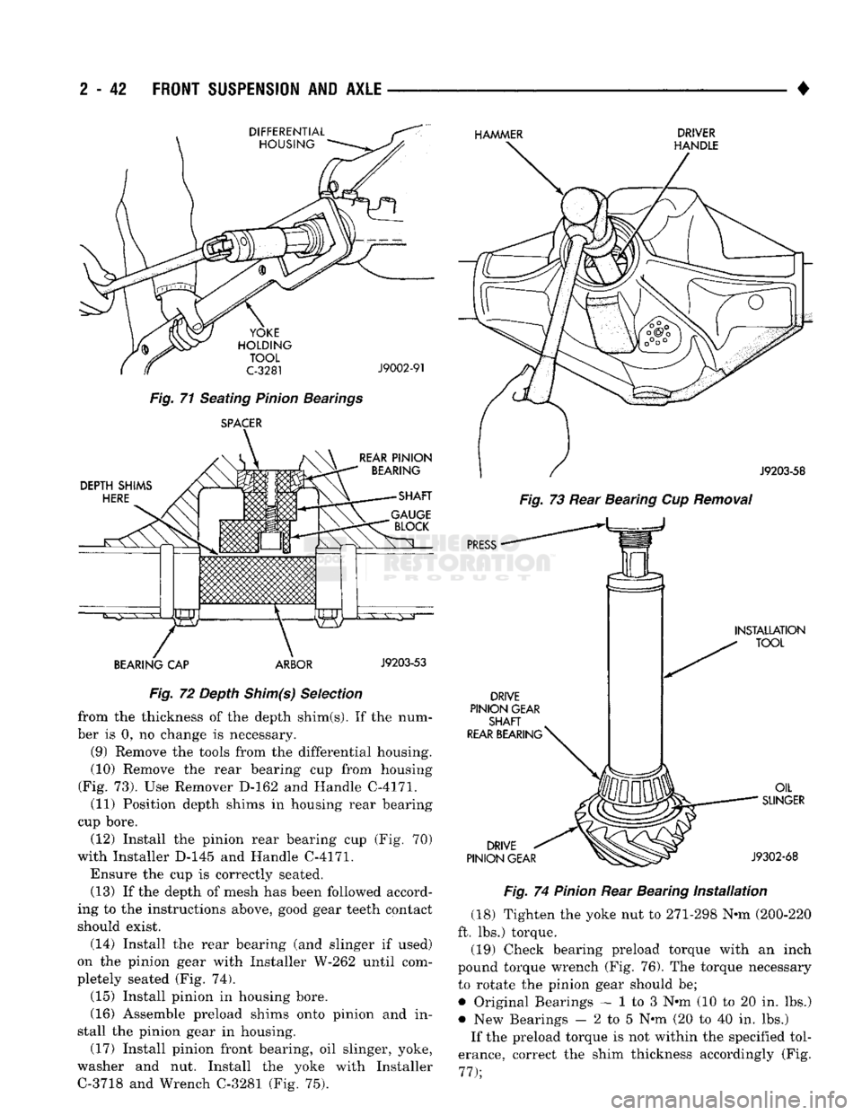
with Wrench C-3281. Tighten the nut to seat the pin
ion bearings in the housing (Fig. 71). Allow the
sleeve to turn several times during the tightening to
prevent brinelling the bearing cups or the bearings.
Depth shim(s) are positioned between the pin
ion gear rear bearing and pinion gear to provide
Page 94 of 1502
•
FRONT
SUSPENSION
AND
AXLE
2 - 41
SPECIAL
TOOL
D-145
Fig.
67
Pinion
Yoke
Removal
HANDLE
C-4171
SPECIAL
TOOL
C-4171
J9202-95 Fig.
69
Pinion
Rear Bearing Cup
Installation
SPECIAL
TOOL
D-144
SPECIAL
TOOL
C-4171
SPECIAL
TOOL
W-147-E
(J25104)
J9202-19
Fig.
68
Pinion
Seal
Installation
the separation distance. The required thickness
of the depth shim(s) is determined according to
the following information.
(4) Loosen the compression nut tool. Lubricate the
pinion gear front and rear bearings with gear lubri cant. Re-tighten the compression nut tool to 1 to 3
N«m (15 to 25 in. lbs.) torque. Rotate the pinion gear
several complete revolutions to align the bearing
rollers.
(5) Install Gauge Block SP-5260 at the end of SP-
526.
Install Cap Screw (SP-536) and tighten with
Wrench
SP-531.
(6) Position Crossbore Arbor (SP-5183) in the
dif
ferential housing.
J9202-35
Fig.
70
Pinion
Front Bearing Cup
Installation
Center the arbor in cradles so equal space exists at
both ends. Position the bearing caps on the arbor
tool. Install the bolts. Tighten the cap bolts to 14 N*m (10 ft. lbs.) torque.
(7) Trial fit depth shim(s) or feeler gauge between
the crossbore arbor and gauge block (Fig. 72). The fit must be snug but not tight (drag friction of a
feeler gauge blade).
Depth shims are available in 0.001-inch incre
ments from 0.020 inch to 0.038 inch.
(8) Note the etched number on the face of the drive
pinion gear (e.g., -0, -1, -2, +1, +2, etc.). The num
bers represent thousands-of-an-inch deviation from
the standard. If the number is - (negative), add that value to the required thickness of the depth shim(s).
If the number is + (positive), subtract that value
Page 95 of 1502
2
- 42
FRONT
SUSPENSION
AND
AXLE
DIFFERENTIAL HOUSING HAMMER
DRIVER
HANDLE
YOKE
HOLDING TOOL
C-3281
Fig.
71 Seating Pinion Bearings SPACER
J9002-91
DEPTH
SHIMS
HERE
REAR
PINION
BEARING
SHAFT
BEARING
CAP ARBOR
J9203-53
Fig.
72 Depth Shim(s) Selection from the thickness of the depth shim(s). If the num
ber is 0, no change is necessary.
(9) Remove the tools from the differential housing.
(10) Remove the rear bearing cup from housing
(Fig. 73). Use Remover D-162 and Handle C-4171. (11) Position depth shims in housing rear bearing
cup bore.
(12) Install the pinion rear bearing cup (Fig. 70)
with Installer D-145 and Handle C-4171.
Ensure the cup is correctly seated. (13) If the depth of mesh has been followed accord
ing to the instructions above, good gear teeth contact
should exist.
(14) Install the rear bearing (and slinger if used)
on the pinion gear with Installer W-262 until com
pletely seated (Fig. 74).
(15) Install pinion in housing bore.
(16) Assemble preload shims onto pinion and in
stall the pinion gear in housing. (17) Install pinion front bearing, oil slinger, yoke,
washer and nut. Install the yoke with Installer C-3718 and Wrench C-3281 (Fig. 75).
J9203-58
Fig.
73 Rear Bearing Cup
Removal
PRESS
•
DRIVE
PINION
GEAR
SHAFT
REAR BEARING
^
INSTALLATION
TOOL
DRIVE
PINION
GEAR
OIL
SUNGER
J9302-68
Fig.
74
Pinion
Rear Bearing
Installation
(18) Tighten the yoke nut to 271-298 N-m (200-220
ft. lbs.) torque.
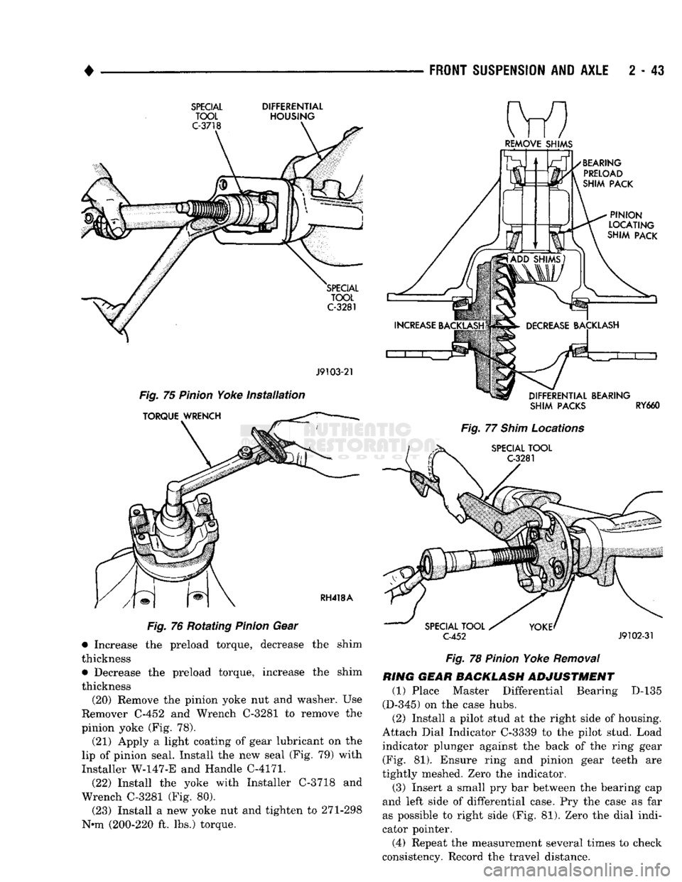
(19) Check bearing preload torque with an inch
pound torque wrench (Fig. 76). The torque necessary to rotate the pinion gear should be;
• Original Bearings — 1 to 3 N-m (10 to 20 in. lbs.)
• New Bearings — 2 to 5 N-m (20 to 40 in. lbs.) If the preload torque is not within the specified tol
erance, correct the shim thickness accordingly (Fig.
77);
Page 96 of 1502
FRONT SUSPENSION
AND
AXLE
2 43
SPECIAL
DIFFERENTIAL
TOOL
HOUSING J9103-21
Fig. 75 Pinion Yoke Installation
Fig. 76 Rotating Pinion Gear • Increase the preload torque, decrease the shim
thickness • Decrease the preload torque, increase the shim
thickness
(20) Remove the pinion yoke nut and washer. Use
Remover C-452 and Wrench C-3281 to remove the
pinion yoke (Fig. 78).
(21) Apply a light coating of gear lubricant on the
lip of pinion seal. Install the new seal (Fig. 79) with
Installer
W-147-E
and Handle C-4171.
(22) Install the yoke with Installer C-3718 and
Wrench C-3281 (Fig. 80).
(23) Install a new yoke nut and tighten to 271-298
N*m (200-220 ft. lbs.) torque.
REMOVE
SHIMS
SHIM
PACKS
RY660
Fig. 77 Shim Locations
C-452
J9102-31
Fig. 78 Pinion Yoke Removal
RING
GEAR BACKLASH
ADJUSTMENT
(1) Place Master Differential Bearing D-135
(D-345) on the case hubs.
(2) Install a pilot stud at the right side of housing.
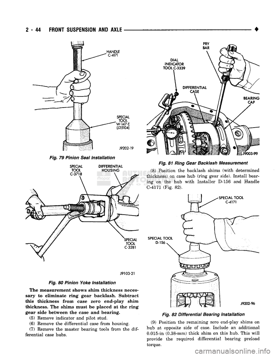
Attach Dial Indicator C-3339 to the pilot stud. Load indicator plunger against the back of the ring gear (Fig. 81). Ensure ring and pinion gear teeth are
tightly meshed. Zero the indicator.
(3) Insert a small pry bar between the bearing cap
and left side of differential case. Pry the case as far
as possible to right side (Fig. 81). Zero the dial indi
cator pointer.
(4) Repeat the measurement several times to check
consistency. Record the travel distance.
Page 97 of 1502
2
- 44
FRONT
SUSPENSION
AND
AXLE
Fig.
79
Pinion
Seal
Installation
SPECIAL
DIFFERENTIAL
TOOL
HOUSING
J9103-21
Fig.
80
Pinion
Yoke Installation The measurement shows shim thickness neces
sary to eliminate ring gear backlash. Subtract
this thickness from case zero end-play shim
thickness. The shims must be placed at the ring gear side between the case and bearing.
(5) Remove indicator and pilot stud.
(6) Remove the differential case from housing.
(7) Remove the master bearing tools from the
dif
ferential case hubs. •
Fig.
81
Ring
Gear
Backlash
Measurement (8) Position the backlash shims (with determined
thickness) on case hub (ring gear side). Install bear ing on the hub with Installer D-156 and Handle
C-4171 (Fig. 82).
Fig.
82
Differential
Bearing Installation
(9) Position the remaining zero end-play shims on
hub at opposite side of case. Include an additional 0.015-in (0.38-mm) thick shim on this hub. This will
provide the required differential bearing preload torque.
Page 98 of 1502
4
____________
(10) Install bearing
on hub
with Installer
D-156
and Handle C-4171
(Fig. 82).
(11) Install
new
axle shaft
oil
seal
in
differential
housing with Installer D-112-44. Apply lubricant
to
lip
of
seal. (12) Match each bearing
cup
with bearing (origi
nal).
Install
the
cups
on the
bearings.
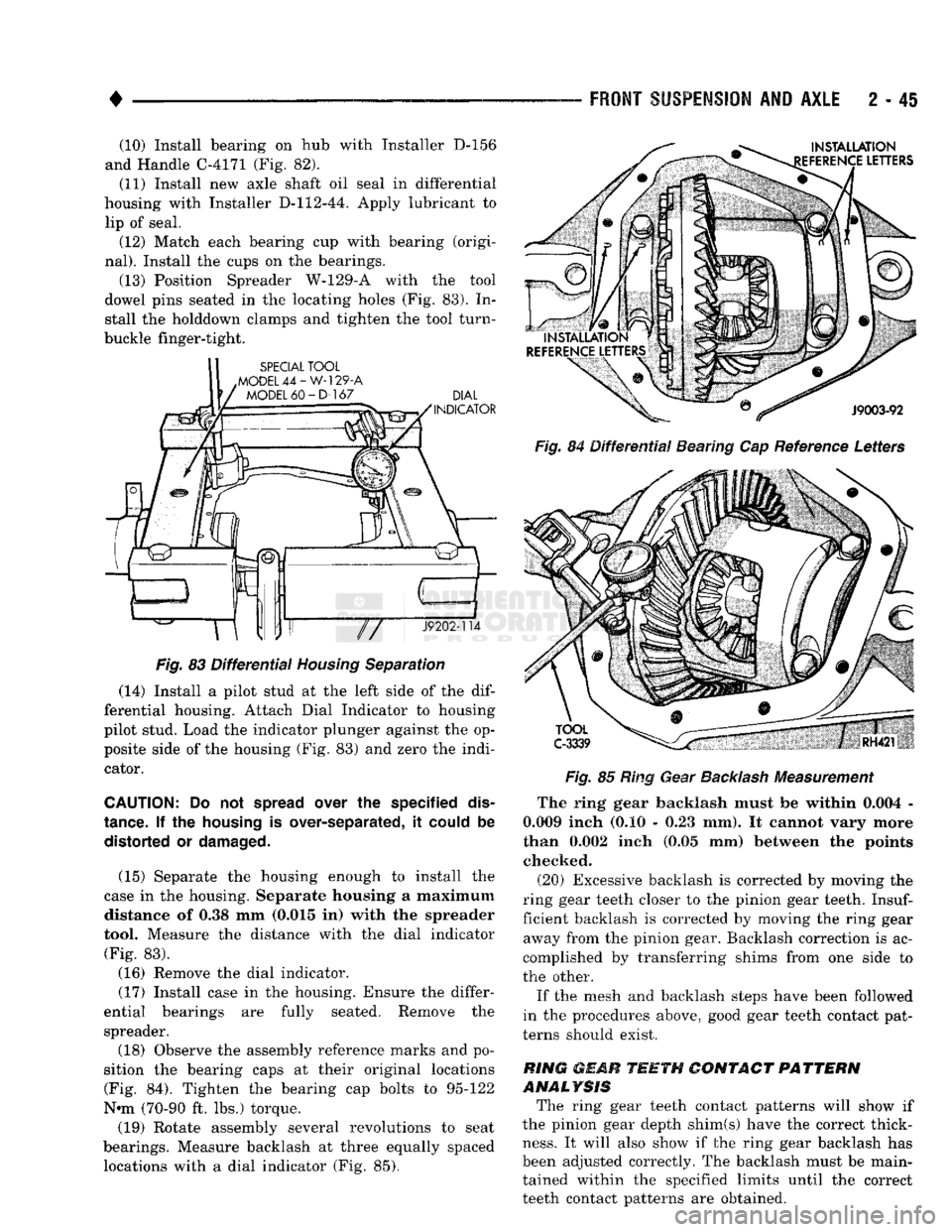
(13) Position Spreader W-129-A with
the
tool
dowel pins seated
in the
locating holes
(Fig. 83). In
stall
the
holddown clamps
and
tighten
the
tool turn-
buckle finger-tight.
Fig.
83
Differential
Housing
Separation
(14) Install
a
pilot stud
at the
left side
of the dif
ferential housing. Attach Dial Indicator
to
housing
pilot stud. Load
the
indicator plunger against
the op
posite side
of the
housing
(Fig. 83) and
zero
the
indi cator.
CAUTION:
Do not
spread
over
the
specified
dis
tance.
If the
housing
is
over-separated,
it
could
be
distorted
or
damaged.
(15) Separate
the
housing enough
to
install
the
case
in the
housing. Separate housing
a
maximum distance
of 0.38 mm
(0.015
in)
with
the
spreader
tool. Measure
the
distance with
the
dial indicator (Fig.
83).
(16) Remove
the
dial indicator.
(17) Install case
in the
housing. Ensure
the
differ
ential bearings
are
fully seated. Remove
the
spreader.
(18) Observe
the
assembly reference marks
and po
sition
the
bearing caps
at
their original locations (Fig.
84).
Tighten
the
bearing
cap
bolts
to
95-122
N-m (70-90
ft. lbs.)
torque.
(19) Rotate assembly several revolutions
to
seat
bearings. Measure backlash
at
three equally spaced locations with
a
dial indicator
(Fig. 85).
FRONT
SUSPENSION
AND
AXLE
2 - 45
Fig.
84
Differential
Bearing
Cap
Reference Letters
Fig.
85
Ring Gear
Backlash
Measurement
The ring gear backlash must
be
within 0.004
-
0.009 inch
(0.10 - 0.23 mm). It
cannot vary more
than 0.002 inch
(0.05 mm)
between
the
points checked.
(20) Excessive backlash
is
corrected
by
moving
the
ring gear teeth closer
to the
pinion gear teeth.
Insuf
ficient backlash
is
corrected
by
moving
the
ring gear away from
the
pinion gear. Backlash correction
is ac
complished
by
transferring shims from
one
side
to
the other.
If
the
mesh
and
backlash steps have been followed
in
the
procedures above, good gear teeth contact pat
terns should exist.
RING
mMR
TEETH
CONTACT
PATTERN
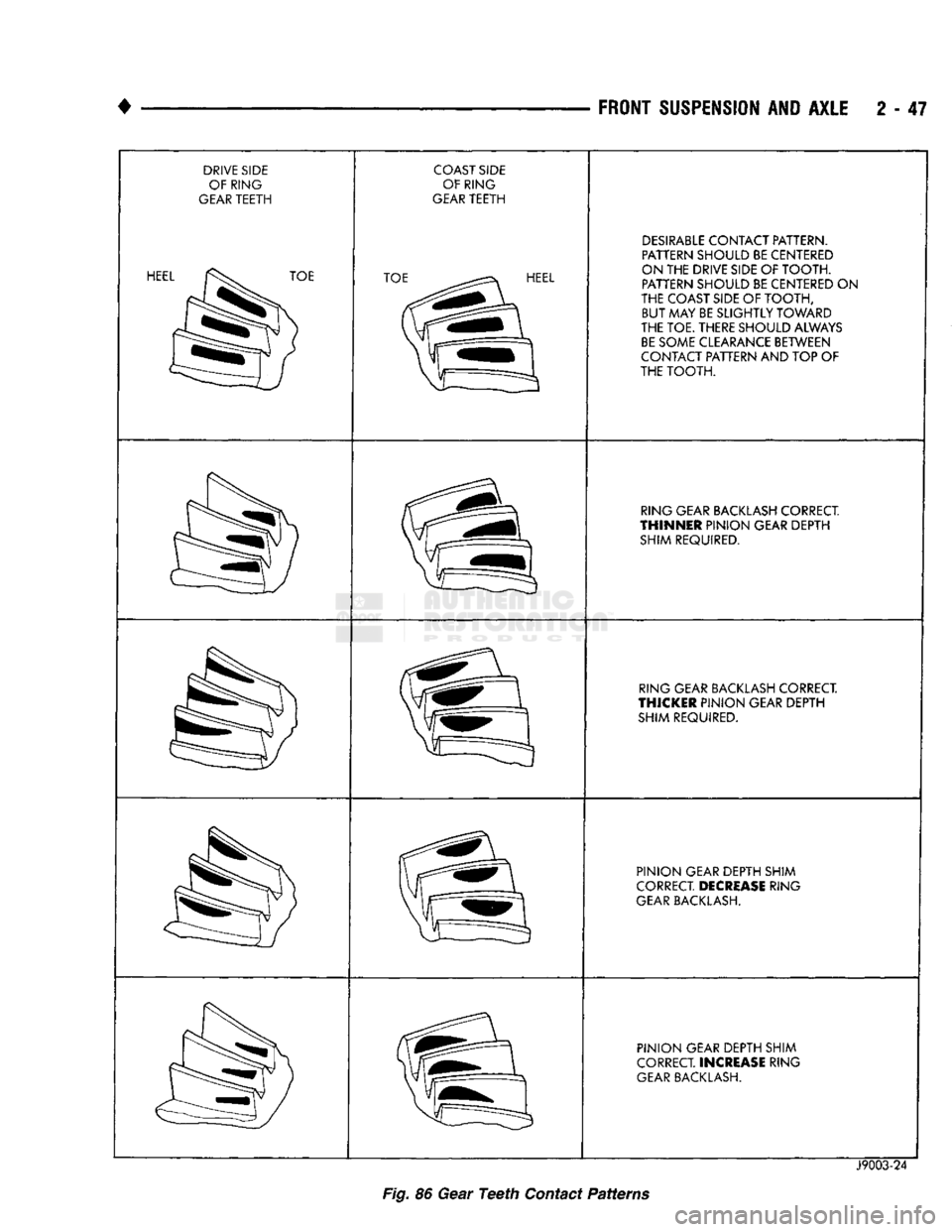
ANALYSIS The ring gear teeth contact patterns will show
if
the pinion gear depth shim(s) have
the
correct thick
ness.
It
will also show
if the
ring gear backlash
has
been adjusted correctly.
The
backlash must
be
main tained within
the
specified limits until
the
correct
teeth contact patterns
are
obtained.
Page 99 of 1502
2
- 46
FRONT
SUSPENSION
AND
AXLE
• (1) Apply a thin coat of hydrated ferric oxide, to
the ring gear teeth. (2) Rotate the ring gear one complete revolution in
both directions while a load is being applied. Insert a
pry bar between the differential housing and the case
flange. This action will produce distinct contact pat
terns on both the drive side and coast side of the ring gear teeth.
(3)
Note patterns in compound. Refer to (Fig. 86)
for interpretation of contact patterns and adjust ac cordingly.
(4) Install the axle shafts. Refer to Axle Shaft In
stallation within this group.
(5)
Install the housing cover. Refill the differential
with lubricant. Refer to Axle Shaft Installation.
Page 100 of 1502
FRONT
SUSPENSION
AND AXLE
2 - 47
DRIVE
SIDE
OF RING
GEAR
TEETH
HEEL
TOE
COAST
SIDE
OF RING
GEAR
TEETH TOE
HEEL
DESIRABLE
CONTACT PATTERN.
PATTERN SHOULD BE CENTERED
ON THE DRIVE SIDE OF TOOTH. PATTERN SHOULD BE CENTERED
ON
THE COAST SIDE OF TOOTH, BUT MAY BE SLIGHTLY TOWARD
THE TOE. THERE SHOULD ALWAYS
BE
SOME CLEARANCE BETWEEN
CONTACT PATTERN AND TOP
OF
THE TOOTH.
RING GEAR
BACKLASH
CORRECT
THINNER
PINION GEAR DEPTH SHIM REQUIRED.
RING GEAR
BACKLASH
CORRECT.
THICKER
PINION GEAR DEPTH
SHIM REQUIRED.
PINION GEAR DEPTH SHIM
CORRECT
DECREASE
RING
GEAR
BACKLASH.
PINION GEAR DEPTH SHIM
CORRECT
INCREASE
RING
GEAR
BACKLASH.
Fig.
86 Gear
Teeth
Contact Patterns
J9003-24