service DODGE TRUCK 1993 Service Repair Manual
[x] Cancel search | Manufacturer: DODGE, Model Year: 1993, Model line: TRUCK, Model: DODGE TRUCK 1993Pages: 1502, PDF Size: 80.97 MB
Page 362 of 1502
*
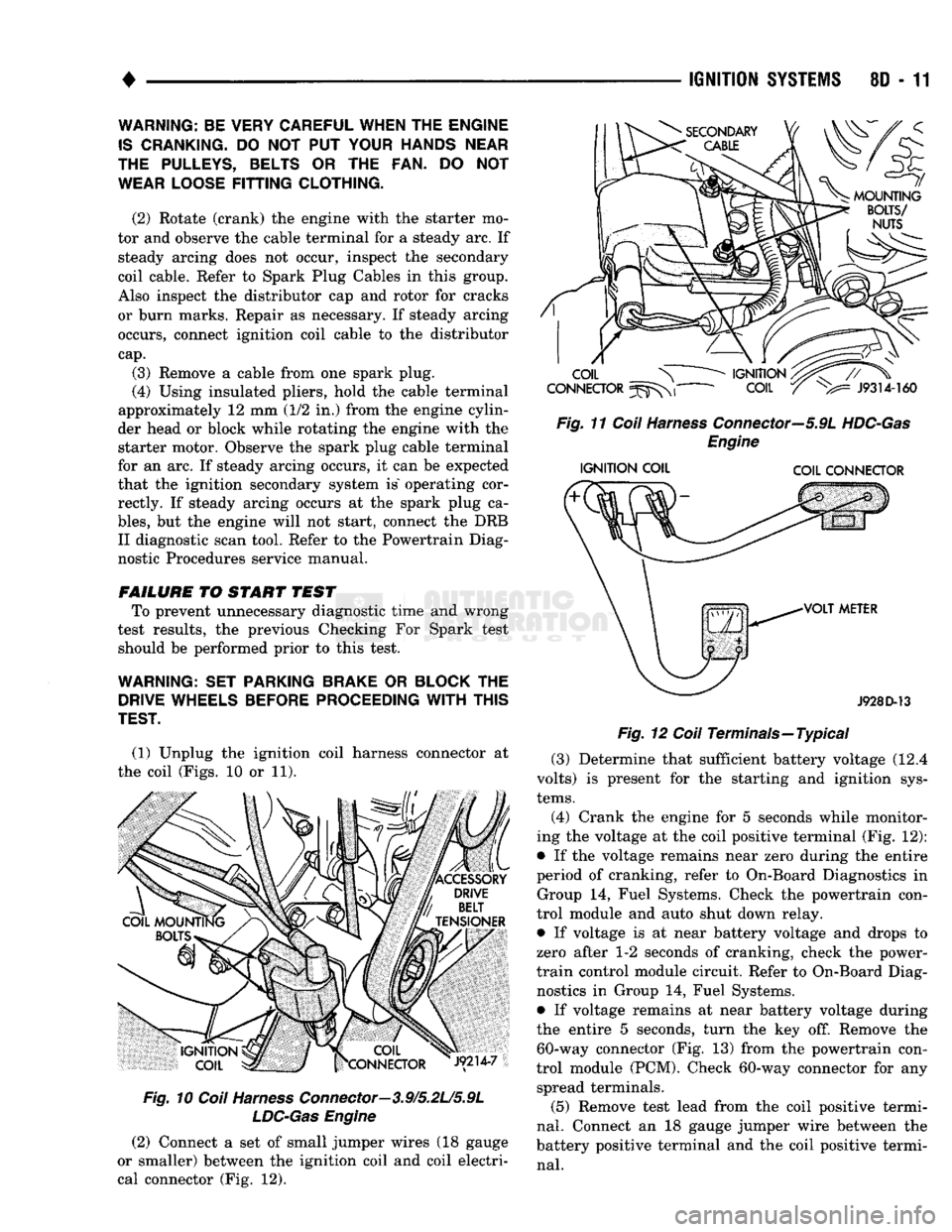
(1) Unplug the ignition coil harness connector at
the coil (Figs. 10 or 11).
Fig.
10
Coil
Harness
Connector—3.9/5.2L/5.9L
LDC-Gas
Engine
(2) Connect a set of small jumper wires (18 gauge
or smaller) between the ignition coil and coil electri
cal connector (Fig. 12).
IGNITION
SYSTEMS
80 - 11
Fig.
11
Coil
Harness
Connector—5.9L
HDC-Gas
Engine
IGNITION
COIL COIL CONNECTOR
J928D-13
Fig.
12
Coil
Terminals—Typical (3) Determine that sufficient battery voltage (12.4
volts) is present for the starting and ignition sys
tems.
(4) Crank the engine for 5 seconds while monitor
ing the voltage at the coil positive terminal (Fig. 12):
• If the voltage remains near zero during the entire
period of cranking, refer to On-Board Diagnostics in Group 14, Fuel Systems. Check the powertrain con
trol module and auto shut down relay.
• If voltage is at near battery voltage and drops to
zero after 1-2 seconds of cranking, check the power-
train control module circuit. Refer to On-Board Diag nostics in Group 14, Fuel Systems.
• If voltage remains at near battery voltage during
the entire 5 seconds, turn the key off. Remove the 60-way connector (Fig. 13) from the powertrain con
trol module (PCM). Check 60-way connector for any spread terminals.
(5) Remove test lead from the coil positive termi
nal.
Connect an 18 gauge jumper wire between the
battery positive terminal and the coil positive termi
nal.
WARNING: BE VERY CAREFUL WHEN THE ENGINE
IS
CRANKING.
DO NOT PUT
YOUR HANDS NEAR
THE PULLEYS, BELTS
OR THE FAN. DO NOT
WEAR LOOSE
FITTING
CLOTHING.
(2) Rotate (crank) the engine with the starter mo
tor and observe the cable terminal for a steady arc. If steady arcing does not occur, inspect the secondary
coil cable. Refer to Spark Plug Cables in this group.
Also inspect the distributor cap and rotor for cracks
or burn marks. Repair as necessary. If steady arcing occurs, connect ignition coil cable to the distributor
cap.
(3) Remove a cable from one spark plug.
(4) Using insulated pliers, hold the cable terminal
approximately 12 mm (1/2 in.) from the engine cylin
der head or block while rotating the engine with the starter motor. Observe the spark plug cable terminal
for an arc. If steady arcing occurs, it can be expected
that the ignition secondary system is" operating cor rectly. If steady arcing occurs at the spark plug ca
bles,
but the engine will not start, connect the DRB II diagnostic scan tool. Refer to the Powertrain Diag
nostic Procedures service manual.
FAILURE
TO START TEST To prevent unnecessary diagnostic time and wrong
test results, the previous Checking For Spark test should be performed prior to this test.
WARNING: SET PARKING BRAKE
OR
BLOCK
THE
DRIVE WHEELS BEFORE PROCEEDING
WITH
THIS
TEST.
Page 363 of 1502
8D
- 12
IGNITION
SYSTEMS
•
XX
oooooooooo
,0000000000
\2141
3%
lOOOOOOOOOO
OOOOOOOOOO
si
20
fcji^OQOOOOOOJ
«r
~
• • -
•
- - #
•oooooooooo.
CONNECTOR
TERMINAL
SIDE
SHOWN
J908D-42
Fig. 13 PCM 60-Way Connector
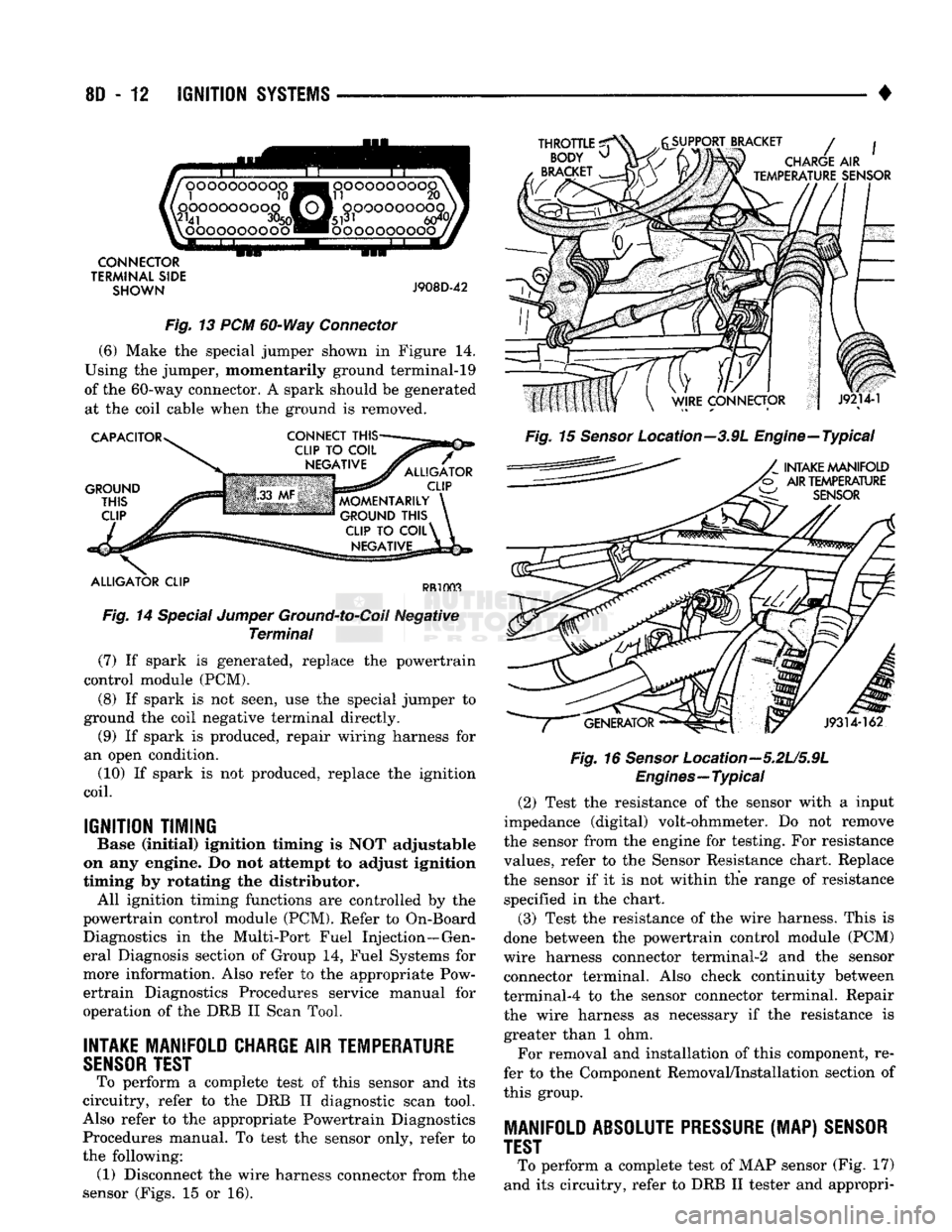
(6) Make the special jumper shown in Figure 14.
Using the jumper, momentarily ground terminal-19
of the 60-way connector. A spark should be generated at the coil cable when the ground is removed.
CAPACITOR
GROUND
THIS
CLIP
CONNECT
THIS-
ALLIGATOR
CLIP
MOMENTARILY
GROUND
THIS
CLIP
TO
COIL^
NEGATIVE
ALLIGATOR
CLIP
PR1003
Fig. 14 Special Jumper Ground-to-Coil Negative Terminal (7) If spark is generated, replace the powertrain
control module (PCM).
(8) If spark is not seen, use the special jumper to
ground the coil negative terminal directly. (9) If spark is produced, repair wiring harness for
an open condition. (10) If spark is not produced, replace the ignition
coil.
IGNITION TIMING
Base (Initial) ignition timing Is NOT adjustable
on any engine. Do not attempt to adjust Ignition
timing by rotating the distributor. All ignition timing functions are controlled by the
powertrain control module (PCM). Refer to On-Board Diagnostics in the Multi-Port Fuel Injection—Gen
eral Diagnosis section of Group 14, Fuel Systems for
more information. Also refer to the appropriate Pow ertrain Diagnostics Procedures service manual for
operation of the DRB II Scan Tool.
INTAKE
MANIFOLD
CHARGE
AIR
TEMPERATURE
SENSOR
TEST
To perform a complete test of this sensor and its
circuitry, refer to the DRB II diagnostic scan tool.
Also refer to the appropriate Powertrain Diagnostics Procedures manual. To test the sensor only, refer to
the following: (1) Disconnect the wire harness connector from the
sensor (Figs. 15 or 16).
THROTTLE
^
BODY
^
BRACKET
SUPPORT BRACKET
/
CHARGE
AIR
TEMPERATURE
SENSOR
Fig. 15 Sensor Location--3.9L Engine—Typical
INTAKE
MANIFOLD
AIR
TEMPERATURE
W
SENSOR
J9314-162
Fig. 16
Sensor
Location—5.2U5.9L
Engines—Typical
(2) Test the resistance of the sensor with a input
impedance (digital) volt-ohmmeter. Do not remove
the sensor from the engine for testing. For resistance
values, refer to the Sensor Resistance chart. Replace
the sensor if it is not within the range of resistance specified in the chart.
(3) Test the resistance of the wire harness. This is
done between the powertrain control module (PCM)
wire harness connector terminal-2 and the sensor connector terminal. Also check continuity between
terminal-4 to the sensor connector terminal. Repair
the wire harness as necessary if the resistance is greater than 1 ohm.
For removal and installation of this component, re
fer to the Component Removal/Installation section of
this group.
MANIFOLD
ABSOLUTE PRESSURE
(MAP)
SENSOR
TEST
To perform a complete test of MAP sensor (Fig. 17)
and its circuitry, refer to DRB II tester and appropri-
Page 365 of 1502
8D
- 14
IGNITION SYSTEMS
• (5) Test the MAP sensor ground circuit at sensor
connector terminal-A (Fig. 19) and PCM connector
terminal-4. Repair the wire harness if necessary.
(6) Test the MAP sensor ground circuit at the
PCM connector between terminal-4 and terminal-11
with an ohmmeter. If the ohmmeter indicates an
open circuit, inspect for a defective sensor ground
connection. Refer to Group 8W, Wiring for location of
this connection. If the ground connection is good, re
place the PCM. If terminal-4 has a short circuit to 12 volts +, correct this condition before replacing the
PCM.
POWERTRAIN
CONTROL MODULE {PCM)
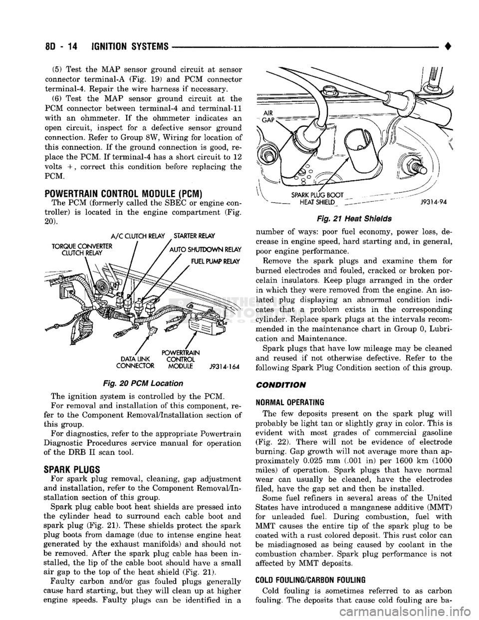
The PCM (formerly called the SBEC or engine -con
troller) is located in the engine compartment (Fig.
20). DATA UNK CONTROL
CONNECTOR MODULE
J9314-164
Fig.
20 PCM Location The ignition system is controlled by the PCM.
For removal and installation of this component, re
fer to the Component Removal/Installation section of
this group.
For diagnostics, refer to the appropriate Powertrain
Diagnostic Procedures service manual for operation
of the DRB II scan tool.
SPARK
PLUGS
For spark plug removal, cleaning, gap adjustment
and installation, refer to the Component Removal/In
stallation section of this group. Spark plug cable boot heat shields are pressed into
the cylinder head to surround each cable boot and
spark plug (Fig. 21). These shields protect the spark
plug boots from damage (due to intense engine heat
generated by the exhaust manifolds) and should not
be removed. After the spark plug cable has been in stalled, the lip of the cable boot should have a small
air gap to the top of the heat shield (Fig. 21). Faulty carbon and/or gas fouled plugs generally
cause hard starting, but they will clean up at higher
engine speeds. Faulty plugs can be identified in a
Fig.
21 Heat
Shields
number of ways: poor fuel economy, power loss, de
crease in engine speed, hard starting and, in general,
poor engine performance.
Remove the spark plugs and examine them for
burned electrodes and fouled, cracked or broken por celain insulators. Keep plugs arranged in the order
in which they were removed from the engine. An iso
lated plug displaying an abnormal condition indi
cates that a problem exists in the corresponding
cylinder. Replace spark plugs at the intervals recom
mended in the maintenance chart in Group 0, Lubri
cation and Maintenance.
Spark plugs that have low mileage may be cleaned
and reused if not otherwise defective. Refer to the
following Spark Plug Condition section of this group.
CONDITION
NORMAL OPERATING
The few deposits present on the spark plug will
probably be light tan or slightly gray in color. This is evident with most grades of commercial gasoline (Fig. 22). There will not be evidence of electrode
burning. Gap growth will not average more than ap proximately 0.025 mm (.001 in) per 1600 km (1000
miles) of operation. Spark plugs that have normal
wear can usually be cleaned, have the electrodes filed, have the gap set and then be installed.
Some fuel refiners in several areas of the United
States have introduced a manganese additive (MMT)
for unleaded fuel. During combustion, fuel with
MMT causes the entire tip of the spark plug to be coated with a rust colored deposit. This rust color can
be misdiagnosed as being caused by coolant in the combustion chamber. Spark plug performance is not affected by MMT deposits.
COLD
FOULING/CARBON FOULING
Cold fouling is sometimes referred to as carbon
fouling. The deposits that cause cold fouling are ba-
Page 367 of 1502
8D
- 16
IGNITION
SYSTEMS
• other operating conditions are causing engine over
heating. (The heat range rating refers to the operat
ing temperature of a particular type spark plug.
Spark plugs are designed to operate within specific
temperature ranges. This depends upon the thickness and length of the center electrodes porcelain insula
tor.)
GROUND
ELECTRODE
CENTER
ELECTRODE
DISSOLVED
J908D-14 Fig. 26 Preignition Damage
SPARK
PLUG
OVERHEATING
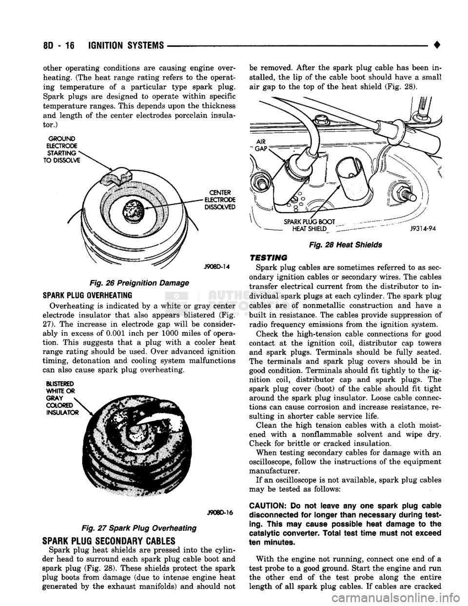
Overheating is indicated by a white or gray center
electrode insulator that also appears blistered (Fig.
27).
The increase in electrode gap will be consider
ably in excess of 0.001 inch per 1000 miles of opera
tion. This suggests that a plug with a cooler heat
range rating should be used. Over advanced ignition
timing, detonation and cooling system malfunctions can also cause spark plug overheating.
BLISTERED
WHITE
OR
J908D-16
Fig. 27 Spark Plug Overheating
SPARK
PLUG
SECONDARY
CABLES
Spark plug heat shields are pressed into the cylin
der head to surround each spark plug cable boot and spark plug (Fig. 28). These shields protect the spark
plug boots from damage (due to intense engine heat
generated by the exhaust manifolds) and should not be removed. After the spark plug cable has been in
stalled, the lip of the cable boot should have a small
air gap to the top of the heat shield (Fig. 28).
Fig.
28 Heat
Shields
TESTING
Spark plug cables are sometimes referred to as sec
ondary ignition cables or secondary wires. The cables
transfer electrical current from the distributor to in dividual spark plugs at each cylinder. The spark plug
cables are of nonmetallic construction and have a
built in resistance. The cables provide suppression of radio frequency emissions from the ignition system.
Check the high-tension cable connections for good
contact at the ignition coil, distributor cap towers and spark plugs. Terminals should be fully seated.
The terminals and spark plug covers should be in good condition. Terminals should fit tightly to the ig
nition coil, distributor cap and spark plugs. The spark plug cover (boot) of the cable should fit tight
around the spark plug insulator. Loose cable connec
tions can cause corrosion and increase resistance, re sulting in shorter cable service life. Clean the high tension cables with a cloth moist
ened with a nonflammable solvent and wipe dry.
Check for brittle or cracked insulation. When testing secondary cables for damage with an
oscilloscope, follow the instructions of the equipment
manufacturer. If an oscilloscope is not available, spark plug cables
may be tested as follows:
CAUTION:
Do not leave any one
spark
plug
cable
disconnected
for
longer
than
necessary
during test
ing.
This
may
cause
possible
heat
damage
to the
catalytic converter. Total test
time
must
not exceed
ten
minutes.
With the engine not running, connect one end of a
test probe to a good ground. Start the engine and run the other end of the test probe along the entire length of all spark plug cables. If cables are cracked
Page 369 of 1502
8D
- 18
IGNITION
SYSTEMS
•
COMPONENT REMGWAL/INSTALLATION
INDEX
page
Automatic
Shut Down (ASD) Relay
18
Camshaft
Position
Sensor
, 18
Crankshaft Position
Sensor
18
Distributor
Service
20
Engine
Coolant Temperature
Sensor
20
General
Information
18
Ignition
Coil
21
page
Intake
Manifold Charge
Air
Temperature
Sensor
. 22
Manifold Absolute Pressure (MAP)
Sensor
..... 22
Oxygen
(02)
Sensor
22
Powertrain
Control
Module (PCM)
22
Spark
Plug Secondary Cables
24
Spark
Plugs
23
Throttle
Position
Sensor
(TPS)
24
GENERAL
INFORMATION
This section
of the
group, Component Removal/In
stallation, will discuss
the
removal
and
installation
of ignition system components. For basic ignition system diagnostics
and
service
adjustments, refer
to the
Diagnostics/Service Proce
dures section
of
this group. For system operation
and
component identification,
refer
to the
Component Identification/System Opera
tion section
of
this group.
AUTOMATIC
SHUT DOWN
(ASb)
RELAY
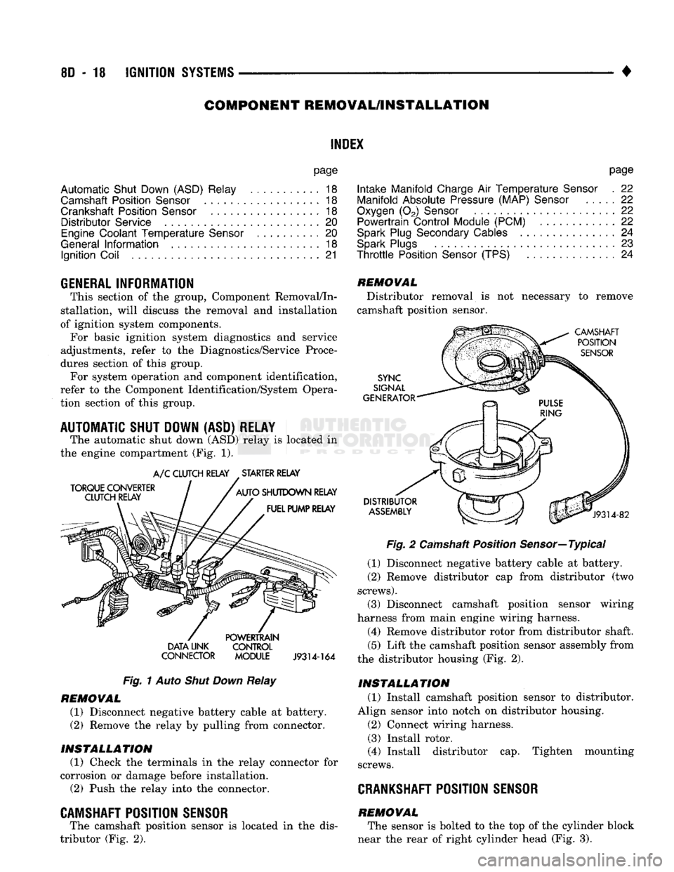
The automatic shut down
(ASD)
relay
is
located
in
the engine compartment
(Fig. 1).
TORQUE CONVERTER
CLUTCH RELAY
A/C
CLUTCH RELAY STARTER RELAY
AUTO
SHUTDOWN RELAY FUEL PUMP RELAY DATA UNK
CONNECTOR POWERTRAIN
CONTROL
MODULE
J9314-164
Fig.
1
Auto
Shut Down
Relay
REMOVAL
(1) Disconnect negative battery cable
at
battery.
(2)
Remove
the
relay
by
pulling from connector.
INSTALLATION
(1) Check
the
terminals
in the
relay connector
for
corrosion
or
damage before installation.
(2)
Push
the
relay into
the
connector.
CAMSHAFT POSITION SENSOR
The camshaft position sensor
is
located
in the
dis
tributor
(Fig. 2).
REMOVAL
Distributor removal
is not
necessary
to
remove
camshaft position sensor.
CAMSHAFT POSITION
SENSOR
SYNC
SIGNAL
GENERATOR
DISTRIBUTOR
ASSEMBLY
J9314-82
Fig.
2
Camshaft Position Sensor—Typical
(1) Disconnect negative battery cable
at
battery.
(2)
Remove distributor
cap
from distributor
(two
screws).
(3) Disconnect camshaft position sensor wiring
harness from main engine wiring harness.
(4) Remove distributor rotor from distributor shaft.
(5)
Lift
the
camshaft position sensor assembly from
the distributor housing
(Fig. 2).
INSTALLATION
(1) Install camshaft position sensor
to
distributor.
Align sensor into notch
on
distributor housing.
(2)
Connect wiring harness.
(3) Install rotor.
(4) Install distributor
cap.
Tighten mounting
screws.
CRANKSHAFT
POSITION SENSOR
REMOVAL The sensor
is
bolted
to the top of the
cylinder block
near
the
rear
of
right cylinder head
(Fig. 3).
Page 371 of 1502
8D
- 20
IGNITION
SYSTEMS
•
ENGINE
COOLANT
TEMPERATURE
SENSOR
WARNING: HOT, PRESSURIZED COOLANT CAN CAUSE INJURY BY SCALDING. COOLING SYSTEM MUST BE PARTIALLY DRAINED BEFORE REMOV
ING THE COOLANT TEMPERATURE SENSOR. RE
FER TO GROUP 7, COOLING.
REMOVAL
(1) Partially drain cooling system. Refer to Group
7, Cooling.
(2)
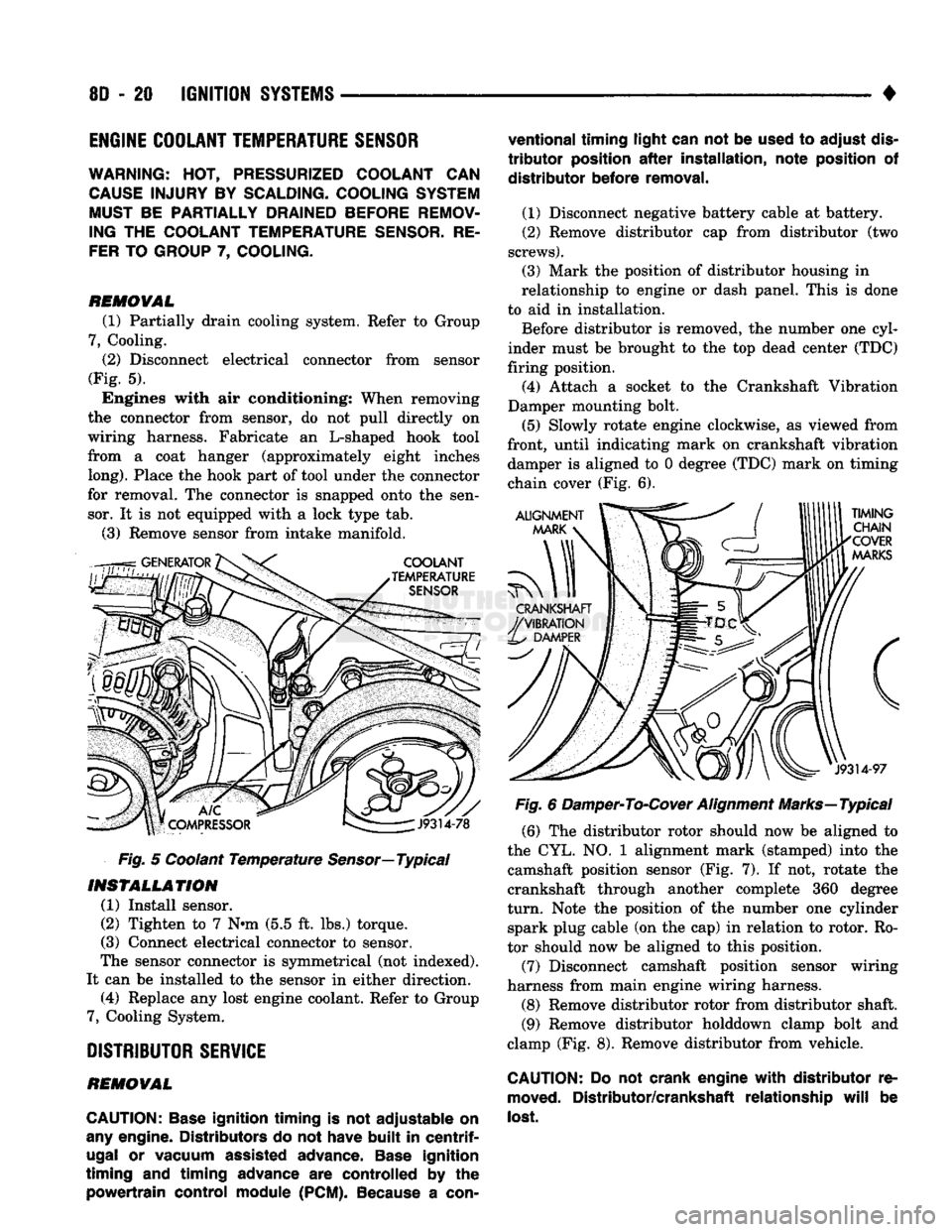
Disconnect electrical connector from sensor
(Fig. 5). Engines with air conditioning: When removing
the connector from sensor, do not pull directly on
wiring harness. Fabricate an L-shaped hook tool
from a coat hanger (approximately eight inches
long).
Place the hook part of tool under the connector
for removal. The connector is snapped onto the sen sor. It is not equipped with a lock type tab.
(3) Remove sensor from intake manifold.
Fig. 5 Coolant Temperature
Sensor—
Typical
INSTALLATION
(1) Install sensor.
(2) Tighten to 7 Nnn (5.5 ft. lbs.) torque.
(3) Connect electrical connector to sensor.
The sensor connector is symmetrical (not indexed).
It can be installed to the sensor in either direction. (4) Replace any lost engine coolant. Refer to Group
7, Cooling System.
DISTRIBUTOR
SERVICE
REMOVAL
CAUTION:
Base
ignition timing
is not
adjustable
on
any
engine. Distributors
do not
have
built
in
centrif
ugal
or
vacuum assisted advance.
Base
ignition
timing
and
timing advance
are
controlled
by the
powertrain control module
(PCM).
Because
a
con
ventional timing light can
not be
used
to
adjust
dis
tributor
position
after
installation, note position
of
distributor before removal.
(1) Disconnect negative battery cable at battery.
(2) Remove distributor cap from distributor (two
screws).
(3) Mark the position of distributor housing in
relationship to engine or dash panel. This is done
to aid in installation. Before distributor is removed, the number one cyl
inder must be brought to the top dead center (TDC)
firing position. (4) Attach a socket to the Crankshaft Vibration
Damper mounting bolt.
(5) Slowly rotate engine clockwise, as viewed from
front, until indicating mark on crankshaft vibration damper is aligned to 0 degree (TDC) mark on timing
chain cover (Fig. 6).
Fig. 6 Damper-To-Cover Alignment Marks—Typical (6) The distributor rotor should now be aligned to
the CYL. NO. 1 alignment mark (stamped) into the camshaft position sensor (Fig. 7). If not, rotate the
crankshaft through another complete 360 degree
turn.
Note the position of the number one cylinder spark plug cable (on the cap) in relation to rotor. Ro
tor should now be aligned to this position.
(7) Disconnect camshaft position sensor wiring
harness from main engine wiring harness.
(8) Remove distributor rotor from distributor shaft. (9) Remove distributor holddown clamp bolt and
clamp (Fig. 8). Remove distributor from vehicle.
CAUTION: Do not
crank engine
with
distributor
re
moved.
Distributor/crankshaft relationship
will
be
lost.
Page 374 of 1502
•
IGNITION
SYSTEMS
80 - 23
PCM
MOUNTING
PCM CONNECTOR CONNECTOR
MOUNTING
BOLT
J9314-165
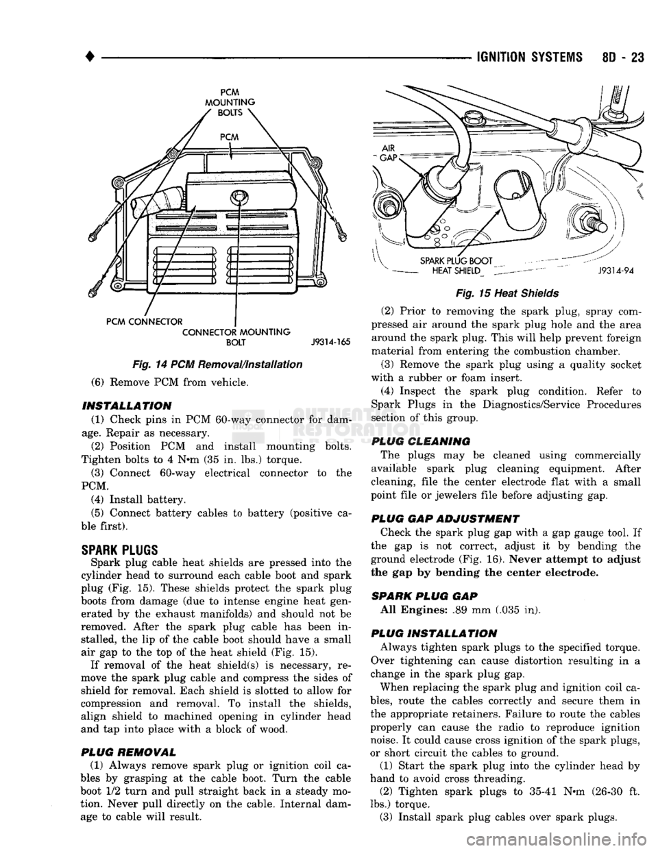
Fig.
14 PCM Removal/Installation
(6) Remove PCM from vehicle.
INSTALLATION
(1) Check pins in PCM 60-way connector for dam
age.
Repair as necessary. (2) Position PCM and install mounting bolts.
Tighten bolts to 4 N»m (35 in. lbs.) torque. (3) Connect 60-way electrical connector to the
PCM. (4) Install battery.
(5) Connect battery cables to battery (positive ca
ble first).
SPARK
PLUGS
Spark plug cable heat shields are pressed into the
cylinder head to surround each cable boot and spark
plug (Fig. 15). These shields protect the spark plug
boots from damage (due to intense engine heat gen erated by the exhaust manifolds) and should not be
removed. After the spark plug cable has been in stalled, the lip of the cable boot should have a small
air gap to the top of the heat shield (Fig. 15). If removal of the heat shield(s) is necessary, re
move the spark plug cable and compress the sides of
shield for removal. Each shield is slotted to allow for
compression and removal. To install the shields, align shield to machined opening in cylinder head
and tap into place with a block of wood.
PLUG
REMOVAL
(1) Always remove spark plug or ignition coil ca
bles by grasping at the cable boot. Turn the cable
boot 1/2 turn and pull straight back in a steady mo
tion. Never pull directly on the cable. Internal dam age to cable will result.
Fig.
15 Heat
Shields
(2) Prior to removing the spark plug, spray com
pressed air around the spark plug hole and the area around the spark plug. This will help prevent foreign
material from entering the combustion chamber.
(3) Remove the spark plug using a quality socket
with a rubber or foam insert. (4) Inspect the spark plug condition. Refer to
Spark Plugs in the Diagnostics/Service Procedures
section of this group.
PLUG CLEANING The plugs may be cleaned using commercially
available spark plug cleaning equipment. After
cleaning, file the center electrode flat with a small
point file or jewelers file before adjusting gap.
PLUG GAP ADJUSTMENT Check the spark plug gap with a gap gauge tool. If
the gap is not correct, adjust it by bending the
ground electrode (Fig. 16). Never attempt to adjust
the gap by bending the center electrode.
SPARK
PLUG
GAP All Engines: .89 mm (.035 in).
PLUG INSTALLATION Always tighten spark plugs to the specified torque.
Over tightening can cause distortion resulting in a
change in the spark plug gap.
When replacing the spark plug and ignition coil ca
bles,
route the cables correctly and secure them in
the appropriate retainers. Failure to route the cables
properly can cause the radio to reproduce ignition noise. It could cause cross ignition of the spark plugs,
or short circuit the cables to ground.
(1) Start the spark plug into the cylinder head by
hand to avoid cross threading. (2) Tighten spark plugs to 35-41 N-m (26-30 ft.
lbs.) torque. (3) Install spark plug cables over spark plugs.
Page 376 of 1502
IGNITION
SYSTEMS
80 - 25
IGNITION
SWITCH
INDEX
General
Information
page
. . 25
GENERAL
INFORMATION
The ignition switch is located in the steering col
umn. The Key-In-Switch and Halo Light are integral
with the ignition switch. Refer to Group 8M for Key- In-Switch and Halo Light diagnosis.
IGNITION
SWITCH
AND
KEY
CYLINDER
SERVICE
REMOVAL
(1) Disconnect negative battery cable.
(2) Tilt column: Remove tilt lever (counterclock
wise).
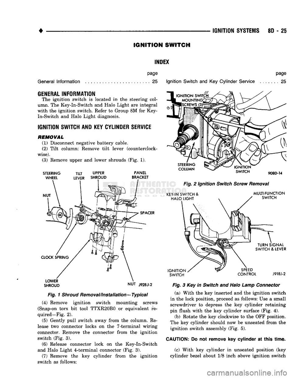
(3) Remove upper and lower shrouds (Fig. 1).
STEERING
WHEEL
NUT
TILT
UPPER
LEVER SHROUD PANEL
BRACKET
SPACER
CLOCK SPRING LOWER
SHROUD NUT
J928J-2
Fig.
1
Shroud
Removal/Installation—Typical (4) Remove ignition switch mounting screws
(Snap-on torx bit tool TTXR20B0 or equivalent re
quired—Fig. 2).
(5) Gently pull switch away from the column. Re
lease two connector locks on the 7-terminal wiring
connector. Remove the connector from the ignition switch (Fig. 3).
(6) Release connector lock on the Key-In-Switch
and Halo Light 4-terminal connector (Fig. 3).
(7) Remove the key cylinder from the ignition
switch as follows:
Ignition
Switch
and Key
Cylinder
Service
page
. . 25
STEERING
COLUMN
IGNITION
SWITCH
908D-14
Fig.
2 Ignition
Switch
Screw
Removal
KEY-IN SWITCH &
HALO
LIGHT
MULTIFUNCTION
SWITCH
IGNITION
SWITCH
TURN
SIGNAL
SWITCH & LEVER
SPEED
CONTROL
J918J-2
Fig.
3 Key in
Switch
and Halo
Lamp
Connector
(a) With the key inserted and the ignition switch
in the lock position, proceed as follows: Use a small screwdriver to depress the key cylinder retaining
pin flush with the key cylinder surface (Fig. 4).
(b) Rotate the key clockwise to the OFF position.
The key cylinder should now be unseated from the ignition switch assembly (Fig. 5).
CAUTION:
Do not
remove
key
cylinder
at
this
time.
(c) With key cylinder in unseated position (key
cylinder bezel about 1/8 inch above ignition switch
Page 379 of 1502
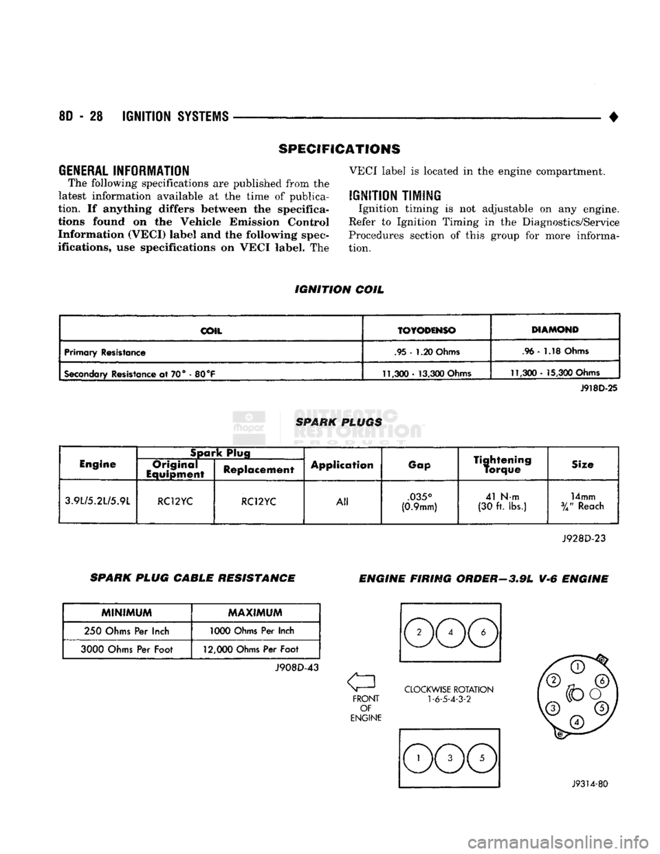
8D
- 28
IGNITION
SYSTEMS
•
GENERAL
INFORMATION
The following specifications
are
published from
the
latest information available
at the
time
of
publica
tion.
If
anything differs between
the
specifica
tions found
on the
Vehicle Emission Control Information (VECI) label
and the
following spec
ifications,
use
specifications
on
VECI label.
The
SPECIFICATIONS
VECI label
is
located
in the
engine compartment.
IGNITION
TIMING
Ignition timing
is not
adjustable
on any
engine.
Refer
to
Ignition Timing
in the
Diagnostics/Service
Procedures section
of
this group
for
more informa
tion.
IGNITION
COIL
COii
TOYODSNSO
Primary Resistance .95-
1.20
Ohms .96-
1.18
Ohms
Secondary
Resistance
at
70°
-
80
°F
11,300-
13,300
Ohms
11,300
-
15,300
Ohms
SPARK PLUGS J918D-25
Engine
Spark
Plug
Application
Gap
Tightening
Torque Size
Engine
Original
Equipment Replacement Application
Gap
Tightening
Torque Size
3.9L/5.2L/5.9L
RC12YC RC12YC
All
.035°
(0.9mm)
41
Nm
(30
ft.
lbs.)
14mm
%"
Reach
J928D-23
SPARK PLUG CABLE RESISTANCE
ENGINE FIRING ORDER-3.9L
V-6
ENGINE
MINIMUM
MAXIMUM
250 Ohms
Per
Inch 1000 Ohms
Per
Inch
3000
Ohms
Per
Foot
12,000
Ohms
Per
Foot
J908D-43
a
FRONT
OF
ENGINE CLOCKWISE
ROTATION
1
-6-5-4-3-2
,
©
V©
^ ©y
©
J9314-80
Page 382 of 1502

• • ^ ^ ^ INSTRUMENT PANEL AND GAUGES 8E - 1
CONTENTS
page
CLUSTER AND GAUGE SERVICE PROCEDURES . 12
CLUSTER AND GAUGE TEST PROCEDURES .. i
GENERAL INFORMATION . 1
page
MESSAGE CENTER-DIESEL ENGINE ........ 4
MESSAGE CENTER-GAS ENGINE .......... 3
SWITCH
AND PANEL COMPONENT SERVICE . 16
GENERAL
INFORMATION
INDEX
page
Generator
Indicating
System
2
Distance
Sensor
2
Electronic
Digital
Clock
3
Fuel
Level
Indicating
System
1
page
Malfunction
Indicator
(Check
Engine)
3
Oil
Pressure
Warning
Lamp
................. 2
Speedometer/Odometer
System
2
Temperature
and Oil
Indicating
System
......... 2
D-body trucks have an instrument cluster which
includes gauges for fuel level, coolant temperature,
oil pressure, and charging system voltage (Fig. 1).
When the ignition switch is in the OFF position all
the gauges will show a reading except the voltage gauge. However, the readings are only accurate
when the ignition switch is in the ON position.
The cluster also includes warning lamps for:
• seat belt warning
• low oil pressure
• high beam
• left and right turn signals
• check engine. J908E-66
Fig.
11nstrument
Cluster
FUEL LEVEL INDICATING SYSTEM (FIG. 2)
A hinged float arm in the fuel tank raises or lowers
depending on the fuel level. The float arm contacts a
variable resistor in the gauge sending unit. This pro
vides a change of resistance in the fuel gauge circuit
with any up or down movement of the float. This sender
resistance is shown as fuel level on the gauge. Resistance is greatest when the fuel level in the
tank is low and the float arm drops. With high resis
tance current flow is low and consequently positions
the instrument panel gauge pointer to low.
Resistance in the circuit is at a minimum when the
tank is full and the float arm is raised. With resis
tance at a minimum, current flow is high registering
full on the instrument panel gauge.
12
VOLTS
TO
GAUGE
IP
FUEL
TANK
SENDING
UNIT
FLOAT
SENDING
UNIT
1:
1
j
^
fCONNECTOR
!g|yj-»—
FUEL
GAUGE
FUEL
TANK
J098E-47
Fig.
2
Fuel
Level
Indicating
System
INSTRUMENT PANEL AND GAUGES