service DODGE TRUCK 1993 Service Owners Manual
[x] Cancel search | Manufacturer: DODGE, Model Year: 1993, Model line: TRUCK, Model: DODGE TRUCK 1993Pages: 1502, PDF Size: 80.97 MB
Page 323 of 1502
8A
- 2
ELECTRICAL
•
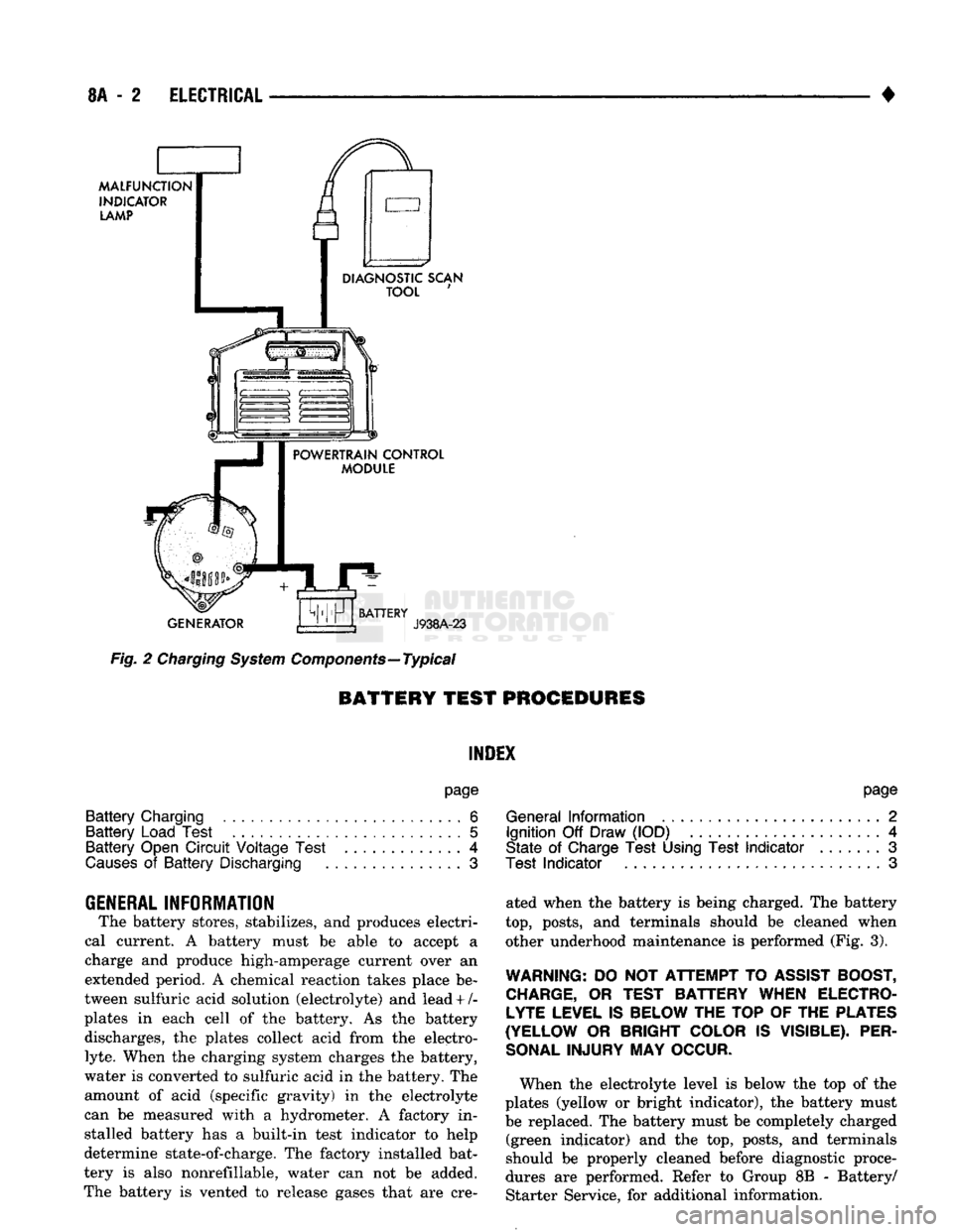
MALFUNCTION
INDICATOR
LAMP
DIAGNOSTIC SCAN
TOOL
POWERTRAIN CONTROL
MODULE
GENERATOR
BATTERY
J938A-23
Fig.
2
Charging
System
Components—Typical
BATTERY TEST
PROCEDURES
INDEX
page
Battery
Charging
6
Battery
Load Test
5
Battery
Open
Circuit
Voltage Test
.............
4
Causes
of
Battery
Discharging
3
GENERAL
INFORMATION
The battery stores, stabilizes,
and
produces electri
cal current.
A
battery must
be
able
to
accept
a
charge
and
produce high-amperage current over
an
extended period.
A
chemical reaction takes place
be
tween sulfuric acid solution (electrolyte)
and
lead + /-
plates
in
each cell
of the
battery.
As the
battery discharges,
the
plates collect acid from
the
electro
lyte.
When
the
charging system charges
the
battery,
water
is
converted
to
sulfuric acid
in the
battery.
The
amount
of
acid (specific gravity)
in the
electrolyte
can
be
measured with
a
hydrometer.
A
factory
in
stalled battery
has a
built-in test indicator
to
help
determine state-of-charge.
The
factory installed bat
tery
is
also nonrefillable, water
can not be
added.
The battery
is
vented
to
release gases that
are cre-
page
General
Information
2
Ignition
Off
Draw (IOD)
4
State
of
Charge Test Using Test
Indicator
.......
3
Test
Indicator
3
ated when
the
battery
is
being charged.
The
battery
top,
posts,
and
terminals should
be
cleaned when other underhood maintenance
is
performed (Fig.
3).
WARNING:
DO
NOT
ATTEMPT
TO
ASSIST BOOST, CHARGE,
OR
TEST BATTERY WHEN ELECTROLYTE LEVEL IS BELOW THE TOP
OF
THE PLATES
(YELLOW
OR
BRIGHT COLOR
IS
VISIBLE). PER
SONAL
INJURY
MAY
OCCUR.
When
the
electrolyte level
is
below
the top of the
plates (yellow
or
bright indicator),
the
battery must
be replaced.
The
battery must
be
completely charged (green indicator)
and the top,
posts,
and
terminals
should
be
properly cleaned before diagnostic proce
dures
are
performed. Refer
to
Group
8B -
Battery/ Starter Service,
for
additional information.
Page 325 of 1502
8A
- 4
ELECTRICAL
•
IGNITION
OFF
DRAW
(IOD)
Ignition off draw refers to power being drained
from the battery with the ignition turned off. A nor
mal vehicle electrical system will draw from 5 to 20
milliamps. A vehicle that has not been operated for
an extended period of time (approximately 20 days)
may discharge the battery to an inadequate level.
Battery drain should not exceed approximately 20
MA (20 milliamps = 0.020 amps). The 20 MA are needed to supply PCM memory,
digital clock memory, and ETR (electronically tuned
radio) memory. Excessive battery drain is caused by items left
turned on, internally shorted generator, or intermit
tent short in wiring.
If the IOD is excessive (over 20 milliamperes), the
defect must be found and corrected before replacing a
battery. In most cases the battery can be charged and returned to service.
TEST PROCEDURE Testing for higher amperage IOD must be per
formed first to prevent damage to most milliamp
meters.
Verify that all electrical accessories are OFF. Turn
off all lights, remove ignition key, and close all
doors.
If the vehicle is equipped with electronic acces
sories (illuminated entry, high line radio), allow the
systems to automatically shut off (time out), up to 3
minutes.
(1) After determining that the underhood lamp is
operating properly then disconnect bulb. (2) Disconnect negative cable from battery.
(3) Connect a typical 12 volt test light (low watt
age bulb) between the negative cable clamp and the
battery negative terminal. The test light may light brightly for up to 3 min
utes or may not light at all (depending on the elec
trical equipment). The term brightly being used
throughout the following tests, implies the bright ness of the test light will be the same as if it were
connected across the battery.
The test light must be securely clamped to the neg
ative cable and battery terminal. If the test light be
comes disconnected during any of the IOD test, the electronic timer function will be activated and all
tests must be repeated.
(4) After 3 minutes, the test light should turn OFF
or be DIMLY lit (depending on the electrical equip
ment).
If the test light remains brightly lit do not
disconnect it. Remove each fuse or circuit breaker (refer to Group 8 - Wiring Diagrams) until test light
is either OFF or DIMLY lit. This will eliminate the
higher amperage draw.
If test light is still bright after disconnecting each
fuse and circuit breaker, disconnect the wiring har ness from the generator. Refer to Generator Testing
in this group. Do not disconnect the test light. After higher amperage IOD has been corrected, low
amperage IOD may be checked.
It is now safe to install milliamp meter to check for
low amperage IOD.
(5) With test light still connected, securely clamp
an ammeter between battery negative terminal and
negative battery cable.
If the test light or the milliamp meter circuit is
broken the various timer circuits will start. Do
not open any doors or turn on any electrical ac cessories with the test light disconnected or the
meter may be damaged.
(6) Disconnect test light. The current draw should
not exceed 0.020 amp. If it exceeds 20 milliamps iso
late each circuit by removing circuit breakers and
fuses.
The meter reading drops once the high current
problem is found. Repair this section of the circuit,
whether it is a wiring short or component failure.
BATTERY
OPEN CIRCUIT VOLTAGE TEST
A battery voltage (no load) test will indicate the
state of charge of a battery that will pass the Battery
Load Test described in this section. Before proceed
ing with this test or the Battery Load Test the
battery must be completely charged as de scribed in Battery Charging in this section. If a battery has a no load voltage reading of 12.4
volts or greater but will not endure a load test, it is
defective and should be replaced. Refer to Group 8B,
Battery/Starter Service for instructions. To test bat
tery no load voltage, perform the following operation: (1) Before measuring open circuit voltage, the sur
face charge must be removed from plates. Turn head lights on for 15 seconds then allow up to 5 minutes
for voltage to stabilize. (2) Remove both battery cables, negative first.
(3) Using a voltmeter connected to the battery
posts,
see instructions provided with voltmeter, mea sure open circuit voltage (Fig. 6). This voltage reading will indicate state of charge,
but will not reveal cranking capacity. Refer to Bat
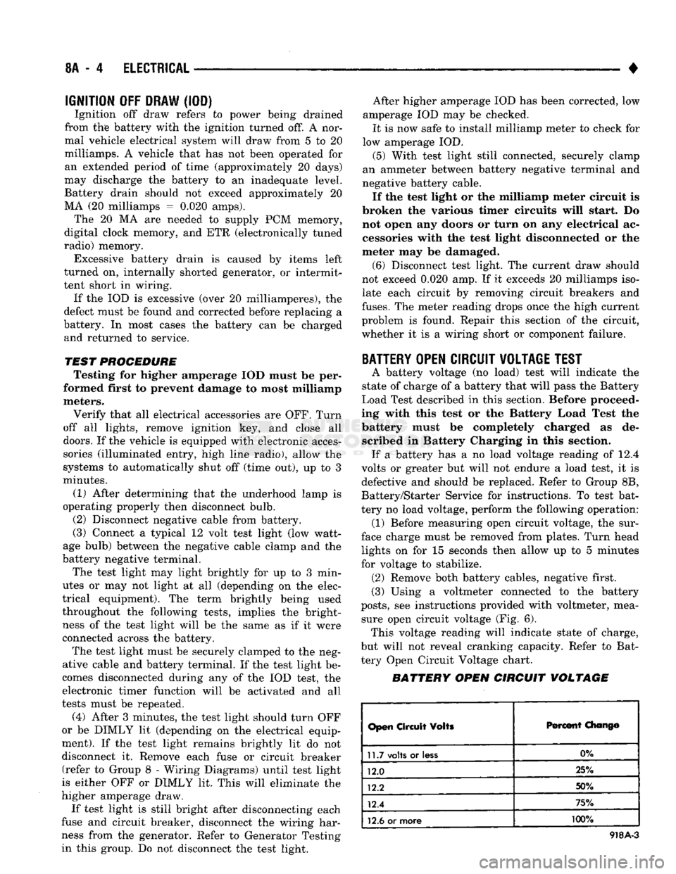
tery Open Circuit Voltage chart.
BATTERY OPEN CIRCUIT VOLTAGE
Open
Circuit
Volts
Percent
Chang©
11.7
volts
or
less
0%
12.0 25%
12.2 50%
12.4 75%
12.6
or more 100%
918A-3
Page 327 of 1502
8A
- 6
ELECTRICAL
•
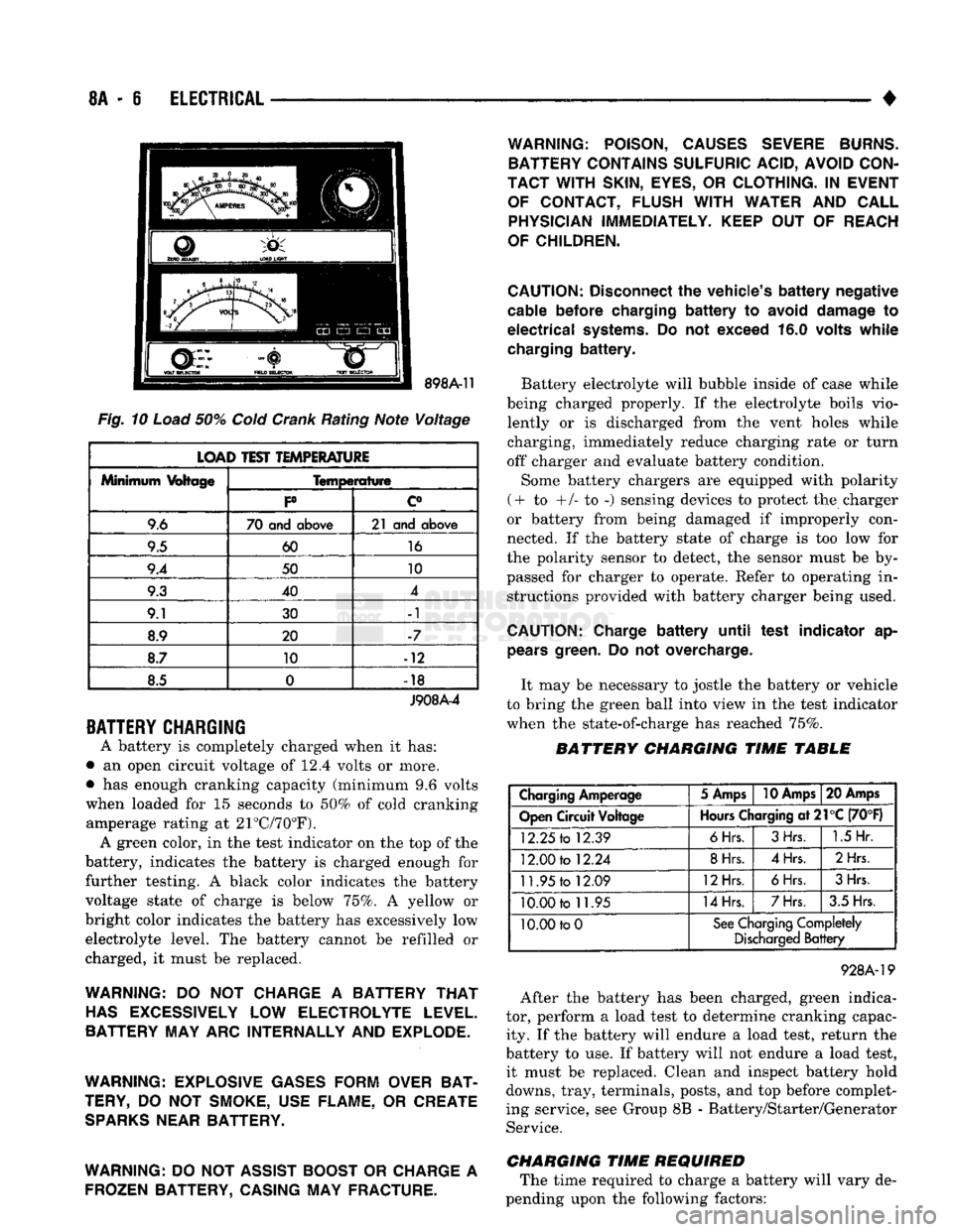
Fig.
10
Load
50%
Cold
Crank
Rating Note Voltage
LOAD TEST TEMPERATURE
Minimum
Voltage
Temperature
Minimum
Voltage
P c°
9.6 70 and
above
21 and
above
9.5 60
16
9.4 50 10
9.3 40 4
9.1 30 -1
8.9 20 -7
8.7 10 -12
8.5 0
•
18
J908A-4
BATTERY
CHARGING
A battery is completely charged when it has:
• an open circuit voltage of 12.4 volts or more.
• has enough cranking capacity (minimum 9.6 volts
when loaded for 15 seconds to 50% of cold cranking amperage rating at 21°C/70°F). A green color, in the test indicator on the top of the
battery, indicates the battery is charged enough for
further testing. A black color indicates the battery
voltage state of charge is below 75%. A yellow or
bright color indicates the battery has excessively low electrolyte level. The battery cannot be refilled or
charged, it must be replaced.
WARNING:
DO NOT
CHARGE
A
BATTERY
THAT
HAS
EXCESSIVELY
LOW
ELECTROLYTE LEVEL.
BATTERY MAY ARC INTERNALLY AND EXPLODE.
WARNING: EXPLOSIVE GASES FORM OVER BAT
TERY,
DO NOT
SMOKE, USE FLAME,
OR
CREATE
SPARKS
NEAR BATTERY.
WARNING:
DO
NOT ASSIST BOOST
OR
CHARGE
A
FROZEN BATTERY, CASING MAY FRACTURE. WARNING: POISON, CAUSES SEVERE BURNS.
BATTERY CONTAINS SULFURIC ACID, AVOID CON
TACT WITH
SKIN,
EYES,
OR
CLOTHING.
IN
EVENT OF CONTACT, FLUSH
WITH
WATER
AND
CALL PHYSICIAN IMMEDIATELY. KEEP
OUT OF
REACH
OF CHILDREN.
CAUTION:
Disconnect
the
vehicle's
battery
negative
cable
before
charging
battery to
avoid
damage
to
electrical
systems.
Do not
exceed
16.0
volts
while
charging
battery.
Battery electrolyte will bubble inside of case while
being charged properly. If the electrolyte boils vio lently or is discharged from the vent holes while
charging, immediately reduce charging rate or turn
off charger and evaluate battery condition.
Some battery chargers are equipped with polarity
(+ to +/- to -) sensing devices to protect the charger
or battery from being damaged if improperly con
nected. If the battery state of charge is too low for
the polarity sensor to detect, the sensor must be by
passed for charger to operate. Refer to operating in structions provided with battery charger being used.
CAUTION:
Charge
battery
until
test
indicator
ap
pears
green.
Do not
overcharge.
It may be necessary to jostle the battery or vehicle
to bring the green ball into view in the test indicator
when the state-of-charge has reached 75%.
BATTERY CHARGING TIME TABLE
Charging
Amperage
5 Amps
10 Amps
20 Amps
Open
Circuit
Voltage
Hours
Charging
at21°C
(70°F)
12.25
to
12.39
6Hrs.
3Hrs.
1.5
Hr.
12.00
to
12.24
8Hrs.
4Hrs.
2Hrs
11.95
to
12.09
12Hrs.
6Hrs.
3Hrs.
10.00
to
11.95
14Hrs.
7Hrs.
3.5 Hrs.
10.00 to
0
See
Charging
Completely
Discharged
Battery
928A-19
After the battery has been charged, green indica
tor, perform a load test to determine cranking capac ity. If the battery will endure a load test, return the
battery to use. If battery will not endure a load test, it must be replaced. Clean and inspect battery hold
downs, tray, terminals, posts, and top before complet
ing service, see Group 8B - Battery/Starter/Generator Service.
CHARGING TIME REQUIRED The time required to charge a battery will vary de
pending upon the following factors:
Page 329 of 1502
8A
- 8
ELECTRICAL
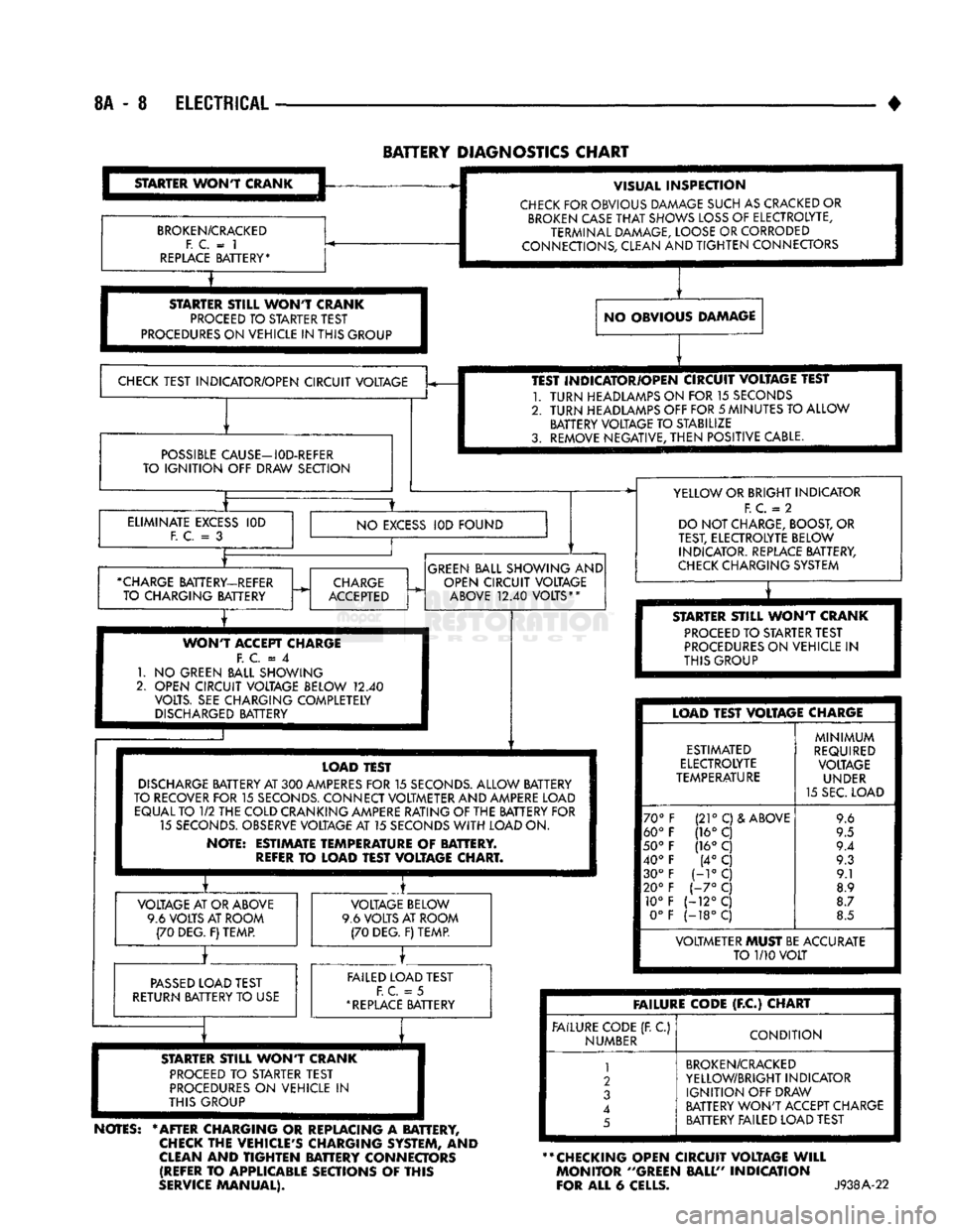
BATTERY
DIAGNOSTICS
CHART
STARTER
WONT
CRANK
BROKEN/CRACKED
F. C.
= 1
REPLACE
BATTERY* VISUAL
INSPECTION
CHECK
FOR OBVIOUS DAMAGE SUCH AS CRACKED OR
BROKEN
CASE
THAT
SHOWS
LOSS
OF ELECTROLYTE,
TERMINAL DAMAGE, LOOSE OR CORRODED
CONNECTIONS, CLEAN AND
TIGHTEN
CONNECTORS
STARTER
STILL
WONT
CRANK
PROCEED
TO STARTER TEST
PROCEDURES
ON VEHICLE IN THIS GROUP NO OBVIOUS DAMAGE
CHECK
TEST INDICATOR/OPEN CIRCUIT VOLTAGE
POSSIBLE
CAUSE—I0D-REFER
TO
IGNITION
OFF DRAW SECTION TEST INDICATOR/OPEN CIRCUIT VOLTAGE TEST
1.
TURN
HEADLAMPS ON FOR 15 SECONDS
2.
TURN
HEADLAMPS OFF FOR
5
MINUTES TO ALLOW BATTERY VOLTAGE TO STABILIZE
3. REMOVE NEGATIVE,
THEN
POSITIVE CABLE.
ELIMINATE
EXCESS
F. C.
= 3
IOD
NO
EXCESS
IOD FOUND
•CHARGE
BATTERY-REFER TO CHARGING BATTERY
CHARGE
ACCEPTED
GREEN
BALL SHOWING AND
OPEN CIRCUIT VOLTAGE
ABOVE
12.40
VOLTS**
WONT
ACCEPT CHARGE F.
C = 4
1.
NO
GREEN BALL SHOWING
2. OPEN CIRCUIT VOLTAGE BELOW
12.40
VOLTS. SEE CHARGING COMPLETELY
DISCHARGED
BATTERY YELLOW OR BRIGHT INDICATOR
F.
C.
= 2
DO NOT CHARGE, BOOST, OR
TEST, ELECTROLYTE BELOW INDICATOR. REPLACE BATTERY,
CHECK
CHARGING SYSTEM
T
STARTER
STILL
WONT
CRANK
PROCEED
TO STARTER TEST
PROCEDURES
ON VEHICLE
IN
THIS GROUP LOAD TEST
DISCHARGE
BATTERY AT
300
AMPERES
FOR
15
SECONDS.
ALLOW BATTERY
TO RECOVER FOR
15
SECONDS.
CONNECT VOLTMETER AND AMPERE LOAD EQUAL TO
1/2
THE COLD CRANKING AMPERE RATING OF THE BATTERY FOR 15
SECONDS.
OBSERVE VOLTAGE AT 15 SECONDS
WITH
LOAD ON.
NOTE: ESTIMATE TEMPERATURE
OF
BATTERY.
REFER
TO
LOAD TEST VOLTAGE CHART. VOLTAGE AT OR ABOVE
9.6 VOLTS AT ROOM (70 DEG. F) TEMP. VOLTAGE BELOW
9.6 VOLTS AT ROOM (70 DEG. F) TEMP.
PASSED
LOAD TEST
RETURN BATTERY TO USE FAILED LOAD TEST
F. C.
= 5
*
REPLACE
BATTERY LOAD TEST VOLTAGE CHARGE
ESTIMATED
ELECTROLYTE
TEMPERATURE
70°
60°
50°
40° 30°
20° 10° 0° (21°
C)& ABOVE
(16° C
(16°
C (4°
C
H°C
1-7°
C
(-12°C
(-18°C
MINIMUM
REQUIRED VOLTAGE UNDER
15 SEC. LOAD 9.6
9.5
9.4 9.3 9.1
8.9
8.7
8.5 VOLTMETER MUST BE ACCURATE
TO
1/10
VOLT
STARTER
ST8LL
WONT
CRANK
PROCEED
TO
STARTER TEST
PROCEDURES
ON
VEHICLE
IN
THIS GROUP
NOTES:
* AFTER CHARGING
OR
REPLACING
A
BATTERY,
CHECK
THE VEHICLE'S CHARGING SYSTEM,
AND
CLEAN
AND
TIGHTEN
BATTERY CONNECTORS (REFER
TO
APPLICABLE SECTIONS
OF
THIS
SERVICE
MANUAL). FAILURE CODE
(F.C)
CHART
FAILURE CODE (R
C)
NUMBER
CONDITION
1
2
3
4
5
BROKEN/CRACKED
YELLOW/BRIGHT INDICATOR
IGNITION
OFF DRAW
BATTERY
WON'T
ACCEPT CHARGE BATTERY FAILED LOAD TEST
** CHECKING OPEN CIRCUIT VOLTAGE
WILL
MONITOR ''GREEN BALL" INDICATION
FOR ALL
6
CELLS.
J938A-22
Page 331 of 1502
8A
- 10
ELECTRICAL
•
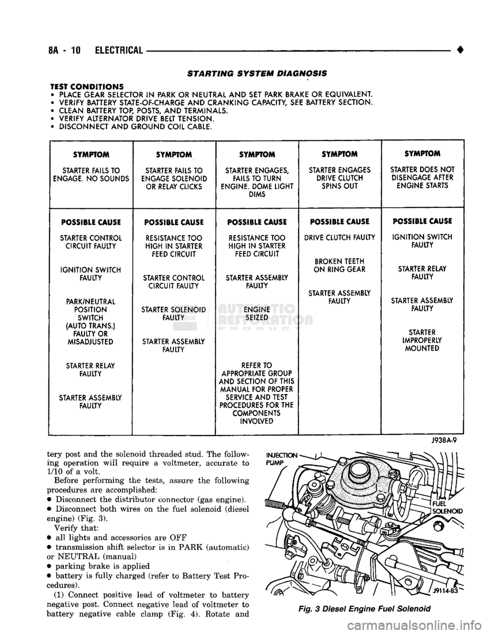
STARTING SYSTEM DIAGNOSIS
TEST CONDITIONS • PLACE GEAR SELECTOR
IN
PARK OR NEUTRAL AND SET PARK BRAKE
OR
EQUIVALENT. • VERIFY BATTERY STATE-OF-CHARGE AND CRANKING CAPACITY, SEE BATTERY SECTION.
• CLEAN BATTERY TOP, POSTS, AND TERMINALS.
• VERIFY ALTERNATOR DRIVE BELT TENSION.
• DISCONNECT AND GROUND COIL CABLE. SYMPTOM
SYMPTOM SYMPTOM SYMPTOM SYMPTOM
STARTER FAILS TO STARTER FAILS TO STARTER ENGAGES, STARTER ENGAGES STARTER DOES NOT
ENGAGE.
NO SOUNDS
ENGAGE
SOLENOID FAILS TO TURN DRIVE CLUTCH
DISENGAGE
AFTER
OR RELAY CLICKS ENGINE. DOME
LIGHT
SPINS
OUT
ENGINE STARTS
DIMS
POSSIBLE
CAUSE
POSSIBLE
CAUSE
POSSIBLE
CAUSE
POSSIBLE
CAUSE
POSSIBLE
CAUSE
STARTER CONTROL
RESISTANCE
TOO
RESISTANCE
TOO DRIVE CLUTCH
FAULTY
IGNITION
SWITCH
CIRCUIT
FAULTY
HIGH
IN
STARTER
HIGH
IN
STARTER
FAULTY
FEED CIRCUIT FEED CIRCUIT
BROKEN
TEETH
IGNITION
SWITCH ON RING GEAR
STARTER RELAY
FAULTY
STARTER CONTROL STARTER ASSEMBLY
FAULTY
CIRCUIT
FAULTY FAULTY
STARTER ASSEMBLY
PARK/NEUTRAL
FAULTY
STARTER ASSEMBLY
POSITION STARTER SOLENOID ENGINE
FAULTY
SWITCH
FAULTY
SEIZED
(AUTO
TRANS.) STARTER
FAULTY
OR STARTER
MISADJUSTED STARTER ASSEMBLY IMPROPERLY
FAULTY
MOUNTED
STARTER RELAY
REFER
TO
FAULTY
APPROPRIATE GROUP
AND SECTION OF THIS
MANUAL FOR PROPER
STARTER ASSEMBLY
SERVICE
AND TEST
FAULTY
PROCEDURES
FOR THE
COMPONENTS INVOLVED
J938A-9
tery post and the solenoid threaded stud. The follow
ing operation will require a voltmeter, accurate to 1/10 of a volt.
Before performing the tests, assure the following
procedures are accomplished:
•
Disconnect the distributor connector (gas engine).
•
Disconnect both wires on the fuel solenoid (diesel engine) (Fig. 3). Verify that:
•
all lights and accessories are OFF
•
transmission shift selector is in PARK (automatic)
or NEUTRAL (manual)
•
parking brake is applied
•
battery is fully charged (refer to Battery Test Pro
cedures). (1) Connect positive lead of voltmeter to battery
negative post. Connect negative lead of voltmeter to
battery negative cable clamp (Fig. 4). Rotate and
Fig.
3
Diesel
Engine
Fuel
Solenoid
Page 333 of 1502
8A
- 12
ELECTRICAL
•
ENGINE
STARTER
RELAY
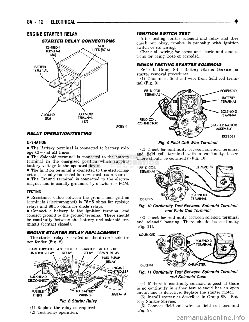
STARTER RELAY CONNECTIONS
GROUND SOLENOID (85) TERMINAL
(87) J928B-1
RELAY OPERATION/TESTING
OPERATION
• The Battery terminal is connected to battery volt
age (B +
)
at all times.
• The Solenoid terminal is connected to the battery
terminal in the energized position which supplies
battery voltage to the operated device. • The Ignition terminal is connected to the electromag
net and usually connected to a switched power source.
• The Ground terminal is connected to the electro
magnet and is usually grounded by a switch or PCM.
TESTING
• Resistance value between the ground and ignition
terminals (electromagnet) is
75
±5 ohms for resistor
relays and 86±5 ohms for diode relays.
• Connect a battery to the ignition terminal and
connect ground to the ground terminal. There should
be continuity between the battery and solenoid ter minals (contact closed).
ENGINE STARTER RELAY REPLACEMENT The starter relay is located on the driver's side in
ner fender (Fig. 8).
PART THROTTLE
A/C
CLUTCH STARTER AUTO SHUT
UNLOCK RELAY RELAY RELAY DOWN RELAY
Fig.
8
Starter
Relay
(1) Replace the relay as required.
(2) Test relay operation. IGNITION SWITCH TEST
After testing starter solenoid and relay and they
check out okay, trouble is probably with ignition
switch or its wiring. Check all wiring for opens and shorts and connec
tions for being loose or corroded.
BENCH TESTING STARTER SOLENOID Refer to Group 8B - Battery Starter Service for
starter removal procedures. (1) Disconnect field coil wire from field coil termi
nal (Fig. 9).
Fig.
9 Field
Coil
Wire
Terminal
(2) Check for continuity between solenoid terminal
and field coil terminal with a continuity tester.
There should be continuity (Fig. 10).
Fig.
10 Continuity Test Between
Solenoid
Terminal
and
Field
Coil
Terminal
(3) Check for continuity between solenoid terminal
and solenoid housing. There should be continuity
(Fig. 11).
SOLENOID
RR8BD33 Fig.
11 Continuity Test Between
Solenoid
Terminal
and Solenoid Case
(4) If there is continuity solenoid is good. If there
is no continuity in either test solenoid has an open
circuit and is defective. Replace the starter motor. (5) Install starter as described in Group 8B - Bat
tery Starter Service. (6) Connect field coil wire to field coil terminal
(Fig. 9).
Page 336 of 1502
•
ELECTRICAL
8A - 15 a
CASE
GROUND
CAPACITOR
ALTERNATOR ~L FIELD
TERMINALS
A
142-DG/OR BATTERY
VOLTAGE K20-DG
—!
GROUND
CASE
GROUND
til
ALTERNATOR BATTERY
TERMINAL ENGINE
CONTROLLER TO ENGINE
CONTROLLER TERMINAL
51
LESS
THAN
BATTERY VOLTAGE A21
DB-
.....
IGNITION SWITCH
20 AMP FUSE
AUTO
AH ^
SHUTDOWN POWER
RELAY
DISTRIBUTION
\
CENTER TEST
AMMETER JUMPER WIRE
TO GROUND
TEST
VOLTMETER
GO
5—n
DISCONNECTED
ALTERNATOR OUTPUT WIRE GROUND
ACC
Bl
OFF
RUN OFF
START*T
|ACC
CARBON
PILE RHEOSTAT
J938A-18
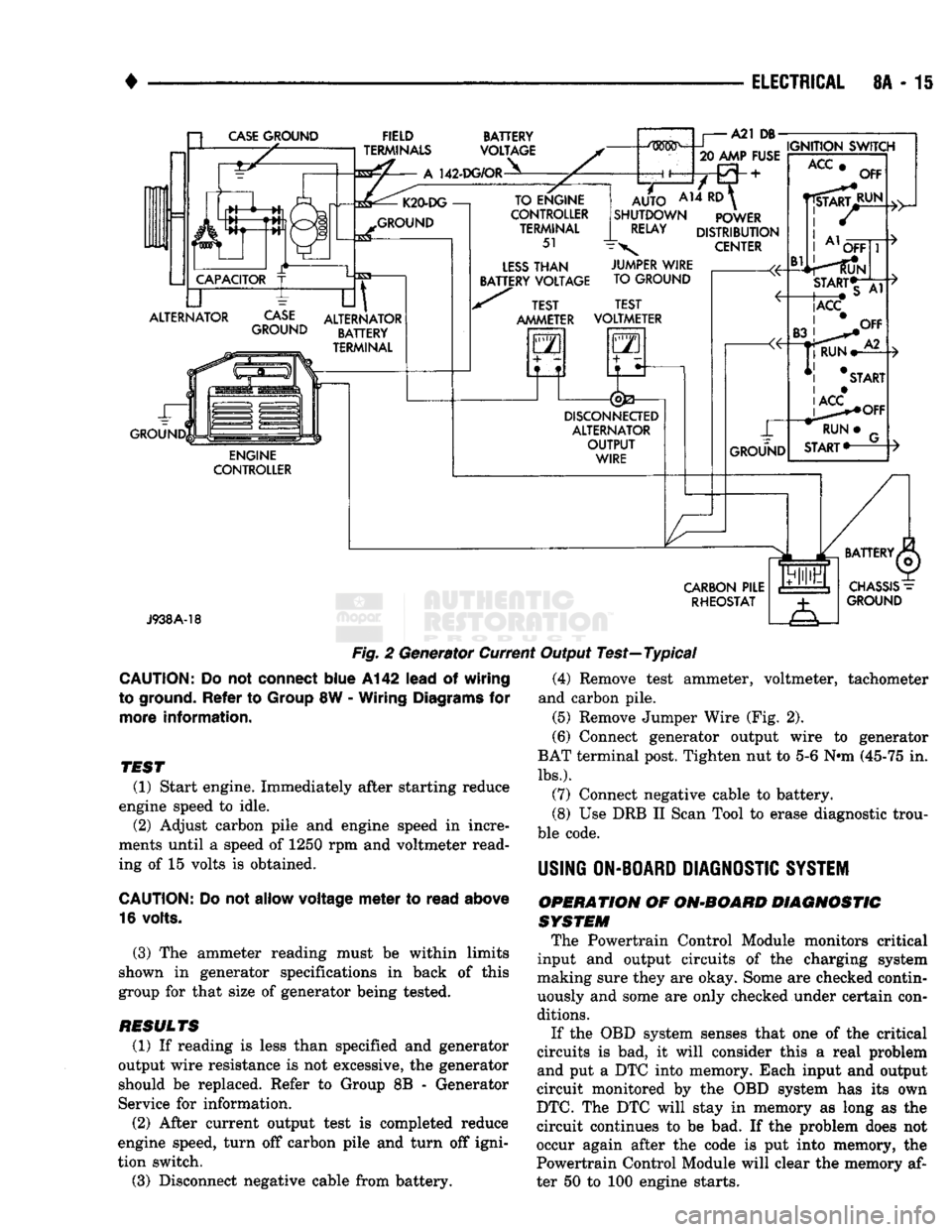
Fig.
2 Generator Current Output Test—Typical
CAUTION:
Do not
connect
blue
A142
lead
of
wiring
to ground.
Refer
to
Group
8W -
Wiring
Diagrams
for
more
information.
TEST
(1) Start engine. Immediately after starting reduce
engine speed to idle. (2) Adjust carbon pile and engine speed in incre
ments until a speed of 1250 rpm and voltmeter read
ing of 15 volts is obtained.
CAUTION:
Do not
allow
voltage
meter
to
read
above
16 volts.
(3) The ammeter reading must be within limits
shown in generator specifications in back of this
group for that size of generator being tested.
RESULTS
(1) If reading is less than specified and generator
output wire resistance is not excessive, the generator
should be replaced. Refer to Group 8B - Generator
Service for information.
(2) After current output test is completed reduce
engine speed, turn off carbon pile and turn off igni
tion switch.
(3) Disconnect negative cable from battery. (4) Remove test ammeter, voltmeter, tachometer
and carbon pile. (5) Remove Jumper Wire (Fig. 2).
(6) Connect generator output wire to generator
BAT terminal post. Tighten nut to 5-6 Nnn (45-75 in.
lbs.).
(7) Connect negative cable to battery.
(8) Use DRB II Scan Tool to erase diagnostic trou
ble code.
USING
ON-BOARD
DIAGNOSTIC
SYSTEM
OPERATION
OF
ON-BOARD
DIAGNOSTIC
SYSTEM
The Powertrain Control Module monitors critical
input and output circuits of the charging system
making sure they are okay. Some are checked contin
uously and some are only checked under certain con
ditions.
If the OBD system senses that one of the critical
circuits is bad, it will consider this a real problem
and put a DTC into memory. Each input and output
circuit monitored by the OBD system has its own
DTC.
The DTC will stay in memory as long as the
circuit continues to be bad. If the problem does not
occur again after the code is put into memory, the
Powertrain Control Module will clear the memory af
ter 50 to 100 engine starts.
Page 342 of 1502
• BATTERY/STARTER/GENERATOR
SERVICE
8B - 1
CONTENTS
page page
BATTERY
SERVICE
PROCEDURES
1 SPECIFICATIONS 9
GENERATOR
SERVICE
6 STARTER
SERVICE
PROCEDURES
4
BATTERY SERVICE PROCEDURES
GENERAL
INFORMATION This section will cover the Battery service, re
moval, and installation procedures only. For diagnos
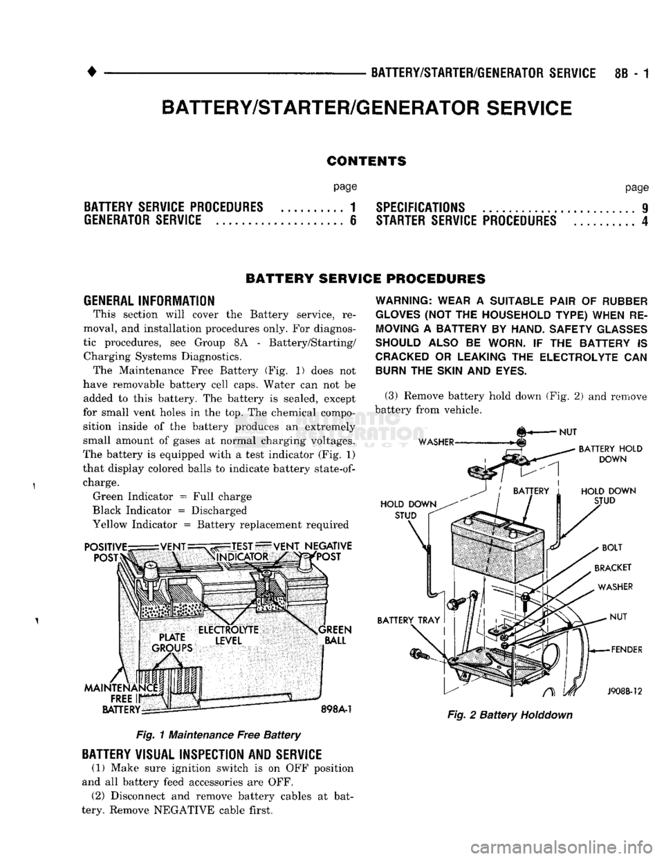
tic procedures, see Group 8A - Battery/Starting/ Charging Systems Diagnostics. The Maintenance Free Battery (Fig. 1) does not
have removable battery cell caps. Water can not be added to this battery. The battery is sealed, except
for small vent holes in the top. The chemical compo sition inside of the battery produces an extremely
small amount of gases at normal charging voltages.
The battery is equipped with a test indicator (Fig. 1)
that display colored balls to indicate battery
state-of-
charge. Green Indicator = Full charge
Black Indicator = Discharged
Yellow Indicator = Battery replacement required Fig. 1 Maintenance Free Battery
BATTERY
VISUAL INSPECTION AND
SERVICE
(1) Make sure ignition switch is on OFF position
and all battery feed accessories are OFF. (2) Disconnect and remove battery cables at bat
tery. Remove NEGATIVE cable first.
WARNING: WEAR
A
SUITABLE PAIR
OF
RUBBER
GLOVES
(NOT THE
HOUSEHOLD TYPE) WHEN
RE
MOVING
A
BATTERY
BY
HAND. SAFETY
GLASSES
SHOULD ALSO
BE
WORN.
IF THE
BATTERY
IS
CRACKED
OR
LEAKING
THE
ELECTROLYTE
CAN
BURN
THE
SKIN
AND
EYES.
(3) Remove battery hold down (Fig. 2) and remove
battery from vehicle. Fig. 2 Battery
Holddown
BATTERY/STARTER/GENERATOR
SERVICE
Page 343 of 1502
8B
- 2
BATTERY/STARTER/GENERATOR SERVICE
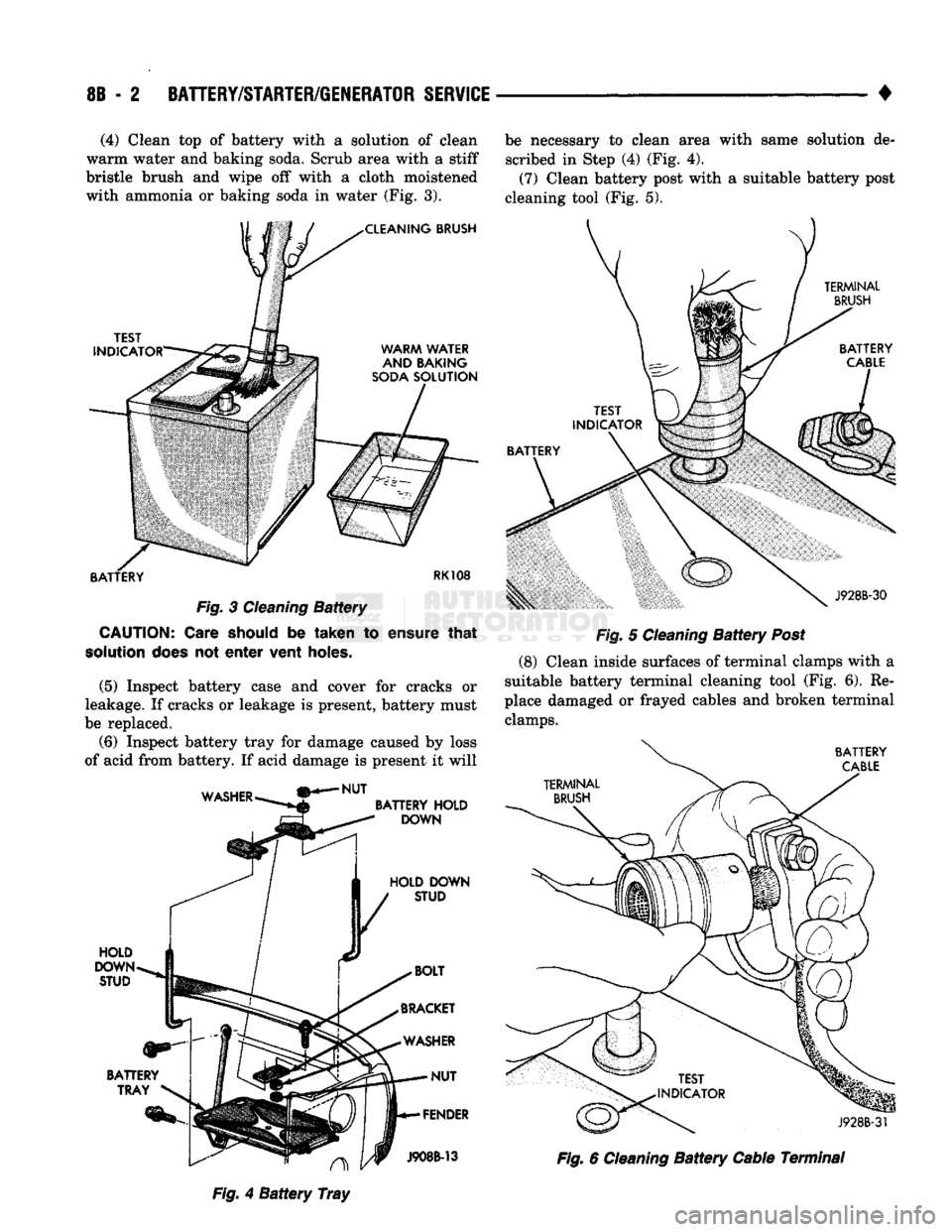
• (4) Clean top of battery with a solution of clean
warm water and baking soda. Scrub area with a stiff
bristle brush and wipe off with a cloth moistened
with ammonia or baking soda in water (Fig. 3). be necessary to clean area with same solution de
scribed in Step (4) (Fig. 4).
(7) Clean battery post with a suitable battery post
cleaning tool (Fig. 5).
TERMINAL
BRUSH
TEST
INDICATOR
BATTERY Fig.
3
Cleaning
Battery
CAUTION:
Care should
be
taken
to
ensure
that
solution
does
not
enter
vent holes.
(5) Inspect battery case and cover for cracks or
leakage. If cracks or leakage is present, battery must
be replaced.
(6) Inspect battery tray for damage caused by loss
of acid from battery. If acid damage is present it will J928B-30
Fig.
5
Cleaning
Battery
Post
(8)
Clean inside surfaces of terminal clamps with a
suitable battery terminal cleaning tool (Fig. 6). Re
place damaged or frayed cables and broken terminal clamps.
BATTERY
CABLE
WASHER
NUT
BATTERY
HOLD
DOWN
HOLD DOWN STUD HOLD
DOWN
STUD
BATTERY TRAY
J928B-3f A
Fig.
4
Battery
Tray
J908B-13
Fig.
6
Cleaning
Battery
Cable Terminal
Page 344 of 1502
•
BATTERY/STARTER/GENERATOR
SERVICE
8B - 3
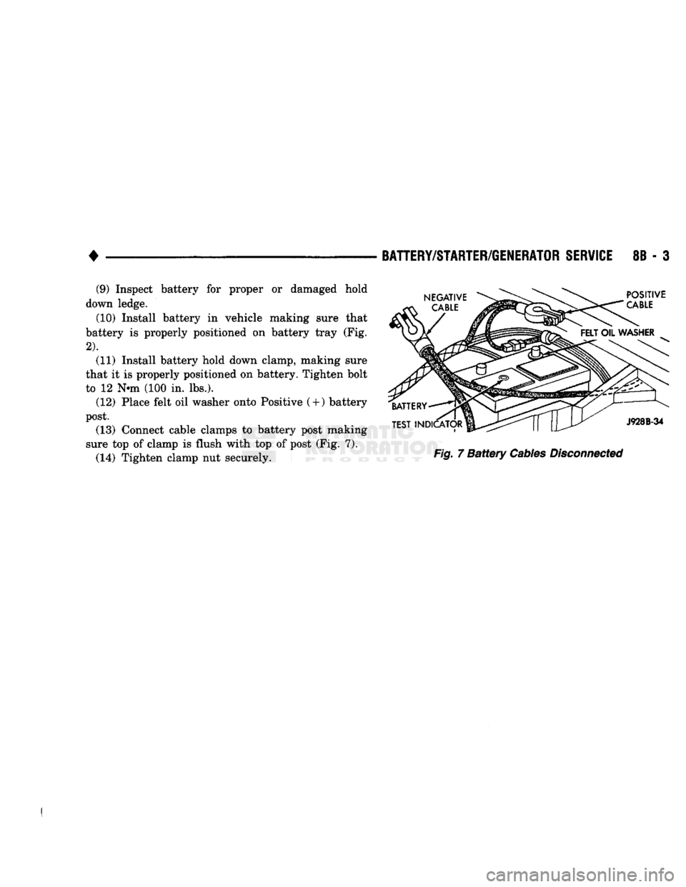
Fig.
7
Battery
Cables
Disconnected
(9) Inspect battery for proper or damaged hold
down ledge.
(10) Install battery in vehicle making sure that
battery is properly positioned on battery tray (Fig.
2).
(11) Install battery hold down clamp, making sure
that it is properly positioned on battery. Tighten bolt
to 12 N-m (100 in. lbs.). (12) Place felt oil washer onto Positive
(
+
)
battery
post. (13) Connect cable clamps to battery post making
sure top of clamp is flush with top of post (Fig. 7). (14) Tighten clamp nut securely.