service DODGE TRUCK 1993 Service Manual Online
[x] Cancel search | Manufacturer: DODGE, Model Year: 1993, Model line: TRUCK, Model: DODGE TRUCK 1993Pages: 1502, PDF Size: 80.97 MB
Page 272 of 1502
COOLING SYSTEM
CONTENTS page
DIAGNOSIS
... 4
ENGINE
ACCESSORY
DRIVE BELTS
40
ENGINE
BLOCK HEATERS
48
GENERAL
INFORMATION
Throughout this group, references are made to partic
ular vehicle models by alphabetical designation or by
the particular vehicle nameplate. A chart showing a
breakdown of alphabetical designations is included in
the Introduction section at the beginning of this man
ual.
5.9L gas powered engines will be' referred to as ei
ther: LDC (Light Duty Cycle) or HDC (Heavy Duty
Cycle).
COOLING
SYSTEM
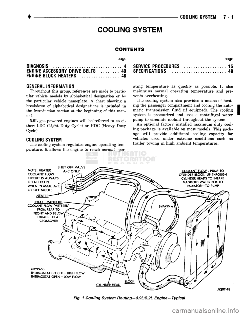
The cooling system regulates engine operating tem
perature. It allows the engine to reach normal oper-
page
SERVICE
PROCEDURES
15
SPECIFICATIONS
; 49
ating temperature as quickly as possible. It also
maintains normal operating temperature and pre
vents overheating.
The cooling system also provides a means of heat
ing the passenger compartment and cooling the auto
matic transmission fluid (if equipped). The cooling system is pressurized and uses a centrifugal water
pump to circulate coolant throughout the system.
An optional factory installed maximum duty cool
ing package is available on most models. This pack age will provide additional cooling capacity for
vehicles used under extreme conditions such as
trailer towing in high ambient temperatures.
NOTE: HEATER
COOLANT FLOW
CIRCUIT
IS
ALWAYS
OPEN
EXCEPT
WHEN
IN MAX. A/C
OR
OFF
MODES
HEATER
INTAKE MANIFOLD
COOLANT FLOW "METERED" FROM REAR
TO
FRONT
AND
BELOW EXHAUST
HEAT
CROSSOVER
SHUT
OFF
VALVE
A/C
ONLY COOLANT FLOW
-
PUMP
TO
CYLINDER BLOCK,
UP
THROUGH CYLINDER HEADS
TO
INTAKE MANIFOLD WATER
BOX TO
RADIATOR-TO PUMP
•BYPASS
THERMOSTAT CLOSED-HIGH FLOW
THERMOSTAT OPEN
- LOW
FLOW
J9207-18
Fig.
1
Cooling
System
Routing—3.9U5.2L Engine—Typical
Page 275 of 1502
DIAGNOSIS
PRELIMINARY
CHECKS
ENGINE COOLING SYSTEM OVERHEATING Establish what driving conditions caused the com
plaint. Abnormal loads on the cooling system such as
the following may be the cause:
1.
PROLONGED IDLE, VERY HIGH AMBI
ENT TEMPERATURE, SLIGHT TAIL WIND AT
IDLE, SLOW TRAFFIC, TRAFFIC JAMS, HIGH SPEED OR STEEP GRADES.
Driving techniques that avoid overheating are:
• Idle with A/C off when temperature gauge is at
end of normal range. * Increasing engine speed for more air flow is recom
mended.
2.
TRAILER TOWING: Consult Trailer Towing section of owners manual.
Do not exceed limits.
3.
AIR CONDITIONING; ADD-ON OR AFTER
MARKET: A maximum cooling package should have been or
dered with vehicle if add-on or after market A/C is
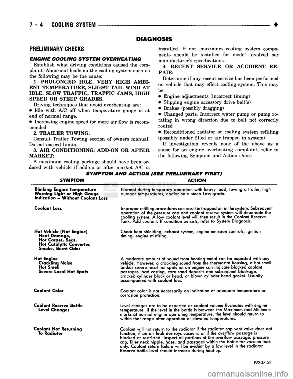
SYMPTOM AND ACTION
SYMPTOM
installed. If not, maximum cooling system compo
nents should be installed for model involved per
manufacturer's specifications.
4.
RECENT SERVICE OR ACCIDENT RE
PAIR:
Determine if any recent service has been performed
on vehicle that may effect cooling system. This may
be:
• Engine adjustments (incorrect timing)
• Slipping engine accessory drive belt(s) • Brakes (possibly dragging)
• Changed parts. Incorrect water pump or pump ro
tating in wrong direction due to belt not correctly
routed
• Reconditioned radiator or cooling system refilling (possibly under filled or air trapped in system).
If investigation reveals none of the above as a
cause for an engine overheating complaint, refer to
the following Symptom and Action chart:
PRELIMINARY FIRST) ACTION
Blinking Engine Temperature
Warning Light or High Gauge indication - Without Coolant Loss
Normal during temporary operation
with
heavy load, towing
a
trailer,
high
outdoor temperatures, and/or on
a
steep
Loss
grade.
Coolant Loss
Hot Vehicle (Not Engine) Heat Damage,
Hot Carpet, Seat,
Hot
Catalytic
Converter,
Smoke, Burnt Odor
Hot Engine Crackling Noise Hot Smell
Severe Local Hot Spots
Coolant Color
Coolant Reserve Bottle Level Changes
Coolant Not Returning To Radiator
Improper refilling procedures
can
result
in
trapped air
in
the
system.
Subsequent
operation
of the
pressure cap and coolant reserve system
will
deaereate
the
cooling
system.
A low
coolant
level
will
then result
in the
Coolant Reserve
Tank. Add coolant.
If
condition persists,
refer
to
System
Diagnosis.
Check
heat shielding, exhaust
system,
engine emission controls, ignition
timing, engine misfiring.
A
moderate amount
of
sound from heating
metal
can
be
expected
with
any
vehicle. However,
a
crackling sound from
trie
thermostat
housing,
a hot
smell and/or severe local
hot
spots on
an
engine can indicate blocked coolant
passages,
bad castina, core sand deposits and subsequent blockage,
cracked cylinder block
or
head,
or
blown cylinder head gasket. Usually
accompanied
with
coolant
loss.
Coolant
color is
not
necessarily
an
indication
of
adequate
temperature
or
corrosion
protection.
Level changes
are to be
expected as coolant volume fluctuates
with
engine
temperature.
If the
level
in the
bottle
is
between
the
Maximum and Minimum
marks
at
normal engine operating temperature,
the
level
should
return
to
within
that
range
after
operation
at
elevated temperatures.
Coolant
will
not
return
to the
radiator
if the
radiator cap vent valve does
not
function,
if
an
air
leak destroys vacuum,
or if the
overflow
passage
is
blocked
or
restricted. Inspect
all
portions
of the
overflow
passage,
pressure
cap,
filler
neck nipple, hose, and
passages
within
the
bottle
for
vacuum leak
only. Coolant
return
failure
will
be
evident
by a low
level
in the
radiator.
Reserve
bottle
level
should increase during heat-up.
J9207-31
Page 286 of 1502
•
COOLING SYSTEM
7 - 15
SERVICE
PROCEDURES
INDEX
page
Coolant
26
Coolant Reserve/Overflow System
30
Cooling System Cleaning/Reverse Flushing
28
Cooling System Fan—Diesel Engine
. 37
Cooling System
Fan—Gas
Engines
36
Cooling System
Hoses
34
Draining Cooling System
27
Pressure
Testing
Radiator
Caps
............. 32
Radiator Pressure
Cap 31
Radiators
32
Refilling
the
Cooling System
28
WATER PUMPS—EXCEPT DIESEL
A centrifugal water pump circulates coolant
through the water jackets, passages, intake manifold,
radiator core, cooling system hoses and heater core.
The pump is driven from the engine crankshaft by a drive belt. The water pump impeller is pressed onto the rear
of a shaft that rotates in a bearing pressed into the
water pump body. The body has a small hole for ven
tilation. The water pump seals are lubricated by an
tifreeze in the coolant mixture. Additional lubrication is not necessary. A quick test to determine if pump is working is to
check if heater warms properly. A defective water
pump will not be able to circulate heated coolant
through the long heater hose to the heater core. The water pump on all models can be removed
without discharging the air conditioning system (if equipped).
REMOVAL The water pump on all gas powered engines is
bolted directly to the engine timing chain case/cover.
A gasket is used as a seal between the water pump
and timing chain case/cover.
If water pump is replaced because of bearing/shaft
damage or leaking shaft seal, the mechanical cooling
fan assembly should also be inspected. Inspect for fa tigue cracks, loose blades or loose rivets that could
have resulted from excessive vibration. Replace fan if any of these conditions are found. Also check condi
tion of the thermal viscous fan drive. Refer to Vis
cous Fan Drive in this group. (1) Disconnect negative battery cable from battery.
(2) Drain cooling system. Refer to Draining Cool
ing System in this group. Do not waste reusable coolant. If solution is clean,
drain coolant into a clean container for reuse.
(3)
Disconnect throttle cable from clip at top of fan
shroud.
page
Testing
Cooling System
for
Leaks
. 29
Thermostat
22
Transmission
Oil
Cooler—Diesel
35
Transmission
Oil
Cooler—Except Diesel
35
Transmission Oil-To-Air Cooler
36
Viscous
Fan
Drive
38
Water
Pump
Bypass
Hose—All
Gas
Powered
Engines
.............................. 19
Water
Pumps—5.9L Diesel
18
Water
Pumps—Except Diesel
15
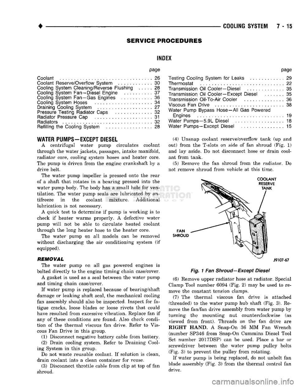
(4) Unsnap coolant reserve/overflow tank (up and
out) from the T-slots on side of fan shroud (Fig. 1) and lay aside. Do not disconnect hose or drain cool
ant from tank.
(5) Remove the fan shroud from the radiator. Do
not remove shroud from vehicle at this time.
FAN
SHROUD
J9107-67
Fig.
1 Fan
Shroud—Except
Diesel
(6) Remove upper radiator hose at radiator. Special
Clamp Tool number 6094 (Fig. 2) may be used to re
move the constant tension clamps.
(7) The thermal viscous fan drive is attached
(threaded) to the water pump hub shaft (Fig. 3). Re
move the fan/fan drive assembly from water pump by
turning the mounting nut counterclockwise (as viewed from front). Threads on the fan drive are RIGHT HAND. A Snap-On 36 MM Fan Wrench (number SP346 from Snap-On Cummins Diesel Tool
Set number 2017DSP) can be used. Place a bar or
screwdriver between the water pump pulley bolts (Fig. 3) to prevent the pulley from rotating.
If water pump is being replaced, do not unbolt fan
blade assembly (Fig. 3) from the thermal control fan drive.
Page 298 of 1502
•
COOLING
SYSTEM
7 - 27 down to -67.7°C (-90°F). A higher percentage will
freeze at a warmer temperature. Also, a higher per centage of antifreeze can cause the engine to over
heat because specific heat of antifreeze is lower than
that of water.
CAUTION:
Richer
antifreeze
mixtures
cannot
be
measured
with
normal
field
equipment
and can
cause
problems
associated
with 100
percent
ethyl
ene-glycol.
COOLANT SELECTION-ADDITIVES The presence of aluminum components in the cool
ing system requires strict corrosion protection. Main
tain coolant at specified level with a mixture of ethylene-glycol based antifreeze and water. Only use an antifreeze containing ALUGARD 340-2
™
such as
Mopar Antifreeze. If coolant becomes contaminated
or looses color, drain and flush cooling system and
fill with correctly mixed solution.
A 0.25 percent emulsifiable oil is added to the ra
diator at the factory to prevent solder corrosion.
CAUTION:
Do not use
coolant
additives
that are
claimed
to
improve
engine
cooling.
COOLANT SERVICE-EXCEPT DIESEL It is recommended that the cooling system be
drained and flushed at 84,000 kilometers (52,500
miles) or 3 years, whichever occurs first. Then every
two years or 48,000 kilometers (30,000 miles), which ever occurs first.
COOLANT SERVICE-DIESEL ENGINE It is recommended that the cooling system be
drained and flushed every 24 months or 38,600 kilo meters (24,000 miles), whichever occurs first.
COOLANT LEVEL CHECK-ROUTINE Do not remove radiator cap for routine coolant
level inspections. The coolant level can be checked at the coolant reserve/overflow tank.
The coolant reserve/overflow system provides a
quick visual method for determining the coolant
level without removing the radiator pressure cap.
With engine idling and at normal operating temper ature, observe coolant level in coolant reserve/over
flow tank. The coolant level should be between the MIN and MAX (diesel engine) or ADD and FULL (gas engines) marks.
ADDING ADDITIONAL COOLANT-ROUTINE Do not remove the radiator cap to add coolant
to the system. When adding coolant to maintain the correct level, do so at the coolant reserve/overflow
tank with a 50/50 mixture of ethylene-glycol anti
freeze (containing Alugard 340-2 ™) and water. Re move the radiator cap only for testing or when
refilling the system after service. Removing cap un necessarily can cause loss of coolant and allow air to
enter system. This produces corrosion.
COOLANT LEVEL CHECK-SERVICE The cooling system is closed and designed to main
tain coolant level to the top of the radiator.
WARNING:
DO
NOT OPEN RADIATOR DRAINCOCK
WITH
ENGINE RUNNING
OR
WHILE ENGINE
IS HOT
AND COOLING
SYSTEM
IS
UNDER
PRESSURE.
When vehicle servicing requires a coolant level
check in the radiator, drain several ounces of coolant
from the radiator drain cock. Do this while observing
the coolant reserve/overflow system tank. The cool ant level in the reserve/overflow tank should drop
slightly. If not, inspect for a leak between radiator and coolant reserve/overflow system connection. Re
move radiator cap. The coolant level should be to the
top of the radiator. If not and if coolant level in re serve/overflow tank is at the ADD (gas engines) or
MIN (5.9L diesel engine) mark, check for:
• An air leak in the coolant reserve/overflow tank
• An air leak in the radiator filler neck
• Leak in the pressure cap seal to the radiator filler
neck
LOW COOLANT LEVEL-AERATION If the coolant level in the radiator drops below the
top of the radiator core tubes, air will enter the sys
tem. Low coolant level can cause the thermostat pellet
to be suspended in air instead of coolant. This will cause the thermostat to open later, which in turn causes higher coolant temperature. Air trapped in
cooling system also reduces the amount of coolant
circulating in the heater core. This may result in low
heat output.
DEAERATION As the engine operates, air trapped in the cooling
system gathers under the radiator cap. The next time
engine is operated, thermal expansion of coolant will
push trapped air past radiator cap into coolant re serve/overflow tank. Here it escapes to atmosphere in
the tank. When engine cools down the coolant, it will
be drawn from reserve/overflow tank into radiator to replace removed air.
DRAINING
COOLING
SYSTEM
WARNING:
DO NOT
REMOVE
THE
CYLINDER BLOCK DRAIN PLUGS
OR
LOOSEN THE RADIATOR
DRAIN PLUG
WITH
SYSTEM
HOT AND
UNDER
PRESSURE.
SERIOUS BURNS
FROM
COOLANT
CAN OCCUR.
Page 302 of 1502
•
COOLING
SYSTEM
7 - 31 It utilizes thermal expansion and contraction of cool
ant to keep coolant free of trapped air. It provides a
volume for expansion and contraction of coolant. It
also provides a convenient and safe method for
checking coolant level and adjusting level at atmo
spheric pressure. This is done without removing ra
diator pressure cap. It also provides some reserve
coolant to cover minor leaks and evaporation or boil
ing losses.
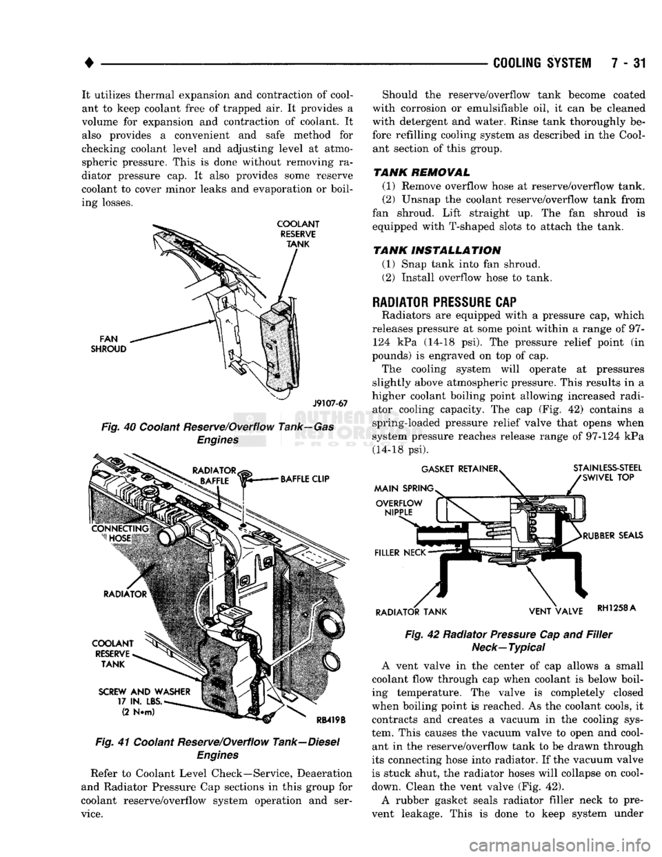
FAN
SHROUD
J9107-67
Fig.
40 Coolant Reserve/Overflow Tank—Gas
Engines
Fig.
41 Coolant Reserve/Overflow Tank—Diesel
Engines
Refer to Coolant Level Check—Service, Deaeration
and Radiator Pressure Cap sections in this group for
coolant reserve/overflow system operation and ser
vice.
Should the reserve/overflow tank become coated
with corrosion or emulsifiable oil, it can be cleaned
with detergent and water. Rinse tank thoroughly be
fore refilling cooling system as described in the Cool ant section of this group.
TANK REMOVAL
(1) Remove overflow hose at reserve/overflow tank.
(2) Unsnap the coolant reserve/overflow tank from
fan shroud. Lift straight up. The fan shroud is
equipped with T-shaped slots to attach the tank.
TANK INSTALLATION
(1) Snap tank into fan shroud.
(2) Install overflow hose to tank.
RADIATOR
PRESSURE
CAP
Radiators are equipped with a pressure cap, which
releases pressure at some point within a range of 97- 124 kPa (14-18 psi). The pressure relief point (in
pounds) is engraved on top of cap. The cooling system will operate at pressures
slightly above atmospheric pressure. This results in a
higher coolant boiling point allowing increased radi ator cooling capacity. The cap (Fig. 42) contains a
spring-loaded pressure relief valve that opens when
system pressure reaches release range of 97-124 kPa (14-18 psi).
Fig.
42 Radiator
Pressure
Cap and
Filler
Neck—Typical
A vent valve in the center of cap allows a small
coolant flow through cap when coolant is below boil
ing temperature. The valve is completely closed
when boiling point is reached. As the coolant cools, it contracts and creates a vacuum in the cooling sys
tem. This causes the vacuum valve to open and cool ant in the reserve/overflow tank to be drawn through
its connecting hose into radiator. If the vacuum valve
is stuck shut, the radiator hoses will collapse on cool-
down. Clean the vent valve (Fig. 42).
A rubber gasket seals radiator filler neck to pre
vent leakage. This is done to keep system under
Page 303 of 1502
7 - 32
COOLING
SYSTEM
• pressure. It also maintains vacuum during coolant
cool-down allowing coolant to return from reserve/
overflow tank.
RADIATOR
CAP-TO-FILLER
NECK
SEAL-PRESSURE RELIEF CHECK The pressure cap upper gasket (seal) pressure relief
can be tested by removing overflow hose from radia
tor filler neck nipple. Attach hose of pressure tester
tool 7700 or equivalent to nipple. It will be necessary
to disconnect hose from its adapter for filler neck.
Pump air into radiator. The pressure cap upper gas
ket should relieve at 69-124 kPa (10-18 psi) and hold
pressure at a minimum of 55 kPa (8 psi).
WARNING;
THE
WARNING WORDS
-DO NOT
OPEN HOT—
ON
RADIATOR PRESSURE CAP, ARE
A SAFETY PRECAUTION. WHEN
HOT,
PRESSURE BUILDS
UP IN
COOLING SYSTEM.
TO
PREVENT
SCALDING
OR
INJURY, RADIATOR
CAP
SHOULD NOT
BE
REMOVED WHILE SYSTEM
IS HOT
AND/OR UNDER
PRESSURE.
Do not remove radiator cap at any time except for
the following purposes: • Check and adjust antifreeze freeze point
• Refill system with new antifreeze
• Conducting service procedures
• Checking for vacuum leaks
WARNING;
IF
VEHICLE HAS BEEN RUN RECENTLY,
WAIT
AT
LEAST
15
MINUTES BEFORE REMOVING
RADIATOR CAP.
WITH
A
RAG, SQUEEZE RADIA
TOR UPPER HOSE
TO
CHECK
IF
SYSTEM
IS UN
DER
PRESSURE.
PLACE
A RAG
OVER
CAP AND
WITHOUT
PUSHING
CAP
DOWN, ROTATE
IT
COUNTER-CLOCKWISE
TO
FIRST STOP. ALLOW FLUID
TO
ESCAPE THROUGH
THE
COOLANT RE
SERVE/OVERFLOW HOSE
INTO
RESERVE/OVER FLOW TANK. SQUEEZE RADIATOR UPPER HOSE
TO DETERMINE WHEN PRESSURE HAS BEEN RE
LEASED.
WHEN COOLANT AND STEAM STOP BE
ING PUSHED
INTO
TANK AND SYSTEM PRESSURE
DROPS,
REMOVE RADIATOR CAP COMPLETELY.
PRESSURE
TESTING
RADIATOR
CAPS
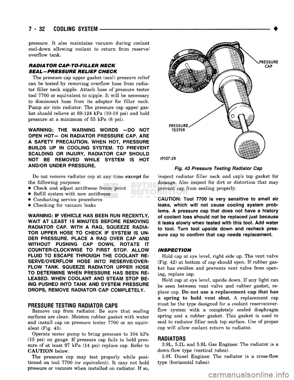
Remove cap from radiator. Be sure that sealing
surfaces are clean. Moisten rubber gasket with water
and install cap on pressure tester 7700 or an equiv
alent (Fig. 43). Operate tester pump to bring pressure to 104 kPa
(15 psi) on gauge. If pressure cap fails to hold pres
sure of at least 97 kPa (14 psi) replace cap. Refer to
CAUTION below. The pressure cap may test properly while posi
tioned on tool 7700 (or equivalent). It may not hold
pressure or vacuum when installed on radiator. If so,
Fig.
43
Pressure
Testing Radiator Cap
inspect radiator filler neck and cap's top gasket for
damage. Also inspect for dirt or distortion that may
prevent cap from sealing properly.
CAUTION:
Tool
7700
is
very
sensitive
to
small
air
leaks,
which
will
not
cause
cooling
system
prob
lems.
A
pressure
cap
that
does
not
have
a
history
of
coolant
loss
should
not be
replaced
just
because
it
leaks
slowly
when
tested
with
this
tool.
Add
water
to
tool.
Turn
tool
upside
down
and
recheck
pres
sure
cap to
confirm
that
cap
needs
replacement.
INSPECTION
Hold cap at eye level, right side up. The vent valve
(Fig. 42) at bottom of cap should open. If rubber gas
ket has swollen and prevents vent valve from open ing, replace cap.
Hold cap at eye level, upside down. If any light can
be seen between vent valve and rubber gasket, re place cap. Do not use a replacement cap that has a spring to hold vent shut. A replacement cap
must be the type designed for a coolant reserve/over
flow system with a completely sealed diaphragm spring and a rubber gasket. This gasket is used to
seal to radiator filler neck top surface. Use of proper
cap will allow coolant return to radiator.
RADIATORS
3.9L, 5.2L and 5.9L Gas Engines: The radiator is a
down-flow type (vertical tubes). 5.9L Diesel Engines: The radiator is a cross-flow
type (horizontal tubes).
Page 305 of 1502
7 - 34
COOLING SYSTEM
•
WARNING;
DO NOT
REMOVE
THE
CYLINDER
BLOCK DRAIN PLUGS
OR
LOOSEN
THE
RADIATOR
DRAINCOCK
WITH
THE
SYSTEM
HOT AND
UNDER
PRESSURE.
SERIOUS BURNS FROM COOLANT
CAN OCCUR.
(2) Drain the cooling system. Refer to Draining
Cooling System in this group. (3) Remove hose clamps and hoses from radiator.
Remove coolant reserve/overflow tank hose from ra diator filler neck nipple.
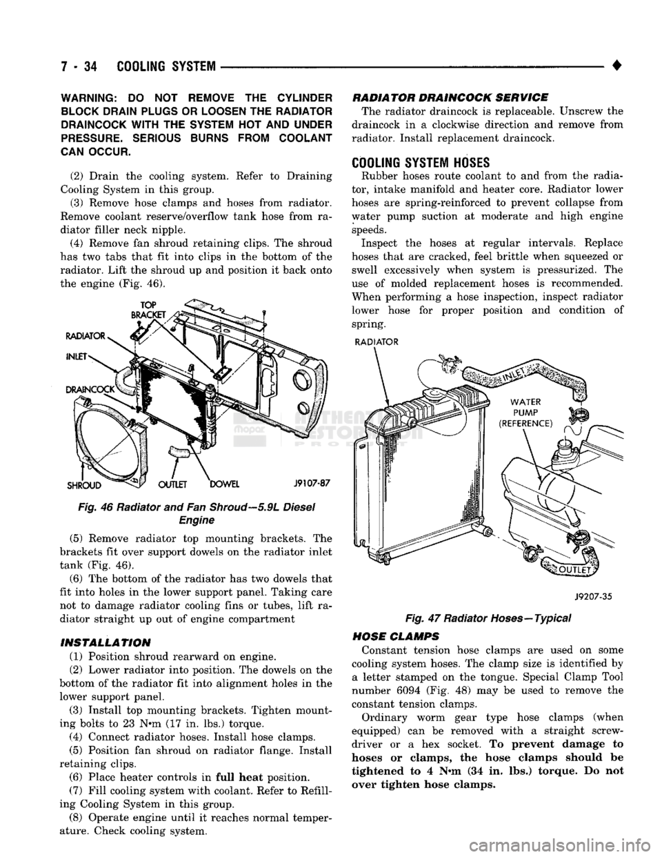
(4) Remove fan shroud retaining clips. The shroud
has two tabs that fit into clips in the bottom of the radiator. Lift the shroud up and position it back onto
the engine (Fig. 46).
Fig. 46 Radiator and Fan
Shroud—5.9L
Diesel Engine
(5) Remove radiator top mounting brackets. The
brackets fit over support dowels on the radiator inlet
tank (Fig. 46).
(6) The bottom of the radiator has two dowels that
fit into holes in the lower support panel. Taking care not to damage radiator cooling fins or tubes, lift ra
diator straight up out of engine compartment
INSTALLATION (1) Position shroud rearward on engine.
(2) Lower radiator into position. The dowels on the
bottom of the radiator fit into alignment holes in the lower support panel.
(3) Install top mounting brackets. Tighten mount
ing bolts to 23 N*m (17 in. lbs.) torque. (4) Connect radiator hoses. Install hose clamps.
(5) Position fan shroud on radiator flange. Install
retaining clips. (6) Place heater controls in full heat position.
(7) Fill cooling system with coolant. Refer to Refill
ing Cooling System in this group.
(8) Operate engine until it reaches normal temper
ature. Check cooling system. RADIATOR DRAINCOCK SERVICE
The radiator draincock is replaceable. Unscrew the
draincock in a clockwise direction and remove from
radiator. Install replacement draincock.
COOLING SYSTEM HOSES
Rubber hoses route coolant to and from the radia
tor, intake manifold and heater core. Radiator lower
hoses are spring-reinforced to prevent collapse from
water pump suction at moderate and high engine speeds. Inspect the hoses at regular intervals. Replace
hoses that are cracked, feel brittle when squeezed or swell excessively when system is pressurized. The
use of molded replacement hoses is recommended.
When performing a hose inspection, inspect radiator lower hose for proper position and condition of spring.
RADIATOR
J9207-35
Fig. 47 Radiator Hoses—Typical
HOSE CLAMPS Constant tension hose clamps are used on some
cooling system hoses. The clamp size is identified by a letter stamped on the tongue. Special Clamp Tool
number 6094 (Fig. 48) may be used to remove the
constant tension clamps.
Ordinary worm gear type hose clamps (when
equipped) can be removed with a straight screw
driver or a hex socket. To prevent damage to
hoses or clamps, the hose clamps should be
tightened to 4 N«m (34 in. lbs.) torque. Do not
over tighten hose clamps.
Page 317 of 1502

7
- 4S
COOLING
SYSTEM
•
PULLEY BOLT IDLER
iUlLTPULLEY-
TENSIONER
MOUNTING
BOLT TENSIONER
ASSEMBLY
TENSIONER \
rULLC,\
, / ^ J9307-64 ,
Fig.
11 Beit Tensioner—5.9L
HDC-Gas
Engine
MOUNT.
BOLT
3/8
SQUARE HOLE
ACCESSORY
DRIVE
BELT AUTOMATIC
BELT
TENSIONER
J9307-59
Fig.
12 Belt Tensioner—5.9L
Diesel
Engine—Typical
3MLm.2Lm.9L
LDG°GA8
ENGINES
REMOVAL
(1) Remove accessory drive belt. Refer to Belt Re
moval/Installation in this group. (2) Disconnect wiring and secondary cable from ig
nition coil.
(3) Remove ignition coil from coil mounting
bracket (two bolts). Do not remove coil mounting
bracket from cylinder head. (4) Remove tensioner assembly from mounting
bracket (one nut) (Fig. 13).
WARNING: BECAUSE
OF
HIGH
SPRING
PRES
SURE,
DO
NOT ATTEMPT
TO
DISASSEMBLE
AUTO
MATIC
TENSIONER.
UNIT
IS
SERVICED
AS AN
ASSEMBLY
(EXCEPT
FOR
PULLEY).
TENSIONER
MOUNTING NUT
INDEXING ARROW
INDEXING MARK
J9207-17
Fig.
13 indexing Marks-3.9L/5.2L/5.9L
LDC-Gas
Engine
(5) Remove pulley bolt. Remove pulley from ten
sioner.
INSTALLATION
(1) Install pulley and pulley bolt to tensioner.
Tighten bolt to 61 Nnn (45 ft. lbs.).
(2) Install tensioner assembly to mounting bracket.
An indexing tab is located on back of tensioner.
Align this tab to slot in mounting bracket. Tighten nut to 67 Nnn (50 ft. lbs.) torque.
(3) Connect all wiring to ignition coil. (4) Install coil to coil bracket. If nuts and bolts are
used to secure coil to coil bracket, tighten to 11 Nnn (100 in. lbs.) torque. If coil mounting bracket has
been tapped for coil mounting bolts, tighten bolts to 5 Nnn (50 in. lbs.) torque.
CAUTION:
To
prevent damage
to
coil case, coil mounting bolts must
be
torqued.
(5) Install drive belt. Refer to Belt Removal/Instal
lation in this group. (6) Check belt indexing marks (Fig. 13).
Page 318 of 1502
•
COOLING
SYSTEM
7 - 47 5.9L HDC'GAS ENGINE
REMOVAL
(1) Remove accessory drive belt. Refer to Belt Re
moval/Installation in this group. (2) Remove tensioner mounting bolt (Fig. 11) and
remove tensioner.
CAUTION:
If the
pulley
is to be
removed
from
the
tensioner,
its
mounting
bolt has
left
hand
threads.
WARNING:
BECAUSE
OF
HIGH SPRING
PRES
SURE,
DO
NOT ATTEMPT TO
DISASSEMBLE
AUTO MATIC TENSIONER. UNIT
IS
SERVICED
AS AN
ASSEMBLY
(EXCEPT FOR PULLEY).
INSTALLATION
(1) Install pulley and pulley bolt to tensioner (ob
serve the previous CAUTION). Tighten bolt to 88
N*m (65 ft. lbs.) torque.
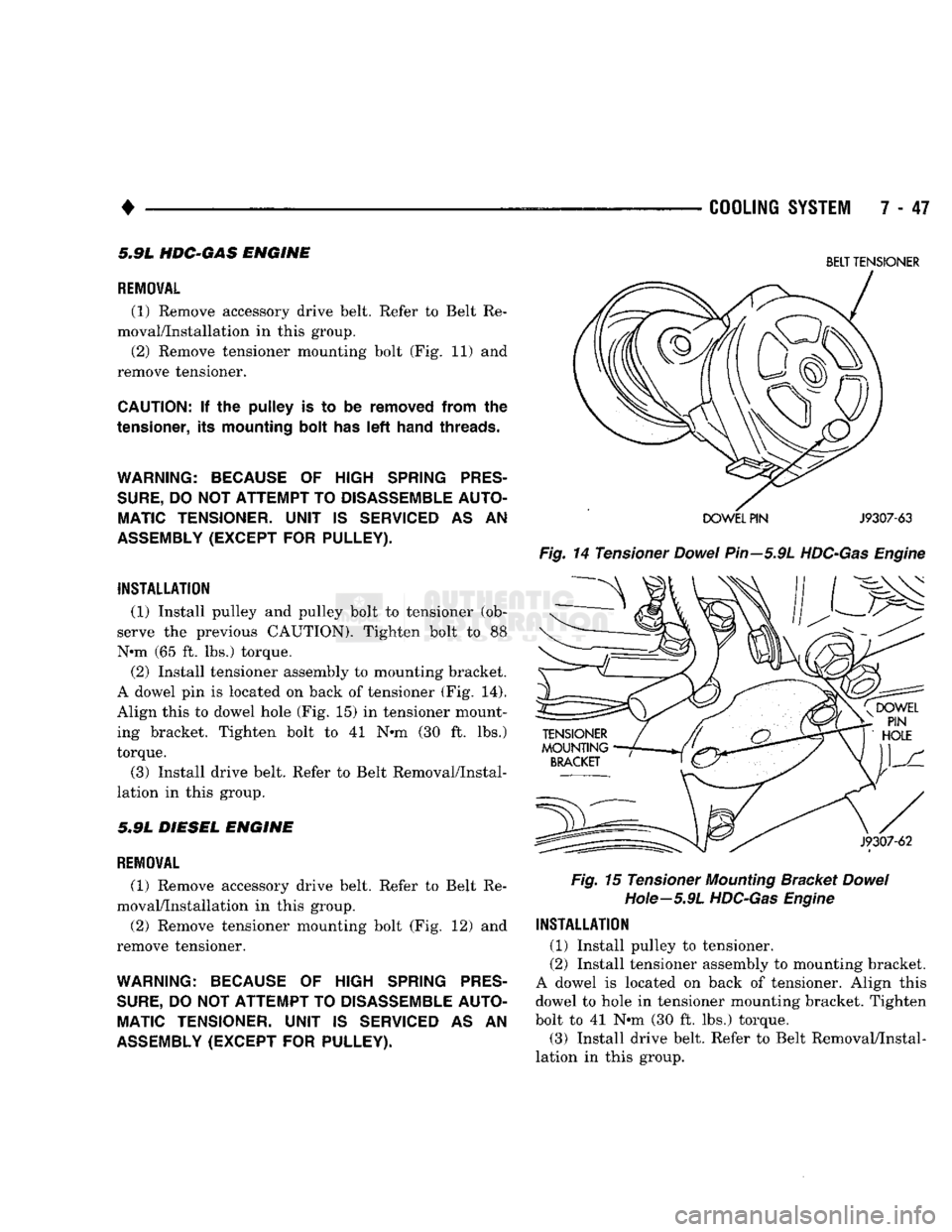
(2) Install tensioner assembly to mounting bracket.
A dowel pin is located on back of tensioner (Fig. 14).
Align this to dowel hole (Fig. 15) in tensioner mount
ing bracket. Tighten bolt to 41 N-m (30 ft. lbs.)
torque.
(3) Install drive belt. Refer to Belt Removal/Instal
lation in this group.
5.9L DIESEL ENGINE
REMOVAL
(1) Remove accessory drive belt. Refer to Belt Re
moval/Installation in this group. (2) Remove tensioner mounting bolt (Fig. 12) and
remove tensioner.
WARNING:
BECAUSE
OF
HIGH SPRING
PRES
SURE,
DO
NOT ATTEMPT
TO
DISASSEMBLE
AUTO MATIC TENSIONER. UNIT
IS
SERVICED
AS AN
ASSEMBLY
(EXCEPT FOR PULLEY).
BELT
TENSIONER
DOWEL
PIN
J9307-63
Fig.
14 Tensioner
Dowel
Pin—5.9L
HDC-Gas
Engine
Fig.
15 Tensioner
Mounting
Bracket
Dowel
Hole—5.9L
HDC-Gas
Engine
INSTALLATION
(1) Install pulley to tensioner.
(2) Install tensioner assembly to mounting bracket.
A dowel is located on back of tensioner. Align this
dowel to hole in tensioner mounting bracket. Tighten
bolt to 41 N*m (30 ft. lbs.) torque.
(3) Install drive belt. Refer to Belt Removal/Instal
lation in this group.
Page 322 of 1502
•
ELECTRICAL
ELECTRICAL
8A - 1
Group
AUDIO
SYSTEMS
8F
BATTERY/STARTER/GENERATOR
SERVICE
.. 8B
BATTERY/STARTING/CHARGING
SYSTEMS
DIAGNOSTICS
8A
HORNS
8G
IGNITION
SYSTEMS
8D
INSTRUMENT PANEL AND
GAUGES
8E
LAMPS
8L
POWER
LOCKS
8P
INDEX
Group
POWER
MIRRORS
8T
POWER
WINDOWS 8S
REAR
WINDOW DEFOGGER 8N
TURN
SIGNALS
AND HAZARD WARNING
FLASHERS
8J
VEHICLE
SPEED
CONTROL SYSTEM 8H WARNING BUZZER SYSTEM 8U
WINDSHIELD WIPERS AND
WASHERS
8K
WIRING DIAGRAMS 8W
BATTERY/STARTING/CHARGING SYSTEMS DIAGNOSTICS
CONTENTS
page
page
BATTERY TEST
PROCEDURES
2 GENERATOR TEST
PROCEDURES
ON VEHICLE . 13
ENGINE
STARTER MOTOR TEST
PROCEDURES
..9 SPECIFICATIONS 18
GENERAL
INFORMATION 1
GENERAL INFORMATION
The Battery, Starting, and Charging Systems oper
ate with one another, and therefore, must be thor
oughly tested as a complete system. In order for the
vehicle to start and charge properly, it must have a
battery that will perform to specifications. The starter
motor, generator, wiring, and electronics also must
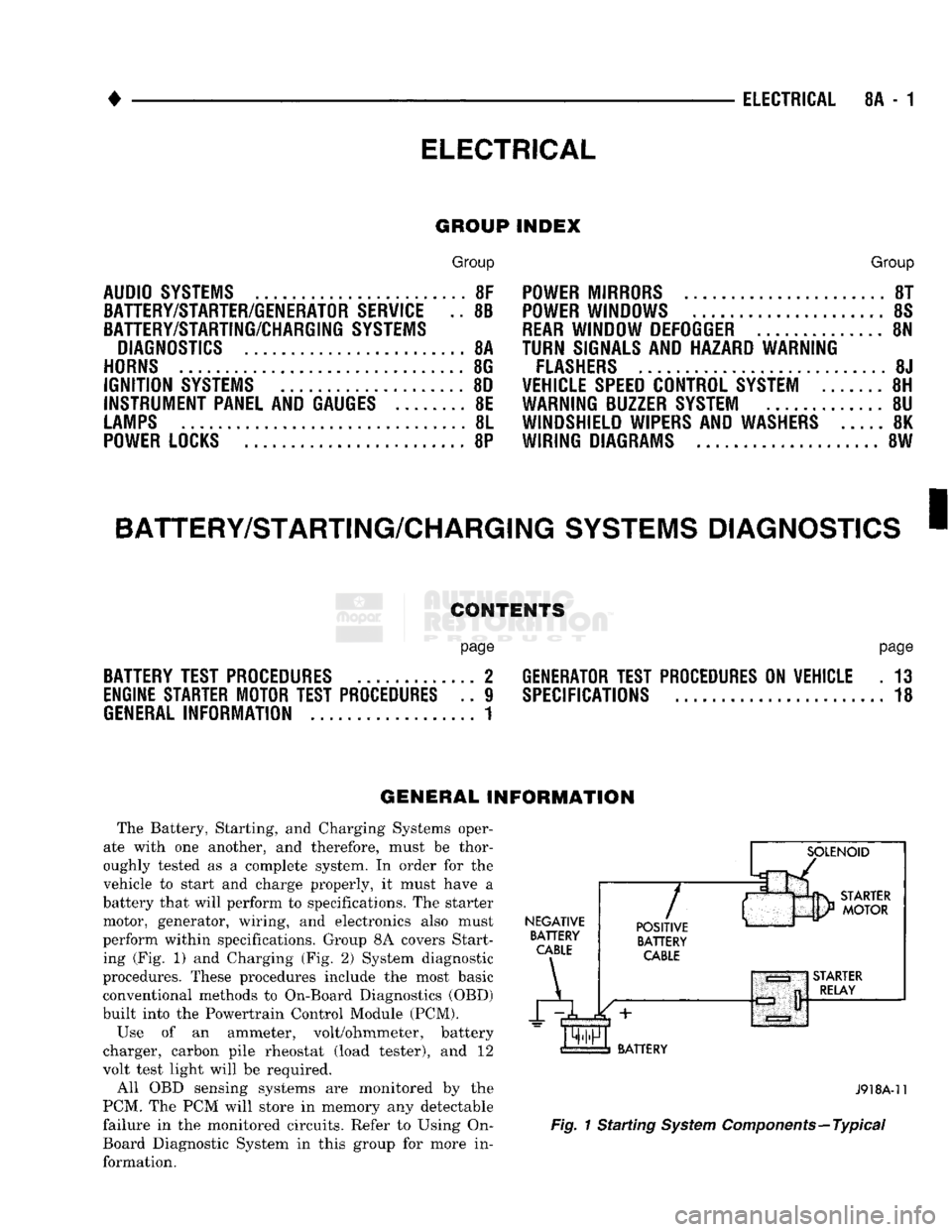
perform within specifications. Group 8A covers Start ing (Fig. 1) and Charging (Fig. 2) System diagnostic
procedures. These procedures include the most basic
conventional methods to On-Board Diagnostics (OBD)
built into the Powertrain Control Module (PCM).
Use of an ammeter, volt/ohmmeter, battery
charger, carbon pile rheostat (load tester), and 12
volt test light will be required.
All OBD sensing systems are monitored by the
PCM. The PCM will store in memory any detectable
failure in the monitored circuits. Refer to Using On-
Board Diagnostic System in this group for more in formation.
NEGATIVE
BATTERY
CABLE
A
7
POSITIVE
BATTERY
CABLE
BATTERY
J918A-11
Fig.
1 Starting
System
Components—Typical