service DODGE TRUCK 1993 Service Repair Manual
[x] Cancel search | Manufacturer: DODGE, Model Year: 1993, Model line: TRUCK, Model: DODGE TRUCK 1993Pages: 1502, PDF Size: 80.97 MB
Page 383 of 1502
8E
- 2
INSTRUMENT PANEL
AND
GAUGES
•
TEMPERATURE AND
OIL
INDICATING SYSTEM
(FIG.
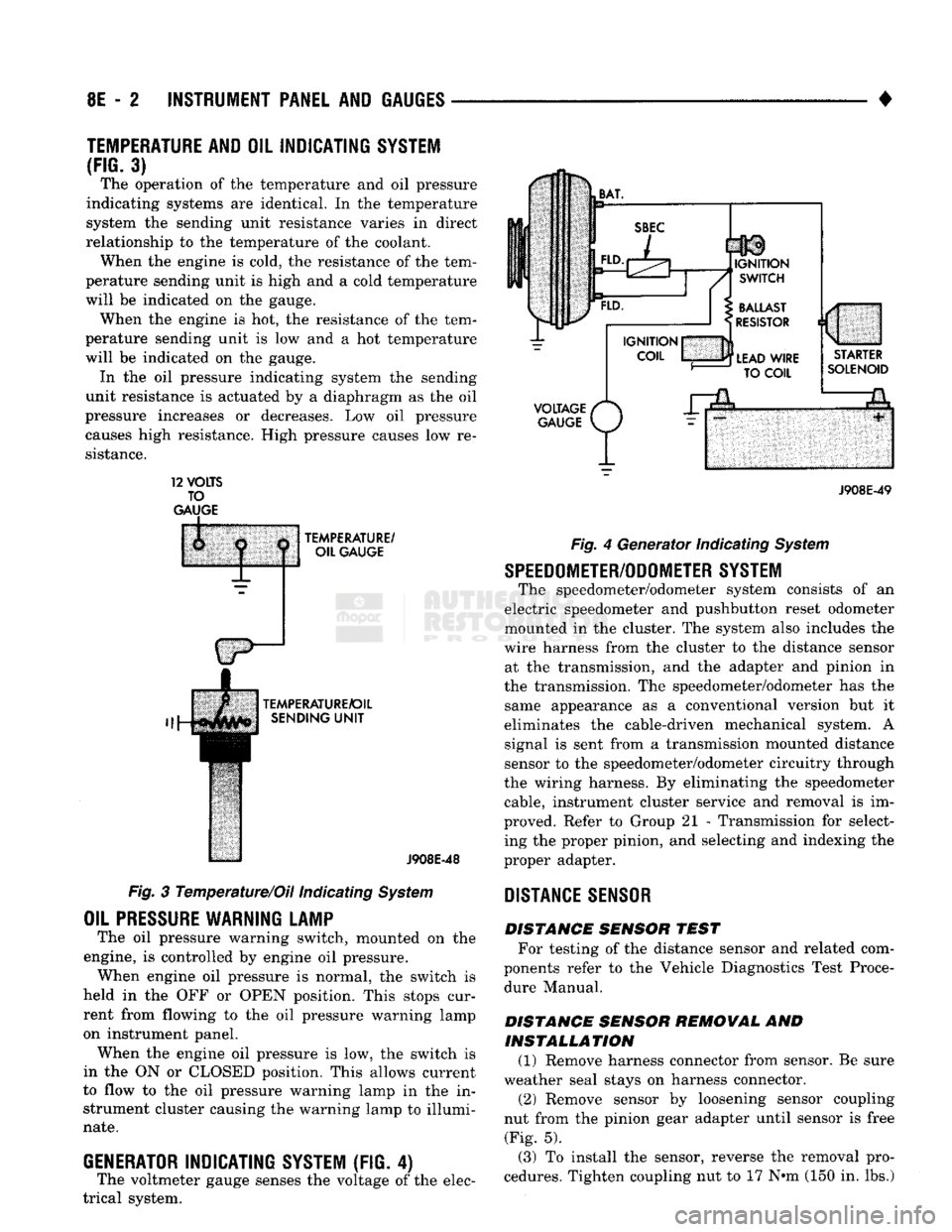
3) The operation of the temperature and oil pressure
indicating systems are identical. In the temperature
system the sending unit resistance varies in direct
relationship to the temperature of the coolant. When the engine is cold, the resistance of the tem
perature sending unit is high and a cold temperature
will be indicated on the gauge. When the engine is hot, the resistance of the tem
perature sending unit is low and a hot temperature
will be indicated on the gauge. In the oil pressure indicating system the sending
unit resistance is actuated by a diaphragm as the oil
pressure increases or decreases. Low oil pressure causes high resistance. High pressure causes low re
sistance. 12
VOLTS
TO
GAUGE
TEMPERATURE/
OIL GAUGE
TEMPERATURE/OIL SENDING
UNIT
J908E-48
Fig. 3 Temperature/Oil indicating System
OIL
PRESSURE
WARNING LAMP
The oil pressure warning switch, mounted on the
engine, is controlled by engine oil pressure. When engine oil pressure is normal, the switch is
held in the OFF or OPEN position. This stops cur
rent from flowing to the oil pressure warning lamp
on instrument panel. When the engine oil pressure is low, the switch is
in the ON or CLOSED position. This allows current
to flow to the oil pressure warning lamp in the in strument cluster causing the warning lamp to illumi
nate.
GENERATOR
INDICATING
SYSTEM
(FIG. 4)
The voltmeter gauge senses the voltage of the elec
trical system.
VOLTAGE
/*
GAUGE
P/
J908E-49 Fig. 4 Generator Indicating System
SPEEDOMETER/ODOMETER SYSTEM
The speedometer/odometer system consists of an
electric speedometer and pushbutton reset odometer
mounted in the cluster. The system also includes the
wire harness from the cluster to the distance sensor at the transmission, and the adapter and pinion in
the transmission. The speedometer/odometer has the same appearance as a conventional version but it
eliminates the cable-driven mechanical system. A signal is sent from a transmission mounted distance
sensor to the speedometer/odometer circuitry through
the wiring harness. By eliminating the speedometer cable, instrument cluster service and removal is im
proved. Refer to Group 21 - Transmission for select ing the proper pinion, and selecting and indexing the
proper adapter.
DISTANCE
SENSOR
DISTANCE SENSOR TEST For testing of the distance sensor and related com
ponents refer to the Vehicle Diagnostics Test Proce dure Manual.
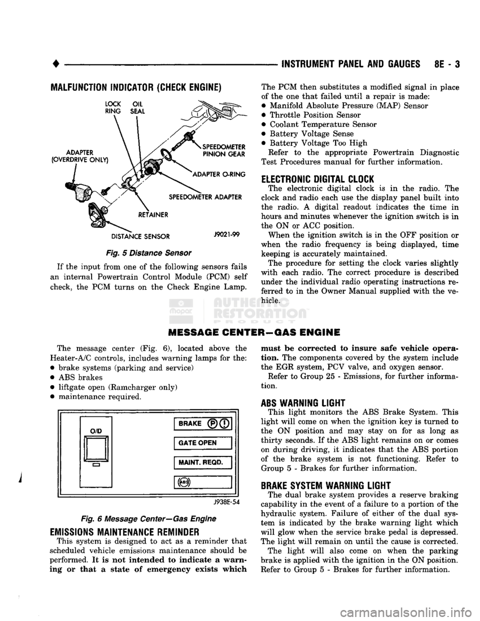
DISTANCE SENSOR REMOVAL AND INSTALLATION (1) Remove harness connector from sensor. Be sure
weather seal stays on harness connector. (2) Remove sensor by loosening sensor coupling
nut from the pinion gear adapter until sensor is free (Fig. 5).
(3) To install the sensor, reverse the removal pro
cedures. Tighten coupling nut to 17 N»m (150 in. lbs.)
Page 384 of 1502
•
INSTRUMENT PANEL
AND
GAUGES
8E - 3
MALFUNCTION INDICATOR (CHECK ENGINE)
Fig.
5
Distance Sensor
If
the
input from
one of the
following sensors fails
an internal Powertrain Control Module
(PCM)
self
check,
the PCM
turns
on the
Check Engine Lamp. The
PCM
then substitutes
a
modified signal
in
place
of
the one
that failed until
a
repair
is
made:
• Manifold Absolute Pressure (MAP) Sensor
• Throttle Position Sensor
• Coolant Temperature Sensor
• Battery Voltage Sense
• Battery Voltage
Too
High
Refer
to the
appropriate Powertrain Diagnostic
Test Procedures manual
for
further information.
ELECTRONIC DIGITAL CLOCK
The electronic digital clock
is in the
radio.
The
clock
and
radio each
use the
display panel built into
the radio.
A
digital readout indicates
the
time
in
hours
and
minutes whenever
the
ignition switch
is in
the
ON or ACC
position. When
the
ignition switch
is in the OFF
position
or
when
the
radio frequency
is
being displayed, time keeping
is
accurately maintained. The procedure
for
setting
the
clock varies slightly
with each radio.
The
correct procedure
is
described under
the
individual radio operating instructions
re
ferred
to in the
Owner Manual supplied with
the ve
hicle.
MESSAGE CENTER—GAS ENGINE
The message center
(Fig. 6),
located above
the
Heater-A/C controls, includes warning lamps
for the:
• brake systems (parking
and
service)
•
ABS
brakes • liftgate open (Ramcharger only)
• maintenance required.
O/D
BRAKE
(P)(7
GATE OPEN
MAINT
REQD.
J938E-54
Fig.
6
Message Center—Gas Engine
EMISSIONS
MAINTENANCE REMINDER
This system
is
designed
to act as a
reminder that
scheduled vehicle emissions maintenance should
be
performed.
It is not
intended
to
indicate
a
warn
ing
or
that
a
state
of
emergency exists which must
be
corrected
to
insure safe vehicle opera
tion.
The
components covered
by the
system include
the
EGR
system,
PCV
valve,
and
oxygen sensor. Refer
to
Group
25 -
Emissions,
for
further informa
tion.
ABS
WARNING
LIGHT
This light monitors
the ABS
Brake System. This
light will come
on
when
the
ignition
key is
turned
to
the
ON
position
and may
stay
on for as
long
as
thirty seconds.
If the ABS
light remains
on or
comes on during driving,
it
indicates that
the ABS
portion
of
the
brake system
is not
functioning. Refer
to
Group
5 -
Brakes
for
further information.
BRAKE
SYSTEM WARNING
LIGHT
The dual brake system provides
a
reserve braking
capability
in the
event
of a
failure
to a
portion
of the
hydraulic system. Failure
of
either
of the
dual sys
tem
is
indicated
by the
brake warning light which
will glow when
the
service brake pedal
is
depressed.
The light will remain
on
until
the
cause
is
corrected. The light will also come
on
when
the
parking
brake
is
applied with
the
ignition
in the ON
position.
Refer
to
Group
5 -
Brakes
for
further information.
Page 385 of 1502
8E
- 4
INSTRUMENT PANEL
AND
GAUGES
•
MESSAGE CENTER—DIESEL
ENGINE
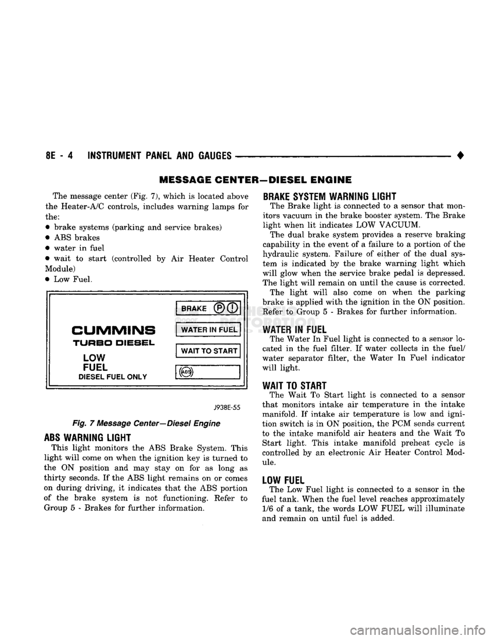
The message center (Fig. 7), which
is
located above
the Heater-A/C controls, includes warning lamps
for
the:
• brake systems (parking
and
service brakes)
• ABS brakes
• water
in
fuel
• wait
to
start (controlled
by Air
Heater Control
Module)
• Low Fuel.
BRAKE
CUMMINS
TURBO
DIESEL,
LOW
FUEL
DIESEL
FUEL ONLY WATER
IN
FUEL
WAIT
TO
START
J938E-55
Fig.
7
Message Center—Diesel Engine
ABS
WARNING LIGHT
This light monitors
the
ABS Brake System. This
light will come
on
when the ignition key
is
turned
to
the
ON
position
and may
stay
on for as
long
as
thirty seconds.
If
the ABS light remains
on or
comes
on during driving,
it
indicates that
the
ABS portion
of
the
brake system
is not
functioning. Refer
to
Group
5 -
Brakes
for
further information.
BRAKE
SYSTEM WARNING LIGHT
The Brake light
is
connected
to a
sensor that mon
itors vacuum
in
the brake booster system. The Brake
light when
lit
indicates LOW VACUUM. The dual brake system provides
a
reserve braking
capability
in
the event
of a
failure
to a
portion
of
the
hydraulic system. Failure
of
either
of the
dual sys
tem
is
indicated
by the
brake warning light which
will glow when
the
service brake pedal
is
depressed.
The light will remain
on
until
the
cause
is
corrected. The light will also come
on
when
the
parking
brake
is
applied with the ignition
in
the ON position. Refer
to
Group
5 -
Brakes
for
further information.
WATER
IN
FUEL
The Water
In
Fuel light
is
connected
to a
sensor lo
cated
in the
fuel filter.
If
water collects
in the
fuel/
water separator filter,
the
Water
In
Fuel indicator
will light.
WAIT
TO
START
The Wait
To
Start light
is
connected
to a
sensor
that monitors intake
air
temperature
in the
intake
manifold.
If
intake
air
temperature
is low and
igni
tion switch
is in
ON position,
the
PCM sends current
to
the
intake manifold
air
heaters
and the
Wait
To
Start light. This intake manifold preheat cycle
is
controlled
by an
electronic
Air
Heater Control Mod
ule.
LOW FUEL
The Low Fuel light
is
connected
to a
sensor
in the
fuel tank. When the fuel level reaches approximately 1/6
of a
tank,
the
words LOW FUEL will illuminate
and remain
on
until fuel
is
added.
Page 386 of 1502
•
INSTRUMENT PANEL
AND
GAUGES
8E - 5
CLUSTER
AND
GAUGE TEST
PROCEDURES
INDEX
page
Fuel Gauge
Circuit
Test
9
Fuel Tank Sending
Unit
Test
5
Oil Pressure Gauge
Circuit
Test
..............
9
Sending
Unit
(Sensor) Test
5
page
Speedometer
10
Temperature
Gauge
Circuit
Test
8
Voltage Gauge
Circuit
Test
10
Warning Lamp System Tests
6
CAUTION:
Disconnect
battery
negative cable,
in
en
gine compartment, before servicing instrument panel. When power
is
required
for
test purposes,
connect
battery
cable
(for
test only).
Disconnect battery negative cable after test
and before continuing service procedures.
SENDING
UNIT
(SENSOR) TEST
When
a
problem occurs with
a
cluster gauge,
be
fore disassembling
the
cluster
to
check
the
gauge, check
for a
defective sending unit (sensor)
or
wiring.
(1) Sending units
and
wiring
can be
checked
by
grounding
the
connector leads,
at the
sending unit,
in
the
vehicle.
CAUTION:
When connecting
an
input
terminal
to
ground,
Do Not
leave
the
connection grounded
for
more than
a
few
seconds.
(2) With
the
ignition
in the ON
position;
a
grounded input will cause
the oil,
fuel
or
tempera
ture gauge
to
read
at or
above maximum.
FUEL TANK SENDING
UNIT
TEST
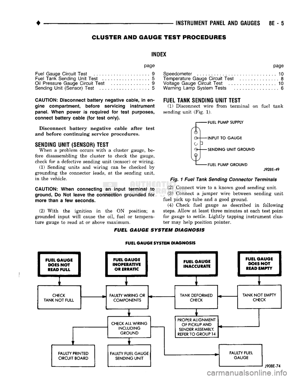
(1) Disconnect wire from terminal
on
fuel tank
sending unit (Fig.
1).
FUEL PUMP SUPPLY
INPUT
TO
GAUGE
SENDING
UNIT
GROUND
FUEL PUMP GROUND
J928E-49
Fig.
1
Fuel
Tank
Sending
Connector
Terminals
(2) Connect wire
to a
known good sending unit.
(3) Connect
a
jumper wire between sending unit
fuel pick
up
tube
and a
good ground.
(4) Check fuel gauge
as
described
in
following
steps.
Allow
at
least three minutes
at
each test point
for gauge
to
settle. Lightly tapping instrument clus
ter
may
help position pointer.
FUEL GAUGE SYSTEM DIAGNOSIS
FUEL GAUGE SYSTEM DIAGNOSIS FUEL GAUGE
DOES
NOT
READ
FULL FAULTY PRINTED
CIRCUIT BOARD FUEL GAUGE
INOPERATIVE OR ERRATIC FUEL GAUGE
INACCURATE
E
1
I
CHECK
FAULTY WIRING
OR
TANK DEFORMED
TANK
NOT
FULL COMPONENTS
CHECK
CHECK
ALL WIRING INCLUDING GROUND
i
FAULTY FUEL GAUGE SENDING
UNIT
i 1
FUEL
C
1
DOES
1
READ
1
pAUGE
I
>N0?
1
EMPTY
1
r
TANK
NOT
EMPTY
CHECK
PROPER
ALIGNMENT
OF PICKUP AND
SENDER
ASSEMBLY.
REFER
TO
GROUP
14
FAULTY FUEL
GAUGE
J908E-74
Page 388 of 1502
•
INSTRUMENT
PANEL
AND
GAUGES
8E - 7
STEERING PUMP
ENGINE
BLOCK
J9U9-74
Fig.
4 Oil
Pressure
Sending
Unit—Diesel
Engine
COMBINATION
OIL
UNIT
TEST
(FIG. 5)
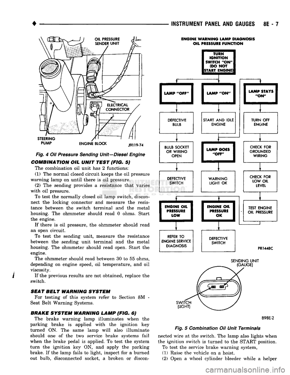
The combination oil unit has 2 functions:
(1) The normal closed circuit keeps the oil pressure
warning lamp on until there is oil pressure. (2) The sending provides a resistance that varies
with oil pressure.
To test the normally closed oil lamp switch, discon
nect the locking connector and measure the resis
tance between the switch terminal and the metal
housing. The ohmmeter should read 0 ohms. Start
the engine.
If there is oil pressure, the ohmmeter should read
an open circuit. To test the sending unit, measure the resistance
between the sending unit terminal and the metal
housing. The ohmmeter should read open, Start the engine.
The ohmmeter should read between 30 to 55 ohms,
depending on engine speed, oil temperature, and oil
viscosity.
If the previous results are not obtained, replace the
switch.
SEAT
BELT
WARNING
SYSTEM
For testing of this system refer to Section 8M -
Seat Belt Warning Systems.
BRAKE
SYSTEM
WARNING
LAMP
(FIG. 6) The brake warning lamp illuminates when the
parking brake is applied with the ignition key
turned ON. The same lamp will also illuminate should one of the two service brake systems fail
when the brake pedal is applied. To test the system
turn the ignition key ON, and apply the parking
brake. If the lamp fails to light, inspect for a burned
out bulb, disconnected socket, a broken or discon-
ENGINE WARNING LAMP DIAGNOSIS
OIL PRESSURE
FUNCTION
TURN
IGNITION
SWITCH
"OH"
(DO NOT
ISTART ENGINE)! LAMP "OFF'
LAMP "ON"
DEFECTIVE BULB START AND IDLE
ENGINE
BULB SOCKET OR WIRING OPEN LAMP STAYS
"ON" TURN OFF
ENGINE LAMP GOES
"OFF" DEFECTIVE
SWITCH CHECK FOR
GROUNDED WIRING
WARNING
LIGHT
OK CHECK FOR
LOW OIL LEVEL
ENGINE OIL
PRISSURi
LOW
REFER TO
ENGINE SERVICE DIAGNOSIS ENGIM
PRES
0
IE OIL
1
SURE
1
,K I
DEFECTIVE SWITCH TEST ENGINE
OIL PRESSURE
PR1448C
SWITCH
(LIGHT)
SENDING
UNIT
(GAUGE)
898E-2
Fig.
5 Combination Oil Unit Terminals
nected wire at the switch. The lamp also lights when
the ignition switch is turned to the START position. To test the service brake warning system,
(1) Raise the vehicle on a hoist.
(2) Open a wheel cylinder bleeder while a helper
Page 389 of 1502
8E
- 8 INSTRUMENT PANEL AND GAUGES
•
BRAKE
WARNING
LAMP
SWITCH TO BRAKE
WARNING LAMP
PR!
451
Fig.
6
Brake Warning
Lamp
Switch
depresses
the
brake pedal
and
observes
the
warning
lamp.
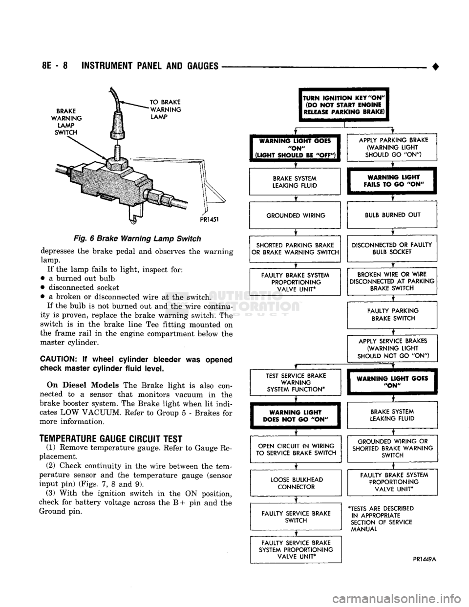
If
the
lamp fails
to
light, inspect
for:
•
a
burned
out
bulb
• disconnected socket
•
a
broken
or
disconnected wire
at the
switch. If
the
bulb
is not
burned
out and the
wire continu
ity
is
proven, replace
the
brake warning switch.
The
switch
is in the
brake line
Tee
fitting mounted
on
the frame rail
in the
engine compartment below
the
master cylinder.
CAUTION:
If
wheel cylinder bleeder
was
opened
check
master cylinder fluid level.
On Diesel Models
The
Brake light
is
also con
nected
to a
sensor that monitors vacuum
in the
brake booster system.
The
Brake light when
lit
indi cates
LOW
VACUUM. Refer
to
Group
5 -
Brakes
for
more information.
TEMPERATURE
GAUGE CIRCUIT TEST
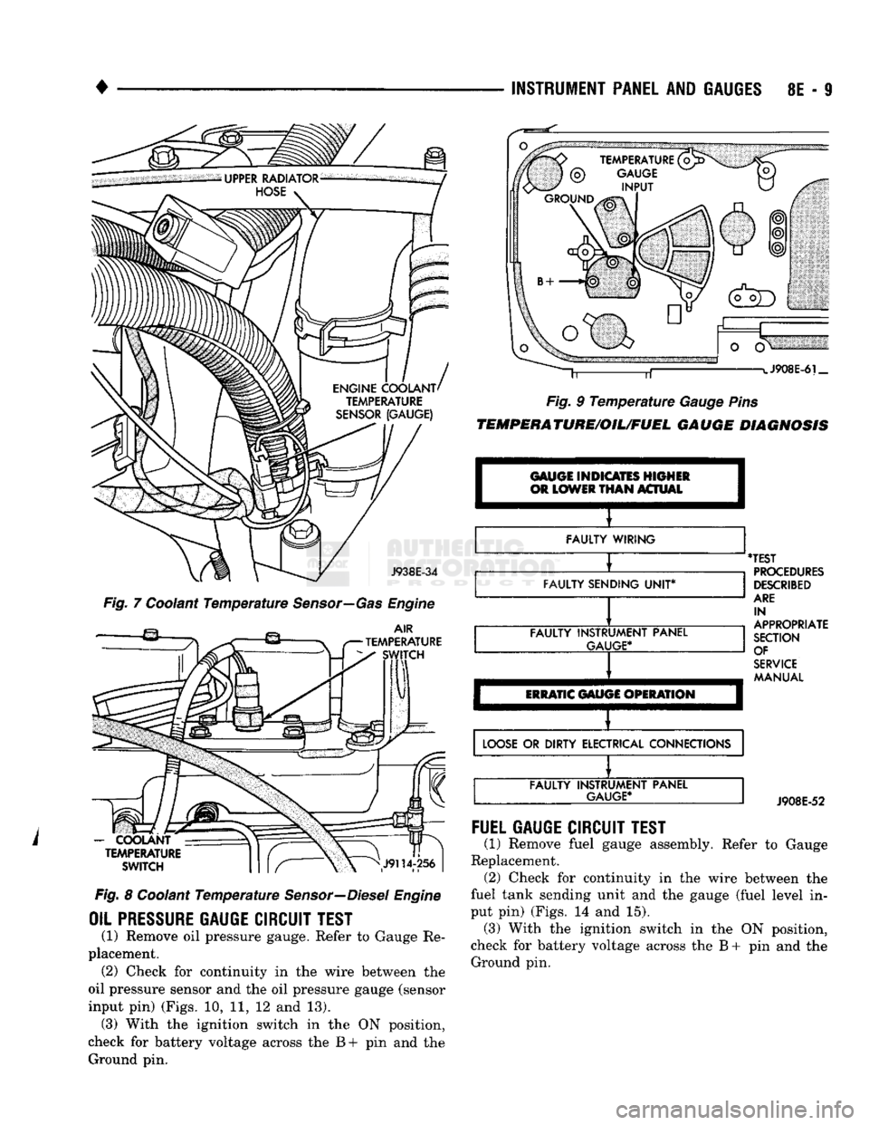
(1) Remove temperature gauge. Refer
to
Gauge
Re
placement. (2) Check continuity
in the
wire between
the
tem
perature sensor
and the
temperature gauge (sensor
input
pin)
(Figs.
7, 8 and 9).
(3) With
the
ignition switch
in the ON
position,
check
for
battery voltage across
the B + pin and the
Ground
pin.
(TURN
IGNITION
KEY
"ON"
(DO
NOT
START
ENGINE
I
RELEASE
PARKING
BRAKE)
I
I
[
WARNING
LIGHT
GOES
I
"ON"
I
1
(LIGHT
SHOULD
BE
"OFF")!
X
APPLY PARKING BRAKE (WARNING
LIGHT
SHOULD
GO "ON")
BRAKE
SYSTEM
LEAKING FLUID
X
WARNING
LIGHT
FAILS
TO GO "ON" GROUNDED WIRING
BULB
BURNED
OUT
SHORTED PARKING BRAKE
OR BRAKE WARNING SWITCH
X
DISCONNECTED
OR
FAULTY
BULB
SOCKET
FAULTY BRAKE SYSTEM PROPORTIONING VALVE
UNIT*
BROKEN
WIRE
OR
WIRE
DISCONNECTED
AT
PARKING
BRAKE
SWITCH
X
FAULTY PARKING
BRAKE
SWITCH
X
APPLY SERVICE BRAKES
(WARNING
LIGHT
SHOULD
NOT GO "ON")
JZ
X
TEST SERVICE BRAKE WARNING
SYSTEM FUNCTION*
X
WARNING
LIGHT
GOES
"ON"
WARNING
LIGHT
DOES
NOT GO "ON"
BRAKE
SYSTEM
LEAKING FLUID
OPEN CIRCUIT
IN
WIRING
TO SERVICE BRAKE SWITCH
X
GROUNDED WIRING
OR
SHORTED BRAKE WARNING SWITCH
LOOSE
BULKHEAD CONNECTOR
X
FAULTY BRAKE SYSTEM
PROPORTIONING VALVE
UNIT*
FAULTY SERVICE BRAKE SWITCH
X
•TESTS
ARE
DESCRIBED
IN APPROPRIATE
SECTION
OF
SERVICE MANUAL
FAULTY SERVICE BRAKE
SYSTEM PROPORTIONING VALVE
UNIT*
PR1449A
Page 390 of 1502
INSTRUMENT
PANEL
AND
GAUGES
8E - S
J938E-34
Fig. 7 Coolant Temperature Sensor—Gas Engine
AIR
TEMPERATURE SWITCH
-
COOLANT TEMPERATURE
SWITCH
Fig. 8 Coolant Temperature Sensor—Diesel Engine
OIL PRESSURE
GAUGE
CIRCUIT
TEST
(1) Remove oil pressure gauge. Refer to Gauge Re
placement. (2) Check for continuity in the wire between the
oil pressure sensor and the oil pressure gauge (sensor
input pin) (Figs. 10, 11, 12 and 13). (3) With the ignition switch in the ON position,
check for battery voltage across the B+ pin and the Ground pin. J908E-6i_
Fig. 9 Temperature Gauge Pins
TEMPERATURE/OIL/FUEL
GAUGE
DIAGNOSIS
GAUGE INDICATES HIGHER
OR
LOWER
THAN
ACTUAL I
FAULTY WIRING
FAULTY SENDING
UNIT*
FAULTY INSTRUMENT PANEL
GAUGE*
ERRATIC
GAUGE OPERATION
'TEST
PROCEDURES
DESCRIBED
ARE
IN
APPROPRIATE
SECTION OF
SERVICE
MANUAL
LOOSE
OR DIRTY ELECTRICAL CONNECTIONS FAULTY INSTRUMENT PANEL
GAUGE*
J908E-52
FUEL
GAUGE
CIRCUIT
TEST
(1) Remove fuel gauge assembly. Refer to Gauge
Replacement. (2) Check for continuity in the wire between the
fuel tank sending unit and the gauge (fuel level in
put pin) (Figs. 14 and 15). (3) With the ignition switch in the ON position,
check for battery voltage across the B + pin and the Ground pin.
Page 393 of 1502

8E
- 12
INSTRUMENT PANEL
AND
GAUGES
•
CLUSTER AND GAUGE
SERVICE
PROCEDURES
INDEX
page
Cluster Bezel
12
Cluster
Mask
and
Lens
12
Fuel Gauge
13
Instrument
Cluster Assembly
12
Lamp Bulb Replacement—Message Center
..... 15
CLUSTER
BEZEL
REMOVAL
(1) Disconnect negative cable from battery.
(2) Tape
or
cover steering column
to
prevent dam
age
to
paint.
(3) Remove
2
screws and remove map lamp.
CAUTION:
Map
lamp must
be
removed
to
prevent
damage
to
instrument panel.
(4) Remove
6
screws which attach cluster bezel
to
base panel (Fig.
1).
Make sure
the
screw below
the
Heater-A/C control
is
removed.
(5)
Place column shift lever
in
Position
"1".
(6) Remove bezel
by
pulling
top
edge rearward
to
clear brow. Disengage attaching clips around bottom
of bezel
and
complete removal
of
bezel.
(7)
If
bezel
is
equipped with
a
four wheel drive
in
dicator, remove bulb socket
as
bezel
is
removed.
(8) Disconnect message center wires.
INSTRUMENT
CLUSTER BEZEL
J938E-51
Fig.
1 instrument
Cluster
Bezel
INSTALLATION
(1) Connect bulb socket
for
four wheel drive indi
cator
if
equipped.
(2)
Connect message center wires.
(3) Engage attaching clips around bottom
of
bezel,
roll bezel into position.
(4) Install
6
mounting screws. page
Lamp Bulbs
. . 15
Printed
Circuit
Board
13
PRND21
Indicator
. 15
Specifications
15
Speedometer/Odometer
14
(5)
Install map lamp.
(6) Remove tape from steering column.
(7) Connect negative cable
to
battery.
CLUSTER
MASK AND LENS REMOVAL
(1) Disconnect negative cable from battery.
(2) Remove cluster bezel.
(3) Remove
8
screws holding mask
and
lens.
(4) Remove mask
and
lens.
INSTALLATION
(1) Position mask
and
lens.
(2) Install
8
screws.
(3) Install cluster bezel.
(4) Connect negative cable
to
battery.
INSTRUMENT CLUSTER ASSEMBLY
(Fig.
2)
REMOVAL
(1) Disconnect negative cable from battery.
(2) Tape
or
cover steering column
to
prevent dam
age
to
paint.
(3) Remove bezel.
(4) Remove lower steering column cover
4
screws.
(5)
Spread upper steering column cover
out of
the
locking tangs
and
slide downward. (6) Disconnect PRND21 actuator cable from steer
ing column
if
equipped.
(7) Loosen heater
and
A/C control. Pull rearward
to clear forward mount
on
cluster housing.
(8) Remove
6
screws that retain cluster. Pull clus
ter rearward
and
disconnect
2
large connectors.
(9) Remove cluster.
INSTALLATION
(1) Connect
2
large connectors
to
cluster.
(2) Position cluster
to
instrument panel and install
6 retaining screws.
(3) Install heater A/C control.
(4) Connect PRND21 actuator
to
steering column
if
equipped.
(5)
Position upper steering column cover
and
slide
upward until tangs snap into place.
Page 397 of 1502

8E - 16 INSTRUMENT PANEL AND GAUGES
• SWITCH AND
PANEL
COMPONENT
SERVICE
INDEX
page
Ash
Tray
20
Cigar
Lighter
........................ 20
Four
Wheel Drive
Indicator
19
Fuse
Block
and
Flashers
................... 19
Glove
Box 21
Heater A/C Control
17
page
Heater Control
16
Hood
Release
19
Illumination
Bulb Replacement
22
Message
Center Module
................... 18
Steering Column Lowering
and
Raising
16
Switches
17
DISCONNECT NEGATIVE CABLE FEOM
BATTERY IN ENGINE COMPAETMENT BE FORE SERVICING INSTRUMENT PANEL.
STEERING COLUMN LOWERING AND RAISING When servicing the instrument panel and the Low
ering and Raising of the steering column is required,
the following is the procedure for doing so: This procedure is not for removing and replac
ing the steering column. Refer to Group - 19 Steering of this manual for the removal and re
placement procedures.
LOWERING STEERING COLUMN
(1) Disconnect negative cable from battery.
(2)
Remove 3 toe plate nuts and washers (Fig. 1).
(3) Remove 1 toe plate screw.
(4) Remove 4 screws attaching lower steering col
umn cover and remove cover. The fuse block is at
tached to this cover and should be supported when cover is removed.
(5) Spread upper steering column cover out of lock
ing tangs and slide downward.
(6)
Disconnect cable from shift indicator bracket.
(7)
Remove 2 nuts and washers attaching steering
column bracket to instrument panel steering column support bracket.
(8)
Allow column to lower and rest on seat.
STEERING
COLUMN SUPPORT
WASHER
AND NUT
Fig.
1 Steering
Column
Mounting
RAISING STEERING COLUMN
(1) Raise steering column assembly against the in
strument panel support bracket. (2) Install 2 steering column bracket washers and
nuts (Finger Tighten Only).
CAUTION:
Check that
all
wiring
is
clear
and not
pinched.
(3) Tighten the 2 bracket nuts to 12 Nnn-(110 in.
lbs.) torque. (4) Slide toe plate into position, install attaching
screw, tighten to 4 N®m (35 in. lbs.).
(5) Install toe plate nuts and washers and tighten
to 23 N*m (200 in. lbs.).
(6)
Connect cable to shift indicator bracket.
(7)
Position upper steering column cover and slide
upward until tangs snap into place.
(8) Install fuse block to cover.
(9)
Position lower steering column cover and in
stall 4 attaching screws.
HEATER CONTROL
REMOVAL
(1) Remove map lamp.
(2) Remove cluster bezel (refer to Cluster Bezel Re
moval). (3) Remove 2 control attaching screws. (4) Pull control rearward.
(5) Disconnect illumination lamp, and wire connec
tions.
(6)
Disconnect control cables.
(7)
Remove control.
INSTALLATION
(1) Position control near panel.
(2) Connect control cables to control (see Heater
A/C Section). (3) Connect illumination lamp, and wire connec
tors.
(4) Push control into panel.
(5) Install 2 control mounting screws.
(6)
Install bezel.
(7)
Install map lamp.
Page 404 of 1502
AUDIO SYSTEMS
CONTENTS
SERVICE
PROCEDURES
page
.. 7
TEST PROCEDURES
page
.. 2
GENERAL
INFORMATION
For operation of the factory installed radios, refer
to the Owner Manual supplied with the vehicle. When connecting or disconnecting the Ignition Off
Draw (IOD) connector, it is important that the igni
tion switch be in the OFF position. Failure to place the ignition switch in the OFF po
sition can cause the radio display to become scram
bled when the IOD is disconnected. Connecting the IOD will correct the scrambled display.
INTERFERENCE
ELIMINATION
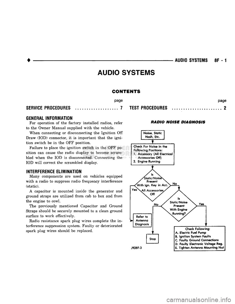
Many components are used on vehicles equipped
with a radio to suppress radio frequency interference (static). A capacitor is mounted inside the generator and
ground straps are utilized from cab to box and from
the engine to cowl. The previously mentioned Capacitor and Ground
Straps should be securely mounted to a clean ground
surface to work effectively. Radio resistance spark plug wires complete the in
terference suppression system. Faulty or deteriorated spark plug wires should be replaced.
RADIO NOISE DIAGNOSIS
Noise,
Static
Hash,
Etc.
Check
For Noise in
the
Following
Positions:
1.
Accessory (All Electrical
Accessories
Off)
2. Engine Running
Is
'Static/NoiseS
Present
'With
Ign.
Key in Acc.
Yes\^|j
Accessories/
Off
No
Refer
to
Antenna
Diagnosis
f
Stop
No
Is
Static/Noise Present
With Engine
Running?.
Yes
J928F-3
Check
Following:
A.
Electric
Fuel
Pump
B.
Ignition
System
Faults
C.
Faulty Ground Connections
D.
Faulty Electronic Voltage Reg.
E.
Tighten Antenna Mounting Nut