DODGE TRUCK 1993 Service Repair Manual
Manufacturer: DODGE, Model Year: 1993, Model line: TRUCK, Model: DODGE TRUCK 1993Pages: 1502, PDF Size: 80.97 MB
Page 761 of 1502
11
- 2
EXHAUST
SYSTEM
AND
INTAKE MANIFOLD
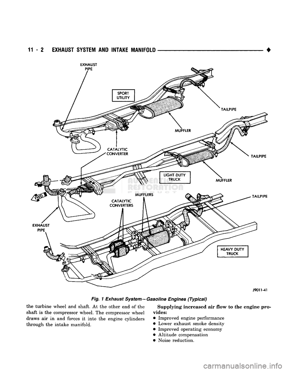
EXHAUST
J9011-41
Fig.
1
Exhaust
System—Gasoline
Engines
(Typical)
the turbine wheel
and
shaft.
At the
other
end of the
shaft
is the
compressor wheel.
The
compressor wheel
draws
air in and
forces
it
into
the
engine cylinders
through
the
intake manifold.
Supplying Increased air flow to the engine pro
vides:
• Improved engine performance
• Lower exhaust smoke density
• Improved operating economy
• Altitude compensation • Noise reduction.
Page 762 of 1502
EXHAUST
SYSTEM
AND
INTAKE MANIFOLD
11-3
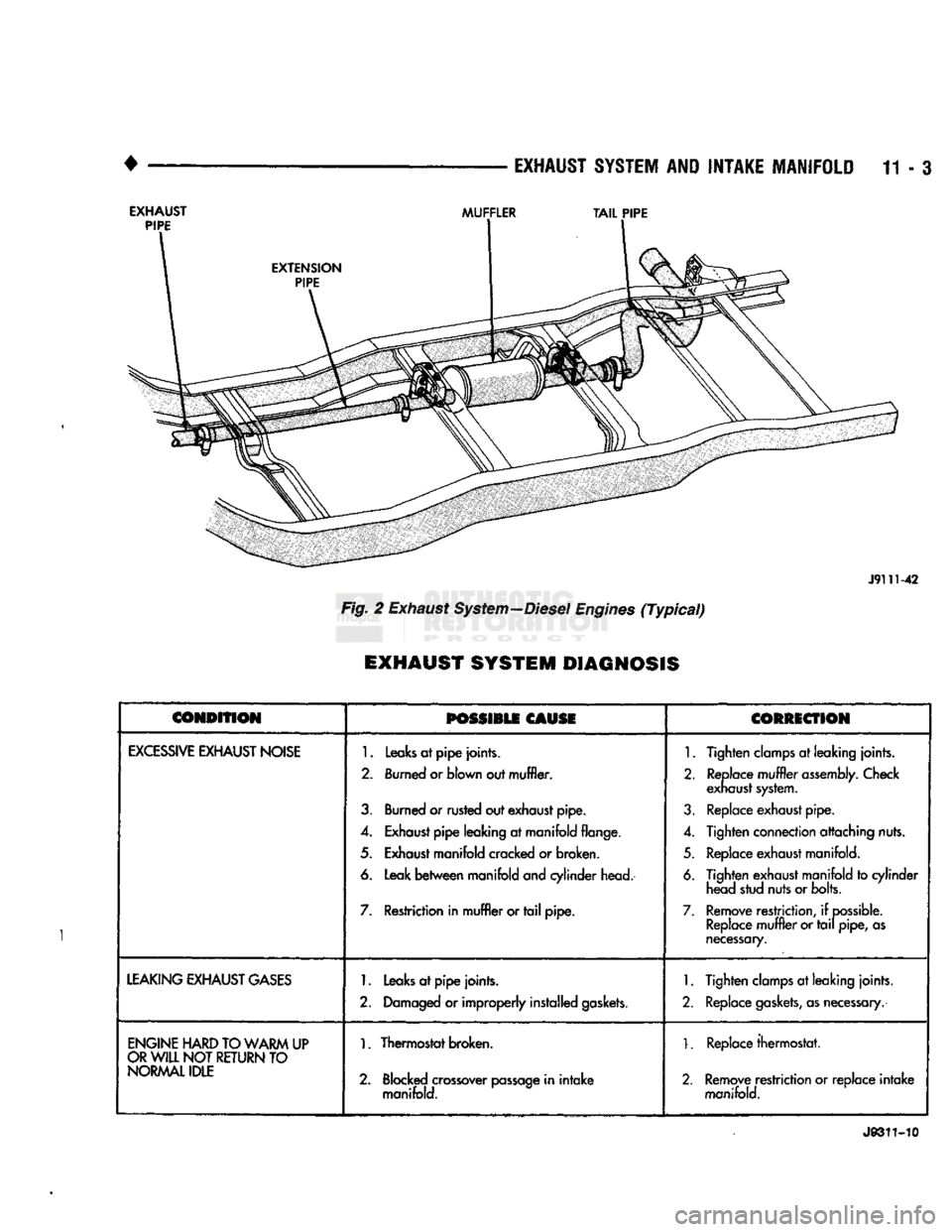
EXHAUST PIPE MUFFLER
TAIL
PIPE
J91U-42
Fig.
2
Exhaust System—Diesel Engines (Typical)
EXHAUST SYSTEM DIAGNOSIS
CONDITION
POSSIBLE
CAUSE CORRECTION
EXCESSIVE
EXHAUST
NOISE
1.
Leaks at pipe joints.
2.
Burned or blown out muffler.
3.
Burned or rusted out exhaust pipe.
4.
Exhaust pipe leaking at manifold flange.
5.
Exhaust manifold cracked or broken.
6. Leak between manifold and cylinder head.
7.
Restriction in muffler or tail pipe.
1.
Tighten clamps
at
leaking joints.
2.
Replace muffler assembly. Check exhaust system.
3.
Replace exhaust pipe.
4.
Tighten connection attaching nuts.
5.
Replace exhaust manifold.
6. Tighten exhaust manifold to cylinder head stud nuts or bolts.
7.
Remove restriction, if possible. Replace muffler or tail pipe,
as
necessary.
LEAKING
EXHAUST
GASES
1.
Leaks at pipe joints.
2.
Damaged or improperly installed gaskets.
1.
Tighten clamps at leaking joints.
2.
Replace gaskets, as necessary.
ENGINE
HARD
TO
WARM
UP
OR
WILL
NOT RETURN TO NORMAL
IDLE
1.
Thermostat broken.
2.
Blocked crossover passage in intake manifold.
1.
Replace thermostat.
2.
Remove restriction or replace intake manifold.
J9311-10
Page 763 of 1502
11
- 4
EXHAUST SYSTEM
AND
INTAKE MANIFOLD
•
SERVICE
PROCEDURES (GASOLINE ENGINES)
INDEX
page
Catalytic
Converters
4
Engine
Exhaust
Manifold
: . . . . 15
Exhaust
Heat
Shields
5
Exhaust
Pipe
4
page
Exhaust
Tailpipe
. 5
Intake Manifold
13
Mufflers
4
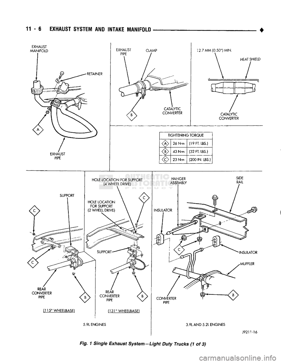
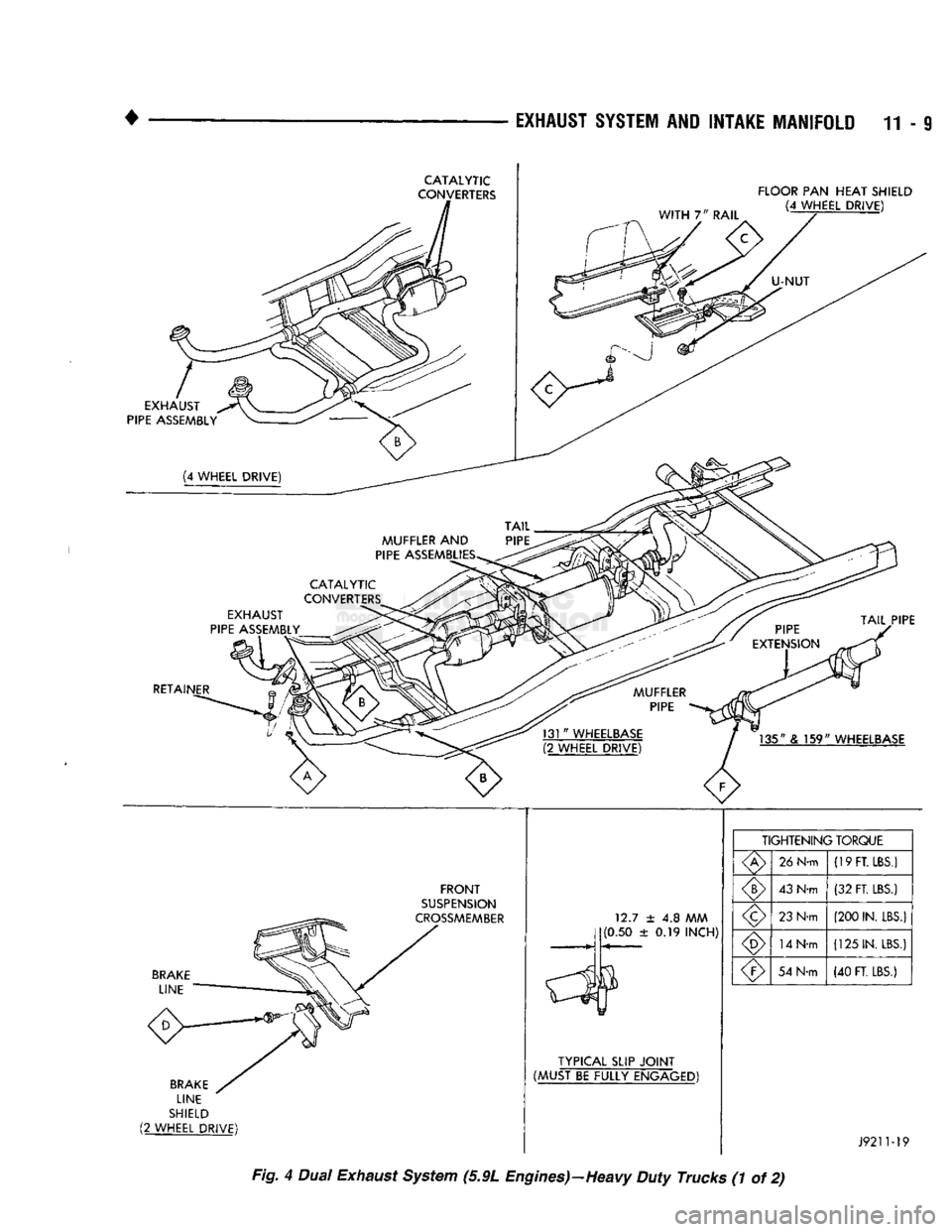
EXHAUST PIPE Refer
to
Figs.
1, 4, 5 and 6 for the
following proce
dure.
REMOVAL (1) Raise vehicle
on a
hoist.
(2) Apply penetrating
oil to
bolts
and
clamp nuts.
(3) Remove clamps, supports
and
bolts from
ex
haust pipe.
(4) Remove
the
exhaust pipe.
(5) Clean ends
of
pipes
to
assure mating
of all
parts.
(6) Discard rusted clamps, broken
or
worn supports
and attaching parts. Replace
a
component with orig
inal equipment parts,
or
equivalent. This will assure
proper alignment with other parts
in the
system
and
provide acceptable exhaust noise levels.
INSTALLATION (1) Assemble exhaust pipe, supports
and
clamps
loosely
to
permit proper alignment
of all
parts. (2) Position
the
exhaust pipe
for
proper clearance
with underbody parts.
(3)
On
models using ball-type connections, alter
nately tighten bolts
to
assure flanges
are
even
and
parallel.
(4) Tighten
all
clamp nuts, bolts
and
support
bracket nuts/bolts
to the
proper torques (Refer
to
Figs.
1, 4, 5 and 6).
(5) Lower
the
vehicle.
(6) Start
the
engine
and
check
for
leaks.
CATALYTIC CONVERTERS Refer
to
Figs.
1, 4, 5 and 6 for the
following proce
dure.
REMOVAL (1) Raise vehicle
on a
hoist.
(2) Apply penetrating
oil to
bolts
and
clamp nuts.
(3) Remove clamps, isolators
and
bolts.
(4) Remove
the
catalytic converter.
(5) Clean ends
of
pipes
and
muffler
to
assure mat
ing
of all
parts. (6) Discard rusted clamps, broken
or
worn isola
tors,
supports
and
attaching parts. Replace
a
compo
nent with original equipment parts,
or
equivalent. This will assure proper alignment with other parts
in
the system
and
provide acceptable exhaust noise lev
els.
INSTALLATION (1) Assemble converter, isolators
and
clamps
loosely
to
permit proper alignment
of all
parts. (2) Position
the
converter
for
proper clearance with
exhaust heat shields
and
underbody parts.
(3) Tighten
all
clamp nuts, bolts
and
support
bracket nuts/bolts
to the
proper torques (Refer
to
Figs.
1, 4, 5 and 6).
(4) Lower
the
vehicle.
(5) Start
the
engine
and
check
for
leaks.
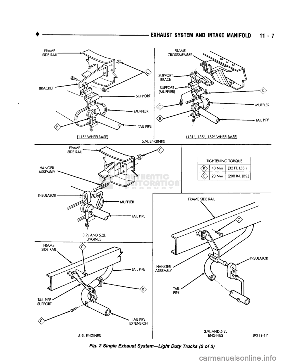
MUFFLERS Refer
to
Figs.
1, 2, 4, 5, 6 and 7 for the
following
procedure.
REMOVAL (1) Raise vehicle
on a
hoist.
(2) Apply penetrating
oil to
bolts
and
clamp nuts. (3) Remove clamps, isolators
and
bolts.
(4) Remove
the
muffler.
(5) Clean ends
of
pipes
and
muffler
to
assure mat
ing
of all
parts.
(6) Discard rusted clamps, broken
or
worn isola
tors,
supports
and
attaching parts. Replace
a
compo
nent with original equipment parts,
or
equivalent.
This will assure proper alignment with other parts
in
the system
and
provide acceptable exhaust noise lev
els.
INSTALLATION (1) Assemble muffler, isolators
and
clamps loosely
to permit proper alignment
of all
parts. (2) Position
the
muffler
for
proper clearance with
the underbody parts.
(3) Tighten
all
clamp nuts, bolts
and
support
bracket nuts/bolts
to the
proper torques (Refer
to
Figs.
1, 2, 4, 5, 6 and 7).
Page 764 of 1502
•
EXHAUST SYSTEM
AND
INTAKE MANIFOLD
11-5 (4) Lower the vehicle.
(5) Start the engine and check for leaks.
EXHAUST
TAILPIPE
Refer to Figs. 2, 4, 5, and 7 for the following pro
cedure.
REMOVAL (1) Raise vehicle on a hoist.
(2) Apply penetrating oil to bolts and clamp nuts.
(3) Remove clamps, isolators and bolts.
(4) Remove the exhaust tailpipe.
(5) Clean ends of pipes and muffler to assure mat
ing of all parts.
(6) Discard rusted clamps, broken or worn isola
tors,
supports and attaching parts. Replace a compo
nent with original equipment parts, or equivalent.
This will assure proper alignment with other parts in
the system and provide acceptable exhaust noise lev
els.
INSTALLATION (1) Assemble exhaust tailpipe, isolators and clamps
loosely to permit proper alignment of all parts. (2) Position the exhaust tailpipe for proper clear
ance with the underbody parts. (3) Tighten all clamp nuts, bolts and support
bracket nuts/bolts to the proper torques (Refer to
Figs.
2, 4, 5 and 7). (4) Lower the vehicle.
(5) Start the engine and check for leaks.
EXHAUST HEAT SHIELDS
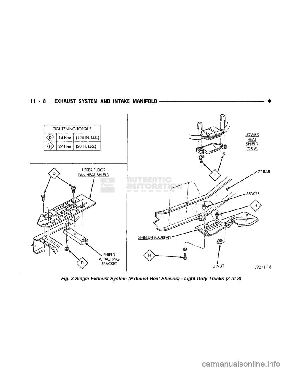
Refer to Figs. 3, 4 and 8 for the following proce
dure.
REMOVAL (1) Raise and support the vehicle.
(2) Remove the nuts or bolts holding the exhaust
heat shield to the floor pan, crossmember or bracket. (3) Slide the shield out around the exhaust system.
INSTALLATION (1) Position the exhaust heat shield to the floor
pan, crossmember or bracket and install the nuts or
bolts.
(2) Tighten the nuts and bolts to the proper torque
(refer to Figs. 3, 4 and 8).
(3) Lower the vehicle.
i
Page 765 of 1502
11
- 6
EXHAUST
SYSTEM
AID
INTAKE MANIFOLD
•
HOLE LOCATION FOR SUPPORT (4 WHEEL DRIVE)
REAR
CONVERTER PIPE
(115"
WHEELBASE1
(131"
WHEELBASE)
5.9L
ENGINES
HANGER
ASSEMBLY
CONVERTER PIPE
INSULATOR
MUFFLER
3.9L
AND
5.2L
ENGINES
J9211-16
Fig.
1
Single
Exhaust System—Light Duty Trucks (1 of 3)
Page 766 of 1502
•
EXHAUST
SYSTEM
AND
INTAKE MANIFOLD
11-7
INSULATOR
FRAME
SIDE
RAIL
3.9L
AND
5.2L
ENGINES
TAIL
PIPE
TAIL
PIPE
TAIL
PIPE
EXTENSION
5.9L
ENGINES HANGER
ASSEMBLY
TAIL
PIPE
FRAME
SIDE RAIL
INSULATOR
3.9L
AND
5.2L
ENGINES
J9211-17
Fig. 2 Single Exhaust System—Light Duty Trucks (2 of 3)
Page 767 of 1502
11 - 8 EXHAUST
SYSTEM
AND INTAKE MANIFOLD
Fig.
3
Single
Exhaust System (Exhaust Heat Shields)—Light Duty Trucks (3 of 3)
Page 768 of 1502
•
EXHAUST
SYSTEM AND INTAKE MANIFOLD 11-9
RETAINER
135" & 159" WHEELBASE
BRAKE
LINE
FRONT
SUSPENSION
CROSSMEMBER
BRAKE
LINE
SHIELD
(2 WHEEL DRIVE) 12.7 ± 4.8 MM
(0.50 ± 0.19 INCH)
TYPICAL
SLIP
JOINT
(MUST BE FULLY ENGAGED) TIGHTENING TORQUE
26
N-m
(19
FT. LBS.)
43
N-m
(32 FT. LBS.)
23
N-m (200
IN.
LBS.)
14
N-m
(125
IN. LBS.)
54
N-m (40
FT. LBS.)
J9211-19
Fig. 4 Dual Exhaust System (5.9L Engines)—Heavy Duty Trucks (1 of 2)
Page 769 of 1502
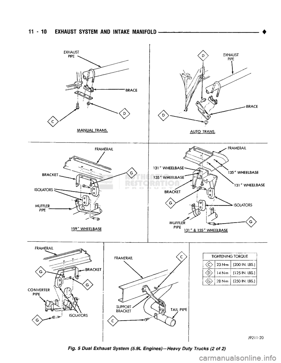
11
- 10
EXHAUST SYSTEM
AND
INTAKE MANIFOLD
EXHAUST
PIPE
BRACE
MANUAL
TRANS. EXHAUST
PIPE
BRACE
AUTO
TRANS.
BRACKET
ISOLATORS
MUFFLER
PIPE
FRAMERAIL
131
"
WHEELBASE
135"
WHEELBASE
FRAMERAIL
135"
WHEELBASE
131"
WHEELBASE
ISOLATORS
159"
WHEELBASE
MUFFLER
PIPE
131
"
& 135"
WHEELBASE
FRAMERAIL
BRACKET
CONVERTER PIPE
FRAMERAIL
TIGHTENING
TORQUE
23 N-m (200 IN.
LBS.)
14 N-m (125 IN.
LBS.)
28
N-m (250 IN.
LBS.)
J9211-20
Fig. 5 Dual Exhaust System (5.9L Engines)—Heavy Duty Trucks (2 of 2)
Page 770 of 1502
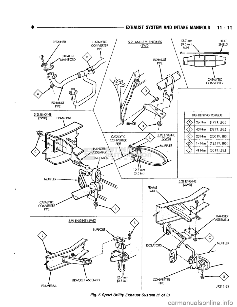
EXHAUST
SYSTEM
AND
INTAKE
MANIFOLD
11-11
RETAINER
CATALYTIC
CONVERTER
PIPE
HEAT
SHIELD
FRAMERAIL
J9211-22
Fig. 6 Sport
Utility
Exhaust System (1 of 3)