DODGE TRUCK 1993 Service Repair Manual
Manufacturer: DODGE, Model Year: 1993, Model line: TRUCK, Model: DODGE TRUCK 1993Pages: 1502, PDF Size: 80.97 MB
Page 751 of 1502
9
- 148 5.9L
(DIESEL) ENGINE
• Make sure the idler gear pin is installed in the lo
cating bore in the cylinder block. (2) Install the pump. Tighten the oil pump mount
ing bolts in two steps and in the sequence shown (Fig. 2).
• Step
1—Tighten
to 5 N«m (44 in. lbs.) torque.
• Step 2-Tighten to 24 N*m (18 ft. lbs.) torque. (3) The back plate on the pump seats against the
bottom of the bore in the cylinder block. When the
pump is correctly installed, the flange on the pump will not touch the cylinder block.
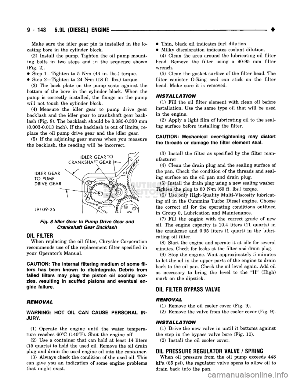
(4) Measure the idler gear to pump drive gear
backlash and the idler gear to crankshaft gear back lash (Fig. 8). The backlash should be 0.080-0.330 mm (0.003-0.013 inch). If the backlash is out of limits, re
place the oil pump drive gear and the idler gear.
(5) If the adjoining gear moves when you measure
the backlash, the reading will be incorrect.
Fig.
8
idler
Gear to
Pump
Drive Gear and Crankshaft Gear
Backlash
OIL FILTER
When replacing the oil filter, Chrysler Corporation
recommends use of the replacement filter specified in
your Operator's Manual.
CAUTION:
The
internal filtering medium
of
some
fil
ters
has
been known
to
disintegrate. Debris from
failed filters
may
plug
the
piston
oil
cooling noz
zles,
resulting
in
scuffed pistons
and
eventual
en
gine
failure.
REMOVAL
WARNING:
HOT OIL CAN
CAUSE PERSONAL
IN
JURY.
(1) Operate the engine until the water tempera
ture reaches 60°C (140°F). Shut the engine off.
(2) Use a container that can hold at least 14 liters
(15 quarts) to hold the used oil. Remove the oil drain
plug and drain the used engine oil into the container.
(3) Always check the condition of the used oil. This
can give you an indication of some engine problems
that might exist. • Thin, black oil indicates fuel dilution.
• Milky discoloration indicates coolant dilution.
(4) Clean the area around the lubricating oil filter
head. Remove the filter using a 90-95 mm filter
wrench.
(5) Clean the gasket surface of the filter head. The
filter canister O-Ring seal can stick on the filter
head. Make sure it is removed.
INSTALLATION (1) Fill the oil filter element with clean oil before
installation. Use the same type oil that will be used
in the engine.
(2) Apply a light film of lubricating oil to the seal
ing surface before installing the filter.
CAUTION:
Mechanical over-tightening
may
distort
the threads
or
damage
the filter
element seal.
(3) Install the filter as specified by the filter man
ufacturer. (4) Clean the drain plug and the sealing surface of
the pan. Check the condition of the threads and seal ing surface on the oil pan and drain plug.
(5) Install the drain plug using a new sealing washer.
Tighten the plug to 80 N-m (60 ft. lbs.) torque.
(6) Use only High-Quality Multi-Viscosity lubricat
ing oil in the Cummins Turbo Diesel engine. Choose
the correct oil for the operating conditions outlined in Group 0, Lubrication and Maintenance.
(7) Fill the enginfe with the correct grade of new
oil.
The engine capacity is i0.4 liters (11 quarts) in
the crankcase and 0.95 liters (1 quart) in the lubri cating oil filter. (8) Start the engine and operate it at idle for several
minutes. Check for leaks at the filter and drain plug.
(9) Stop the engine. Wait approximately 5 minutes
to let the oil in the upper parts of the engine to drain
back to the oil pan. Check the oil level again. Add oil as necessary to bring the level to the "H" (High)
mark on the dipstick.
OIL FILTER
BYPASS
VALWE
REMOVAL
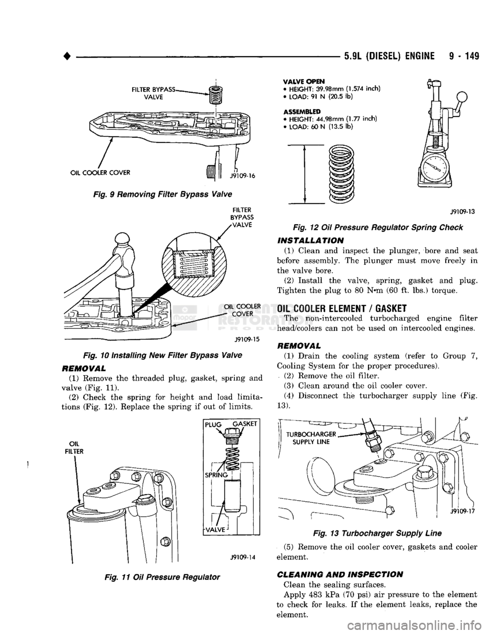
(1) Remove the oil cooler cover (Fig. 9). (2) Remove the valve from the cooler cover (Fig. 9).
INSTALLATION (1) Drive the new valve in until it bottoms against
the step in the bypass valve bore (Fig. 10).
(2) Install the oil cooler cover.
OIL PRESSURE REGULATOR VALVE
/
SPRING
When oil pressure from the oil pump exceeds 448
kPa (65 psi), the regulator valve opens to allow oil to
drain back into the pan.
Page 752 of 1502
5.9L
(DIESEL) ENGINE
9 - 149
FILTER
BYPASS-
VALVE
OIL COOLER COVER
Fig. 9
Removing
Filter
Bypass
Valve
n
J9109-16
FILTER
BYPASS
VALVE OIL COOLER
COVER
J9109-15
Fig. 10 Installing New
Filter
Bypass
Valve
REMOVAL
(1) Remove the threaded plug, gasket, spring and
valve (Fig. 11). (2) Check the spring for height and load limita
tions (Fig. 12). Replace the spring if out of limits.
OIL
FILTER PLUG GASKET
SPRING
J9109-14
Fig. 11 Oil
Pressure
Regulator
VALVE OPEN
•
HEIGHT:
39.98mm
(1.574
inch)
•
LOAD:
91 N (20.5 lb)
ASSEMBLED
•
HEIGHT:
44.98mm (1.77 inch) •
LOAD:
60 N (13.5 lb)
J9109-13
Fig. 12 Oil
Pressure
Regulator
Spring
Check
INSTALLATION
(1) Clean and inspect the plunger, bore and seat
before assembly. The plunger must move freely in
the valve bore.
(2) Install the valve, spring, gasket and plug.
Tighten the plug to 80 N*m (60 ft. lbs.) torque.
OIL COOLER ELEMENT
/
GASKET
The non-intercooled turbocharged engine filter
head/coolers can not be used on intercooled engines.
REMOVAL
(1) Drain the cooling system (refer to Group 7,
Cooling System for the proper procedures).
(2) Remove the oil filter.
(3) Clean around the oil cooler cover. (4) Disconnect the turbocharger supply line (Fig.
13).
J9109-17
Fig. 13 Turbocharger
Supply
Line
(5) Remove the oil cooler cover, gaskets and cooler
element.
CLEANING
AND
INSPECTION
Clean the sealing surfaces.
Apply 483 kPa (70 psi) air pressure to the element
to check for leaks. If the element leaks, replace the element.
Page 753 of 1502
9 - 150 5.9L
(DIESEL) ENGINE
•
INSTALLATION
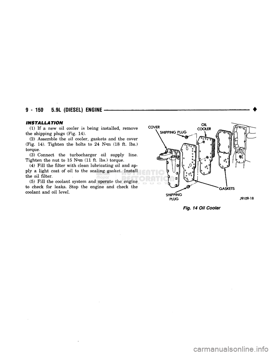
(1) If a new oil cooler is being installed, remove
the shipping plugs (Fig. 14). (2) Assemble the oil cooler, gaskets and the cover
(Fig. 14). Tighten the bolts to 24 N-m (18 ft. lbs.)
torque. (3) Connect the turbocharger oil supply line.
Tighten the nut to 15 N-m (11 ft. lbs.) torque. (4) Fill the filter with clean lubricating oil and ap
ply a light coat of oil to the sealing gasket. Install the oil filter. (5) Fill the coolant system and operate the engine
to check for leaks. Stop the engine and check the
coolant and oil level.
SHIPPING
PLUG
J9109-18
Fig.
14 Oil
Cooler
Page 754 of 1502
• 5.9L
(DIESEL) ENGINE
9 - 151
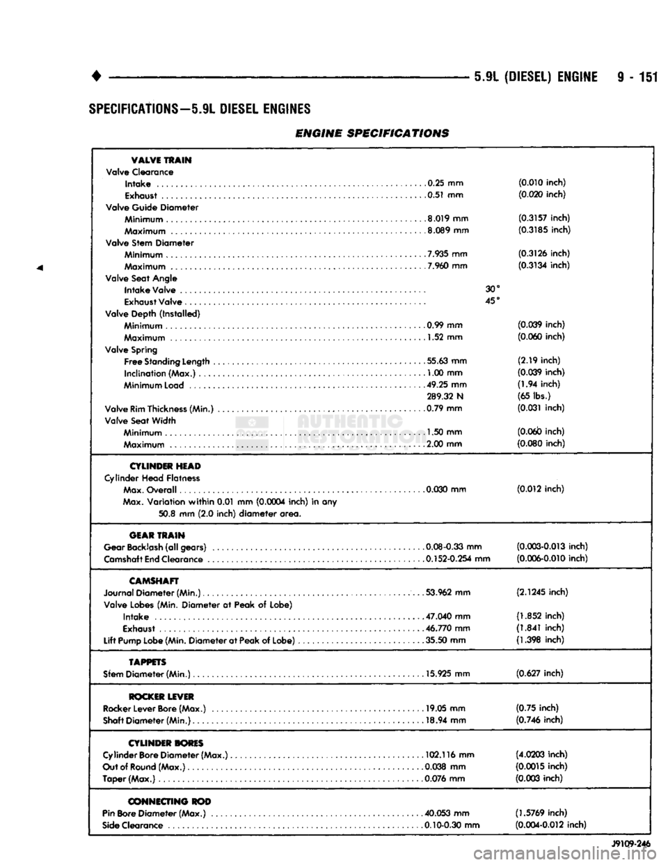
SPECIFICATIONS—5.9L DIESEL ENGINES
ENGINE SPECIFICATIONS
VALVE
TRAIN
Valve Clearance
Intake
.0.25 mm
(0.010 inch)
0.51 mm (0.020 inch)
Valve Guide Diameter
Minimum
8.019 mm
(0.3157 inch)
Maximum
.8.089 mm
(0.3185 inch)
Valve Stem Diameter
7.935
mm (0.3126 inch)
Maximum
7.960
mm
(0.3134 inch)
Valve Seat
Angle
Intake
Valve 30°
Exhaust
Valve 45°
Valve Depth (Installed)
Minimum
. .......... 0.99 mm (0.039 inch)
Maximum
1.52 mm
(0.060 inch)
Valve
Spring
Free
Standing
Length
55.63 mm
(2.19
inch)
Inclination (Max.) , 1.00 mm
(0.039 inch)
Minimum
Load
49.25 mm
(1.94
inch)
289.32 N (65 lbs.)
Valve
Rim
Thickness
(Min.) 0.79 mm
(0.031 inch)
Valve Seat Width
Minimum
1.50 mm
(0.06b inch)
Maximum
. 2.00 mm
(0.080 inch)
CYLINDER
HEAD
Cylinder
Head Flatness
Max.
Overall
0.030
mm (0.012 inch)
Max.
Variation
within
0.01 mm (0.0004 inch) in any
50.8
mm
(2.0
inch)
diameter
area.
GEAR
TRAIN
Gear
Backlash
(all gears) 0.08-0.33 mm
(0.003-0.013 inch)
Camshaft
End
Clearance 0.152-0.254 mm
(0.006-0.010 inch)
CAMSHAFT
Journal Diameter (Min.) 53.962 mm
(2.1245 inch)
Valve
Lobes
(Min. Diameter at Peak of Lobe)
Intake
.... 47.040 mm
(1.852 inch)
Exhaust
46.770 mm
(1.841 inch)
Lift
Pump
Lobe
(Min.
Diameter at
Peak
of Lobe) 35.50 mm
(1.398 inch)
TAPPETS
Sfem
Diameter (Min.) 15.925 mm
(0.627 inch)
ROCKER
LEVER
Rocker
Lever
Bore
(Max.) 19.05 mm
(0.75
inch)
Shaft
Diameter (Min.) 18.94 mm
(0.746 inch)
CYLINDER
TORES
Cylinder
Bore
Diameter (Max.) 102.116 mm
(4.0203 inch)
Out
of
Round
(Max.) . .0.038 mm
(0.0015 inch)
Taper (Max.)
0.076
mm
(0.003 inch)
CONNECTING
ROD
Pin
Bore
Diameter (Max.) . 40.053 mm (1.5769 inch)
Side
Clearance 0.10-0.30 mm
(0.004-0.012 inch)
J9109-246
Page 755 of 1502
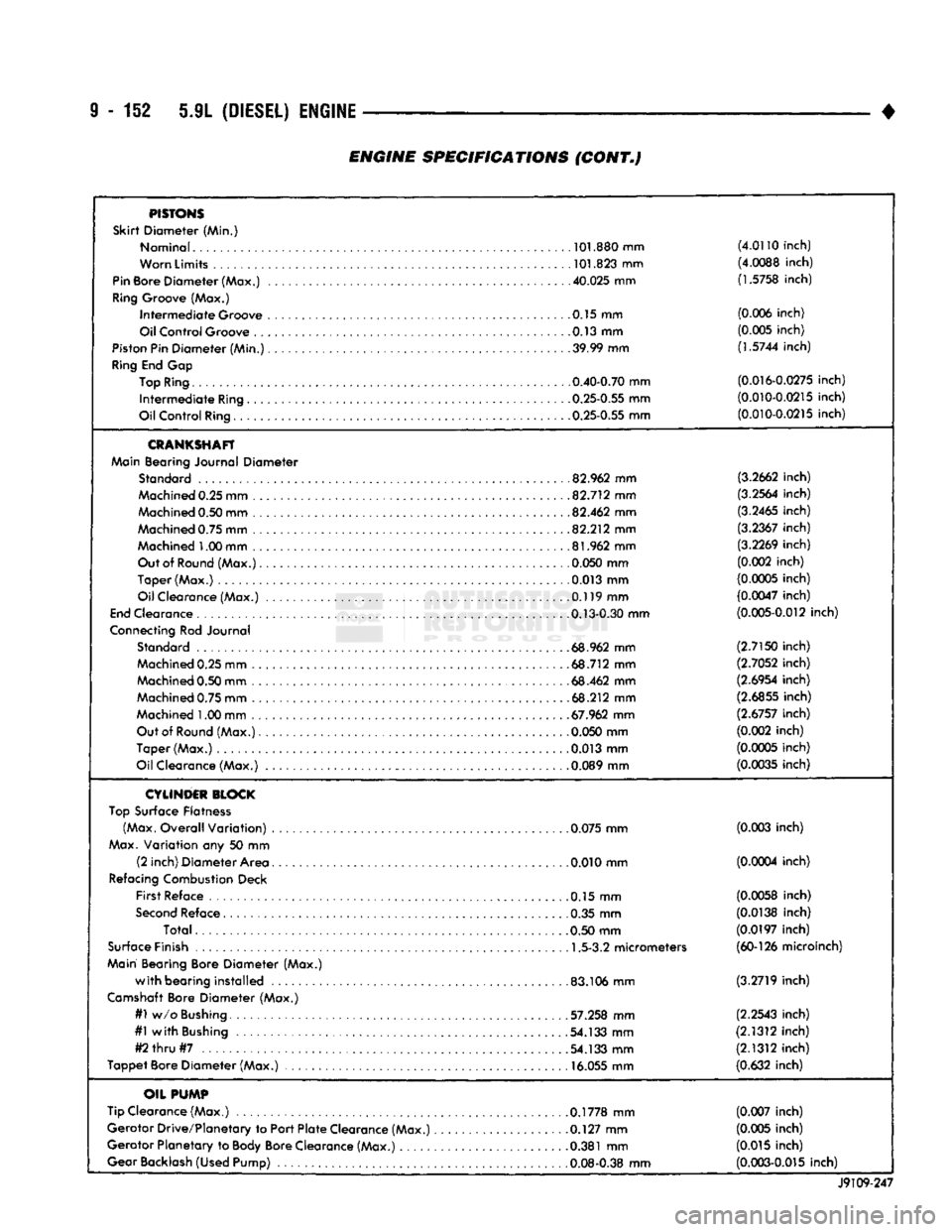
9 - 152 5.9L (DIESEL) ENGINE
ENGINE
SPECIFICATIONS (CONT.)
PISTONS
Skirt
Diameter (Min.)
Nominal
.....
. .
101.880
mm
(4.0110
inch)
Worn
Limits
101.823
mm
(4.0088
inch)
Pin
Bore Diameter (Max.)
40.025
mm
(1.5758
inch)
Ring
Groove (Max.) Intermediate Groove 0.15 mm
(0.006
inch)
Oil Control Groove 0.13 mm
(0.005
inch)
Piston
Pin Diameter (Min.)
39.99
mm (1.5744 inch)
Ring
End Gap
Top
Ring
0.40-0.70
mm
(0.016-0.0275
inch)
Intermediate
Ring
..
.0.25-0.55
mm
(0.010-0.0215
inch)
Oil Control
Ring
0.25-0.55
mm
(0.010-0.0215
inch)
CRANKSHAFT
Main
Bearing Journal Diameter
Standard
82.962
mm
(3.2662
inch)
Machined
0.25 mm
.82.712
mm
(3.2564
inch)
Machined
0.50 mm
82.462
mm
(3.2465
inch)
Machined
0.75 mm
82.212
mm
(3.2367
inch)
Machined
1.00 mm
.81.962
mm
(3.2269
inch)
Out
of
Round
(Max.)
0.050
mm
(0.002
inch)
Taper (Max.) 0.013 mm
(0.0005
inch)
Oil Clearance (Max.)
...
...
.0.119
mm
(0.0047
inch)
End
Clearance .
.0.13-0.30
mm
(0.005-0.012
inch)
Connecting
Rod Journal
Standard
.68.962
mm
(2.7150
inch)
Machined
0.25 mm
68.712
mm
(2.7052
inch)
Machined
0.50 mm
68.462
mm
(2.6954
inch)
Machined
0.75 mm
.68.212
mm
(2.6855
inch)
Machined
1.00 mm
.67.962
mm
(2.6757
inch)
Out
of
Round
(Max.)
0.050
mm
(0.002
inch)
Taper (Max.)
.0.013
mm
(0.0005
inch)
Oil Clearance (Max.)
0.089
mm
(0.0035
inch)
CYLINDER
BLOCK
Top
Surface Flatness
(Max.
Overall Variation)
0.075
mm
(0.003
inch)
Max.
Variation any 50 mm (2 inch) Diameter Area 0.010 mm
(0.0004
inch)
Refacing
Combustion
Deck First Reface 0.15 mm
(0.0058
inch)
Second
Reface 0.35 mm
(0.0138
inch)
Total .0.50 mm
(0.0197
inch)
Surface
Finish
1.5-3.2
micrometers
(60-126
microinch)
Main
Bearing Bore Diameter (Max.)
with
bearing installed
.
.83.106
mm
(3.2719
inch)
Camshaft
Bore Diameter (Max.)
#1
w/o
Bushing
57.258
mm
(2.2543
inch)
#1
with
Bushing
.54.133
mm
(2.1312
inch)
#2
thru
#7
54.133
mm
(2.1312
inch)
Tappet Bore Diameter (Max.)
16.055
mm
(0.632
inch)
OIL
PUMP
Tip Clearance (Max.)
0.1778
mm
(0.007
inch)
Gerotor Drive/Planetary to Port Plate Clearance (Max.)
.
.0.127
mm
(0.005
inch)
Gerotor Planetary to
Body
Bore Clearance (Max.)
.0.381
mm
(0.015
inch)
Gear
Backlash
(Used Pump)
0.08-0.38
mm
(0.003-0.015
inch)
J9109-247
Page 756 of 1502
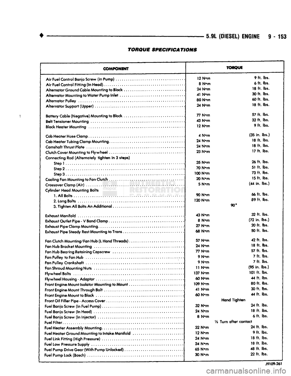
5.9L
(DIESEL)
ENGINE
9-153
TORQUE
SPECIFICATIONS
COMPONENT
Air
Fuel
Control
Banjo Screw (In Pump) ....
Air
Fuel
Control
Fitting
(In
Head)
Alternator
Ground Cable Mounting to
Block
Alternator
Mounting to
Water
Pump
Inlet
..
Alternator
Pulley
Alternator
Support
(Upper)
Battery
Cable
(Negative)
Mounting to Block ,
Belt
Tensioner
Mounting
Block
Heater
Mounting
Cab
Heater
Hose
Clamp
Cab
Heater
Tubing
Clamp Mounting.......
Camshaft
Thrust
Plate
Clutch Cover Mounting to
Flywheel
...
Connecting Rod
(Alternately
tighten
in 3 steps) Step 1
Step 2
Step 3 .
Cooling Fan Mounting to
Fan
Clutch
Crossover
Clamp (Air)
Cylinder
Head
Mounting Bolts
1.
All
Bolts....
2.
Long
Bolts
.........
3.
Tighten
All
Bolts
An
Additional
Exhaust
Manifold
Exhaust
Outlet
Pipe
- V
Band
Clamp
Exhaust
Pipe
Clamp Mounting
Exhaust
Pipe
Steady
Rest
Mounting to Trans .
Fan
Clutch Mounting/Fan Hub
(L
Hand
Threads)..
Fan Hub
Bracket
Mounting
Fan Hub Bearing
Retaining
Capscrew
Fan
Pulley
to
Fan
Hub
Fan
Pulley
Crankshaft .
Fan
Shroud
Mounting Nuts
Flywheel
Bolts
Flywheel
Housing
- Adaptor
Front
Engine
Mount Isolator Mounting to Mount..
Front
Engine
Mount Through Bolt
Front
Engine
Mount to Block
Front
Oil
Filler
Pipe
-
Access
Cover
Fuel
Banjo Screw (In
Fuel
Pump)
Fuel
Banjo Screw (In
Head)
Fuel
Banjo Screw (In
Injector)
Fuel
Filter
Fuel
Heater
Assembly
Mounting
Fuel
Heater
Ground Mounting to
Intake
Manifold
Fuel
Link
Fitting
(High Pressure)
Fuel
Low Pressure Supply
Fuel
Pump
Drive
Gear
(With
Pump
Unlocked)
Fuel
Pump Lock (Bosch)
TORQUE
12 N-m 9 ft. lbs.
8 N-m 6 ft. lbs.
24 N-m 18 ft. lbs.
41 N*m 30 ft. lbs.
80 N-m 60 ft. lbs.
24 N-m 18 ft. lbs.
77 N-m 57 ft. lbs.
43 N-m 32 ft. lbs.
12 N-m 9 ft. lbs.
4 N-m (35 in. lbs.)
24 N-m 18 ft. lbs.
24 N-m 18 ft. lbs.
23 N-m 17 ft. lbs.
35 N-m 26 ft. lbs.
70 N-m 51 ft. lbs.
100 N-m 73 ft. lbs.
20 N-m 15 ft. lbs.
5
N-m (44 in. lbs.)
90 N-m 66 ft. lbs.
120 N-m 89 ft. lbs.
90°
43 N-m 32 ft. lbs.
8 N-m (72 in. lbs.)
27 N-m 20 ft. lbs.
68 N-m 50 ft. lbs.
57 N-m 42 ft. lbs.
24 N-m 18 ft. lbs.
77 N-m 57 ft. lbs.
9 N-m 7 ft. lbs.
9 N-m 7 ft. lbs.
11 N-m (95 in. lbs.)
137 N-m 101 ft. lbs.
60 N-m 44 ft. lbs.
109 N-m 80 ft. lbs.
41 N-m 30 ft. lbs.
60 N-m 44 ft. lbs.
Hand
Tighten
32 N-m 24 ft. lbs.
24 N-m 18 ft. lbs.
8 N-m 6 ft. lbs.
Vi
Turn
after
contact
32 N-m 24 ft. lbs.
12 N-m 9 ft. lbs.
24 N-m 18 ft. lbs.
24 N-m 18 ft. lbs.
65 N-m 48 ft. lbs.
30 N-m 22 ft. lbs.
J9109-261
Page 757 of 1502
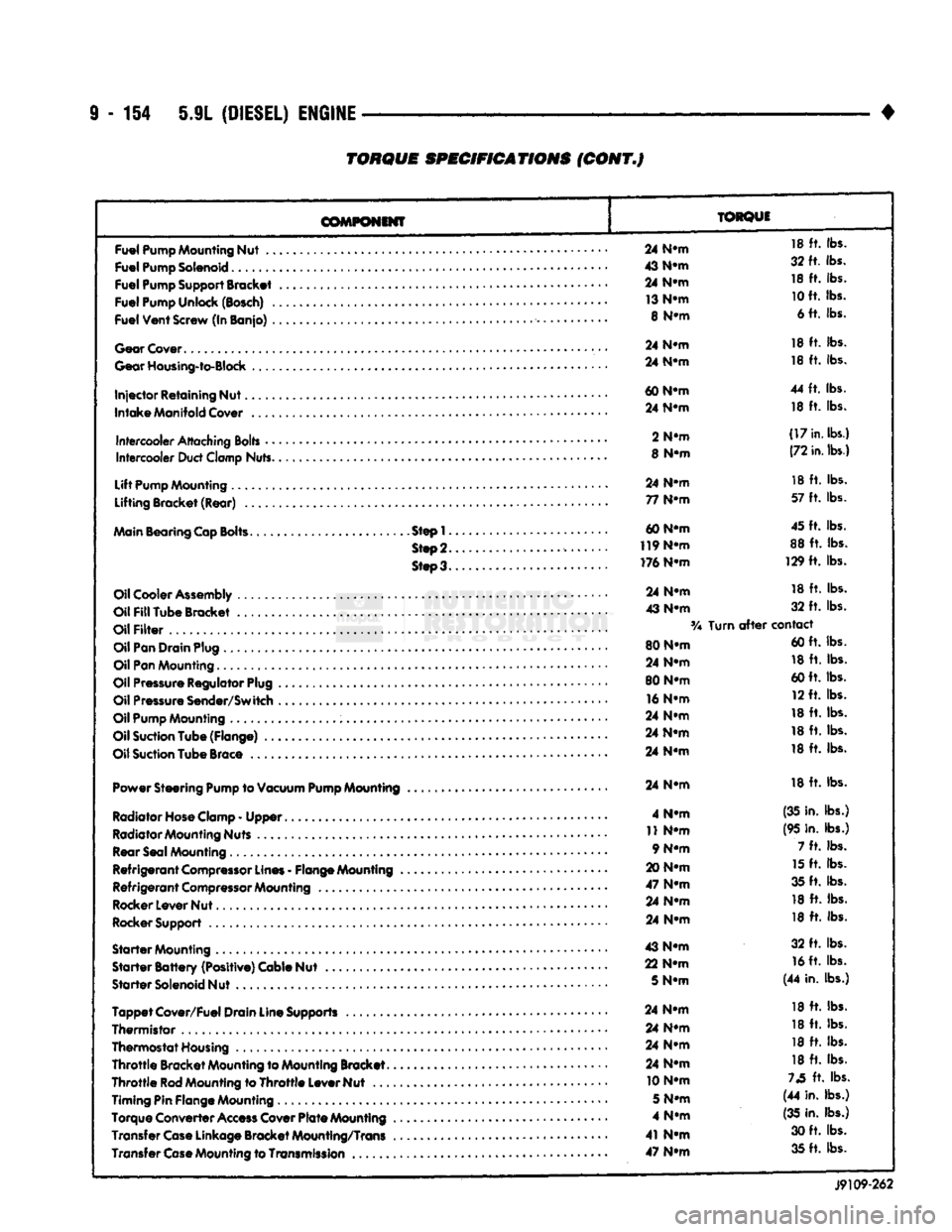
9
- 154 5.9L
(DIESEL)
ENGINE
TORQUE
SPECIFICATIONS
(CONT.J
COMPONENT
TORQUE
Fuel
Pump
Mounting
Nut
..
Fuel
Pump
Solenoid
Fuel
Pump
Support
Bracket
Fuel
Pump
Unlock
(Bosch)
.
Fuel
Vent
Screw
(In Banjo)
.
Gear
Cover
Gear
Housing-to-Block
Injector
Retaining Nut.
Intake
Manifold
Cover
Intercooler
Attaching
Bolts
•
•
Intercooler
Duct
Clamp
Nuts.
Lift
Pump
Mounting
Lifting Bracket (Rear)
..
Main
Bearing
Cap
Bolts.
Step!.
Step
2.
Steo3.
Oil
Cooler
Assembly
Oil
Fill
Tube Bracket
Oil
Filter
Oil
Pan
Drain
Plug
Oil
Pan
Mounting.........
Oil
Pressure
Regulator
Plug
Oil
Pressure
Sender/Switch
Oil
Pump
Mounting
Oil
Suction
Tube (Flange)
..
Oil
Suction
Tube
Brace
Power Steering
Pump
to
Vacuum
Pump
Mounting
Radiator Hose Clamp
-
Upper
Radiator Mounting Nuts Rear Seal Mounting
Refrigerant
Compressor
Lines
-
Flange Mounting
Refrigerant
Compressor
Mounting
Rocker Lever Nut
Rocker Support
Starter
Mounting
Starter
Battery
(Positive) Cable Nut
Starter
Solenoid Nut
Tappet
Cover/Fuel Drain Line Supports
Thermistor
,
Thermostat Housing
Throttle
Bracket Mounting to Mounting Bracket.
Throttle
Rod
Mounting to
Throttle
Lever Nut
...
Timing Pin Flange Mounting
Torque Converter
Access
Cover
Plate
Mounting
Transfer
Case
Linkage Bracket Mounting/Trans Transfer
Case
Mounting to
Transmission
..
24
N-m
18
ft.
lbs.
43
N-m
32 ft. lbs.
24
N-m
18
ft.
lbs.
13
N-m
10
ft. lbs.
8
N-m
6 ft. lbs.
24
N-m
18
ft.
lbs.
24
N-m
18
ft.
lbs.
60
N-m
44
ft.
lbs.
24
N-m
18
ft.
lbs.
2
N-m
(17
in.
lbs.)
8
N-m
(72
in.
lbs.)
24
N-m
18
ft.
lbs.
77
N-m
57
ft.
lbs.
60 N-m 45 ft. lbs.
119
N-m
88
ft.
lbs.
176 N-m 129
ft.
lbs.
24
N-m
18
ft.
lbs.
43
N-m
32
ft.
lbs.
Turn
after
contact
80 N-m 60 ft. lbs.
24
N-m
18
ft.
lbs.
80 N-m 60 ft. lbs.
16
N-m
12 ft. lbs.
24
N-m
18
ft.
lbs.
24
N-m
18
ft.
lbs.
24
N-m
18
ft.
lbs.
24
N-m
18
ft.
lbs.
4
N-m
(35 in. lbs.)
11
N-m
(95 in. lbs.)
9 N-m 7
ft.
lbs.
20
N-m
15
ft.
lbs.
47
N-m
35 ft. lbs.
24
N-m
18
ft.
lbs.
24
N-m
18
ft.
lbs.
43
N-m
32
ft.
lbs.
22
N-m
16
ft. lbs.
5
N-m
(44 in. lbs.)
24
N-m
18
ft.
lbs.
24
N-m
18
ft.
lbs.
24
N-m
18
ft.
lbs.
24
N-m
18
ft.
lbs.
10 N-m
73
ft.
lbs.
5
N-m
(44 in. lbs.)
4
N-m
(35
in. lbs.)
41
N-m
30 ft. lbs.
47
N-m
35 ft. lbs.
J9109-262
Page 758 of 1502
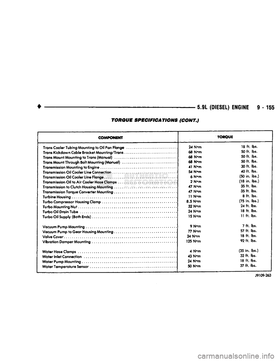
5.9L
(DIESEL)
ENGINE
9 - 155
TORQUE SPECIFICATIONS (CONT.)
COMPONENT
TORQUE
24 N-m 18 ft. lbs.
Trans
Kickdown Cable
Bracket
Mounting/Trans
68 N-m 50 ft. lbs.
68 N-m 50 ft. lbs.
68 N-m 50 ft. lbs.
41 N-m 30 ft. lbs.
54 N-m 40 ft. lbs.
Transmission
Oil Cooler
Line
Flange........
......... .. ......
6
N-m
(50
in.
lbs.)
Transmission
Oil to Air Cooler
Hose
Clamps
2
N-m
(18 in. lbs.)
Transmission
to
Clutch
Housing
Mounting
• 47 N-m
35 ft. lbs.
Transmission
Torque
Converter
Mounting
47 N-m 35 ft. lbs.
Turbine
Housing
11
N-m 8 ft. lbs.
Turbo
Compressor
Housing
Clamp
8.5 N-m (75
in.
lbs.)
Turbo
Mounting
Nut 32 N-m 24 ft. lbs.
Turbo
Oil
Drain
Tube
• 24 N-m
18 ft. lbs.
Turbo
Oil
Supply
(Both
Ends)
.
15
N-m
11
ft.
lbs.
Vacuum
Pump
Mounting
9
N-m
7 ft. lbs.
Vacuum Pump to
Gear
Housing
Mounting
77 N-m 57 ft. lbs.
Valve
Cover.
24 N-m
18 ft. lbs.
Vibration
Damper
Mounting
125 N-m
92 ft. lbs.
Water
Hose
Clamps
4 N-m (35
in.
lbs.)
Water
Inlet
Connection
43 N-m
32 ft. lbs.
Water
Pump
Mounting
24 N-m
18 ft. lbs.
Water
Temperature
Sensor
50 N-m 37 ft. lbs.
J9109-263
Page 759 of 1502

Page 760 of 1502
•
EXHAUST SYSTEM
AND
INTAKE MANIFOLD
11-1
CONTENTS
page
EXHAUST SYSTEM DIAGNOSIS
3
GENERAL
INFORMATION
1
SERVICE
PROCEDURES (DIESEL ENGINES)
. 17
page
SERVICE
PROCEDURES (GASOLINE ENGINES)
. 4
SPECIFICATIONS
27
GENERAL INFORMATION
EXHAUST SYSTEM
The gasoline engine exhaust system consists
of en
gine exhaust manifolds, exhaust pipe(s), catalytic converter(s), extension pipe(s), exhaust heat shields,
muffler(s)
and
exhaust tailpipe
(Fig. 1).
The diesel engine exhaust system consists
of an en
gine exhaust manifold, turbocharger, exhaust pipe,
extension pipe, muffler
and
exhaust tailpipe
(Fig. 2).
The engine exhaust manifolds
on
gasoline engines
are equipped with ball flange outlets
to
assure
a
tight seal
and
strain free connections. The exhaust system must
be
properly aligned
to
prevent stress, leakage
and
body contact.
If the
sys
tem contacts
any
body panel,
it may
amplify objec
tionable noises from
the
engine
or
body. When inspecting
an
exhaust system, critically
in
spect
for
cracked
or
loose joints, stripped screw
or
bolt threads, corrosion damage
and
worn, cracked
or
broken hangers. Replace
all
components that
are
badly corroded
or
damaged.
DO NOT
attempt
to re
pair. When replacement
is
required,
use
original equip
ment parts
(or
their equivalent). This will assure
proper alignment
and
provide acceptable exhaust
noise levels.
CAUTION:
Avoid
application
of
rust
prevention
compounds
or
undercoating materials
to
exhaust
system
floor
pan
exhaust
heat
shields.
Light
overs-
pray
near
the
edges
is
permitted. Application
of
coating
will
result
in
excessive
floor
pan
tempera
tures
and
objectionable
fumes.
CATALYTIC CONVERTER (GASOLINE ENGINES)
The stainless steel catalytic converter body
is de
signed
to
last
the
life
of the
vehicle. Excessive heat
can result
in
bulging
or
other distortion,
but
exces sive heat will
not be the
fault
of the
converter.
If un-
burned fuel enters
the
converter, overheating
may
occur.
If a
converter
is
heat-damaged, correct
the
cause
of the
damage
at the
same time
the
converter is replaced. Also, inspect
all
other components
of the
exhaust system
for
heat damage.
Unleaded gasoline must
be
used
to
avoid contami
nating
the
catalyst core.
EXHAUST HEAT SHIELDS (GASOLINE ENGINES)
Exhaust heat shields
are
needed
to
protect both
the
vehicle
and the
environment from
the
high tempera
tures developed
by the
catalytic converter.
The
com
bustion reaction facilitated
by the
catalyst releases additional heat
in the
exhaust system. Under severe
operating conditions,
the
temperature increases
in
the area
of the
reactor. Such conditions
can
exist
when
the
engine misfires
or
otherwise does
not
oper ate
at
peak efficiency.
DO NOT
remove spark plug
wires from plugs
or by any
other means short
out
cylinders. Failure
of the
catalytic converter
can
occur
due
to a
temperature increase caused
by
unburned
fuel passing through
the
converter. Do
not
allow
the
engine
to
operate
at
fast idle
for
extended periods (over
5
minutes). This condition
may result
in
excessive temperatures
in the
exhaust system
and on the
floor
pan.
EXHAUST GAS RECIRCULATION
(EGR)—(GASOLINE ENGINES)
To assist
in the
control
of
oxides
of
nitrogen
(NOx)
in engine exhaust,
all
engines
are
equipped with
an
exhaust
gas
recirculation system.
The use of
exhaust
gas
to
dilute incoming air/fuel mixtures lowers peak
flame temperatures during combustion, thus limiting
the formation
of NOx.
Exhaust gases
are
taken from openings
in the ex
haust
gas
crossover passage
in the
intake manifold. Refer
to
Group
25,
Emission Control Systems
for
complete description, diagnosis
and
service proce
dures
of the
exhaust
gas
recirculation system
and
components.
TURBOCHARGER
(5.9L
DIESEL ENGINE)
A turbocharger
is
used
to
force more
air
into
the
engine cylinders. Exhaust
gas
energy
is
used
to
turn
EXHAUST SYSTEM
AND
INTAKE MANIFOLD