DODGE TRUCK 1993 Service Repair Manual
Manufacturer: DODGE, Model Year: 1993, Model line: TRUCK, Model: DODGE TRUCK 1993Pages: 1502, PDF Size: 80.97 MB
Page 801 of 1502
14 FRAME AND BUMPERS
•
RB530
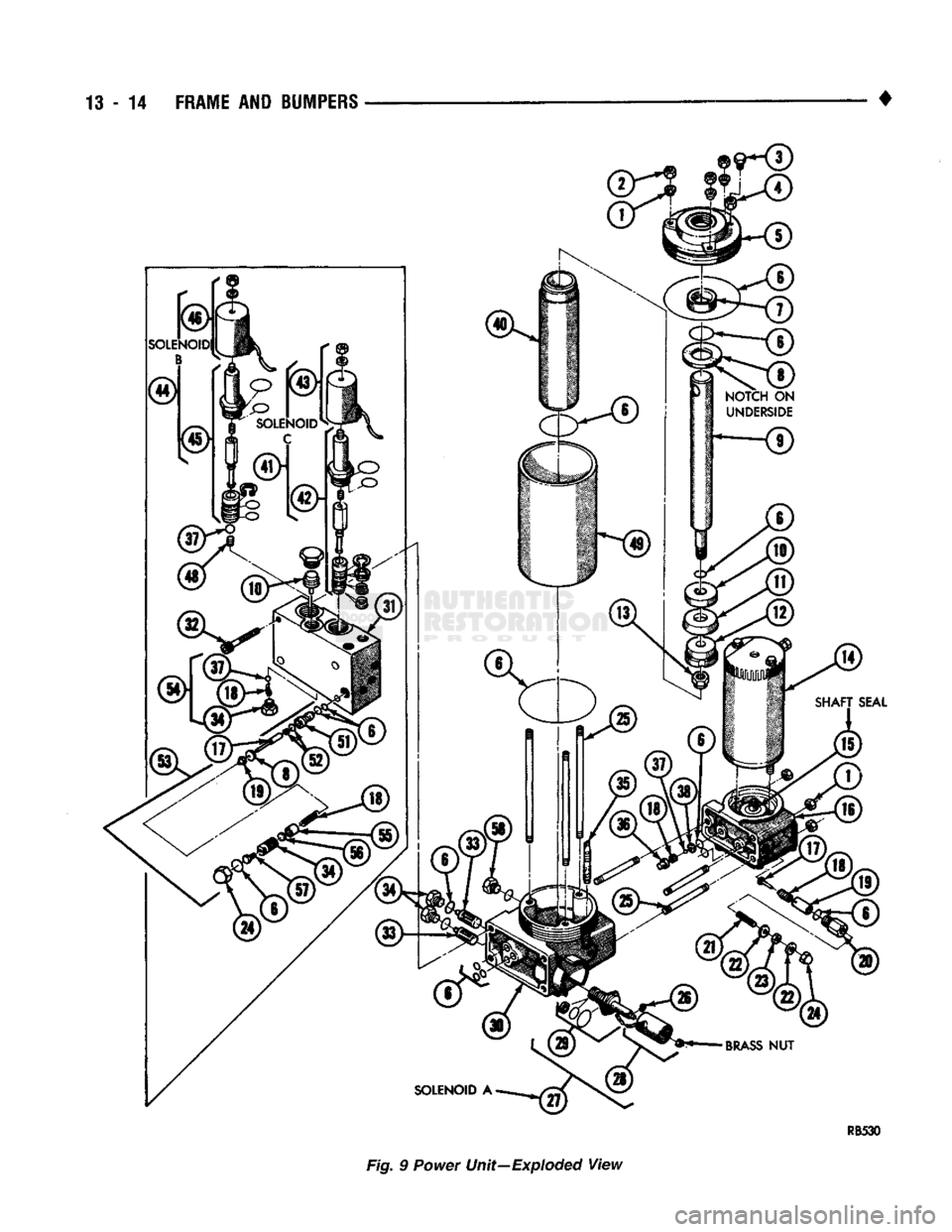
Fig. 9 Power Unit—Exploded
View
Page 802 of 1502
FRAME
AND
BUMPERS
13 - 15
LEGEND
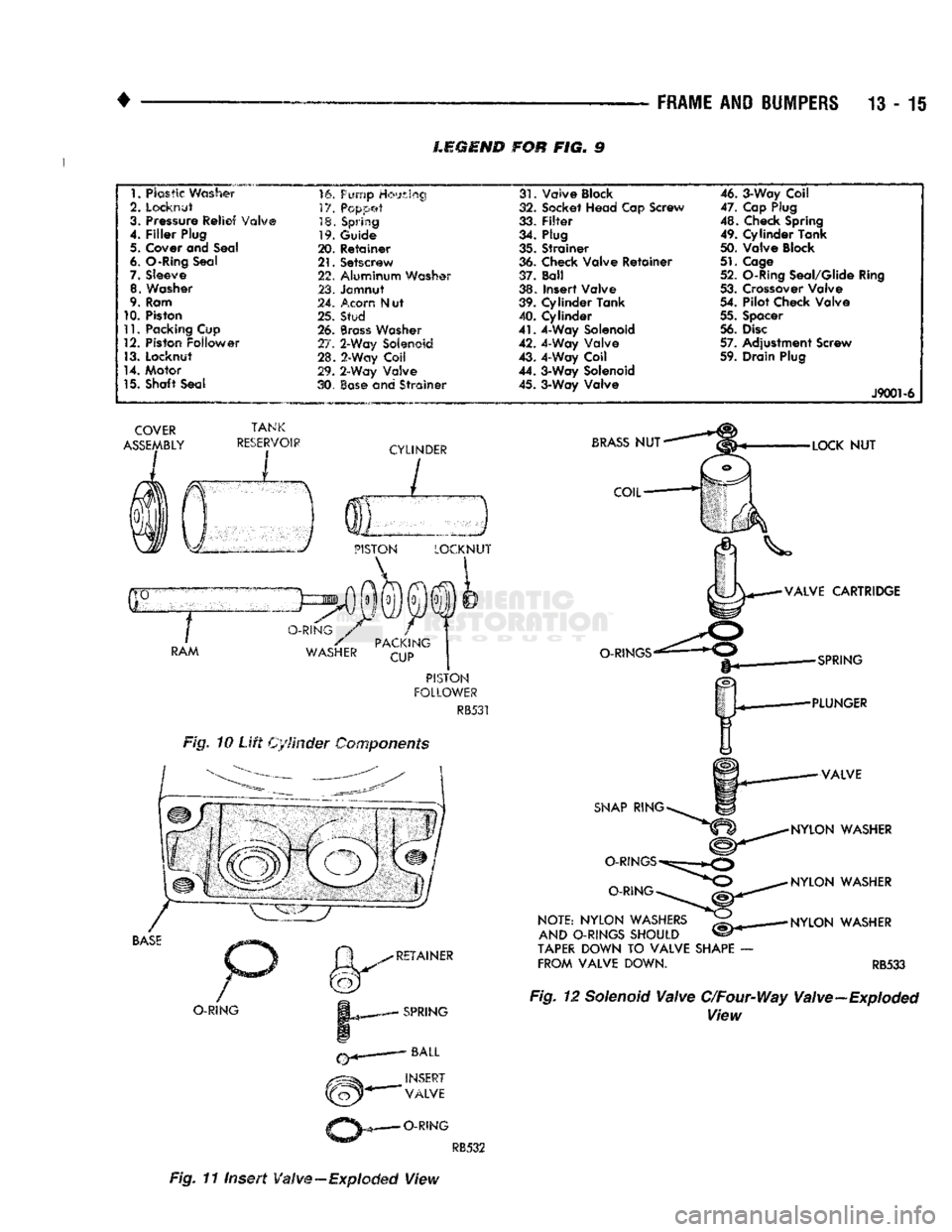
FOR FIG. 9
1.
Plastic
Washer
2. Locknut
3. Pressure Relief Valve
4.
Filler
Plug
5.
Cover
arid
Seal
6.
O-Rirtg Seal
7. Sleeve 8. Washer
9. Ram
10. Piston
11.
Packing Cup
12. Piston Follower
13. Locknut
14. Motor
15. Shaft Seat If. 'imp Housing
V/. pcppet
18. Spring
19. Guide
20. Retainer
21.
Setscrew
22. Aluminum Washer
23. Jamnut
24. Acorn N ut
25. Stud
26.
Brass
Washer
27. 2-Way Solenoid
28. 2-Way Coil
29. 2-Way Valve
30.
Ease
and Strainer
COVER
ASSEMBLY
TANK
RESERVOIR
CYLINDER
I
3
PISTON
LOCKNUT
I i
O-RING
RAM
S
PACKINC
WASHER
CUP
PISTON
FOLLOWER
RB531
Fig. 10
Lift
Cylinder Components
BASE
O-RING
RETAINER
SPRING
NSERT
VALVE
O-RING
31.
Valve Block
32. Socket Head Cap Screw
33.
Filter
34. Plug
35. Strainer
36. Check Valve Retainer
37. Ball
38. Insert Valve
39. Cylinder Tank
40. Cylinder
41.
4-Way Solenoid
42. 4-Way Valve
43. 4-Way Coil
44. 3-Way Solenoid 45. 3-Way Valve 46. 3-Way Coil
47. Cap Plug
48. Check Spring
49. Cylinder Tank
50. Valve Block
51.
Cage
52. O-Ring Seal/Glide Ring
53. Crossover Valve
54. Pilot Check Valve
55. Spacer
56.
Disc
57. Adjustment Screw
59. Drain Plug
J9001-6
BRASS
NUT
COIL
O-RINGS
SNAP
RING
O-RINGS
O-RING
NOTE:
NYLON
WASHERS
AND
O-RINGS
SHOULD
TAPER
DOWN TO
VALVE
SHAPE
FROM
VALVE
DOWN.
LOCK
NUT
VALVE
CARTRIDGE
SPRING
PLUNGER
VALVE
NYLON
WASHER
NYLON
WASHER
NYLON
WASHER
RB533 Fig. 12 Solenoid
Valve
C/Four-Way Valve-Exploded
View
RB532
Fig. 11 Insert
Valve
—Exploded
View
Page 803 of 1502
13
- 16
FRAME
AND
iUMPERS
•
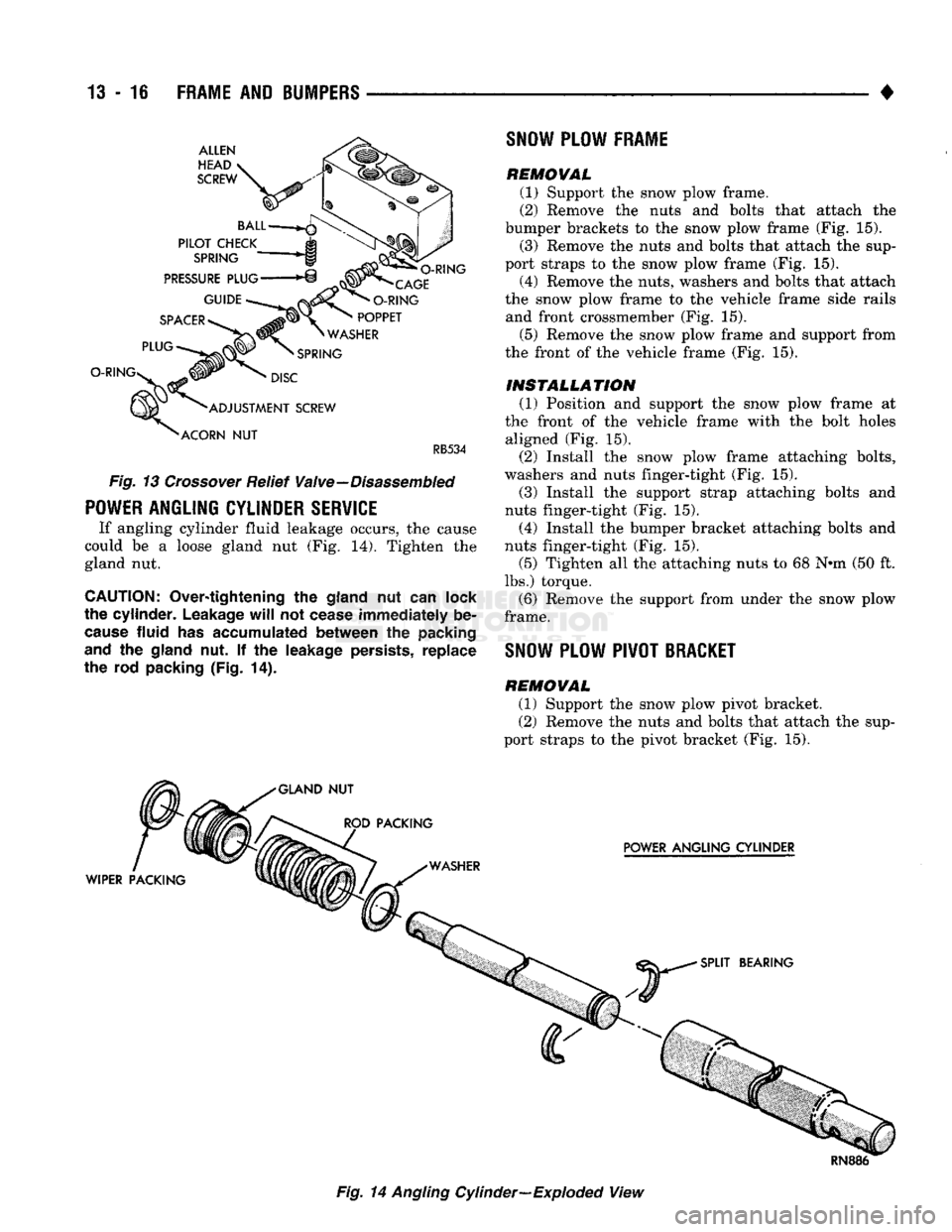
RB534
Fig.
13
Crossover Relief Valve—Disassembled
POWER
ANGLING CYLINDER
SERVICE
If angling cylinder fluid leakage occurs,
the
cause
could
be a
loose gland
nut (Fig. 14).
Tighten
the
gland
nut.
CAUTION:
Over-tightening
the
gland
nut can
lock
the cylinder.
Leakage
will not
cease immediately
be
cause
fluid
has
accumulated between
the
packing
and
the
gland
nut. If the
leakage
persists,
replace
the rod
packing
(Fig.
14),
SNOW
PLOW
FRAME
REMOVAL
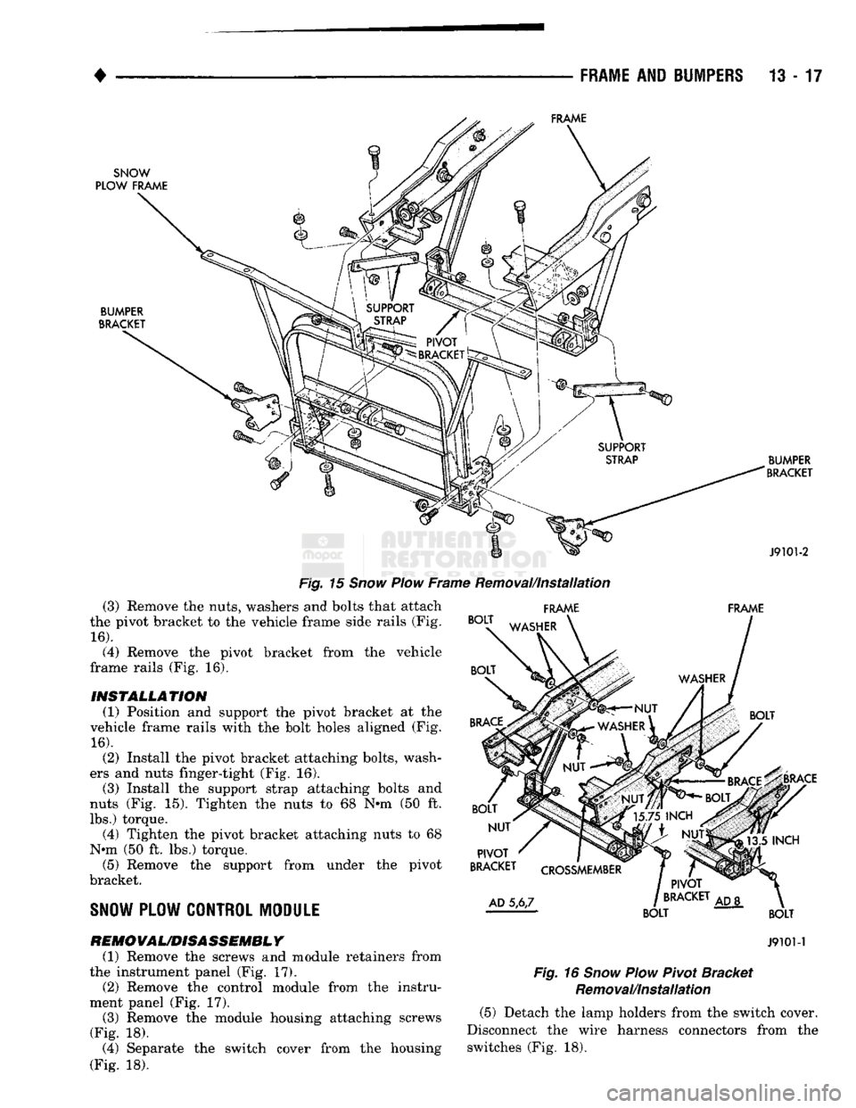
(1) Support
the
snow plow frame.
(2) Eemove
the
nuts
and
bolts that attach
the
bumper brackets
to the
snow plow frame
(Fig. 15).
(3) Remove
the
nuts
and
bolts that attach
the
sup
port straps
to the
snow plow frame
(Fig. 15).
(4) Remove
the
nuts, washers
and
bolts that attach
the snow plow frame
to the
vehicle frame side rails and front crossmember
(Fig. 15).
(5) Remove
the
snow plow frame
and
support from
the front
of the
vehicle frame
(Fig. 15).
INSTALLATION
(1) Position
and
support
the
snow plow frame
at
the front
of the
vehicle frame with
the
bolt holes aligned
(Fig. 15).
(2) Install
the
snow plow frame attaching bolts,
washers
and
nuts finger-tight
(Fig. 15).
(3) Install
the
support strap attaching bolts
and
nuts finger-tight
(Fig. 15).
(4) Install
the
bumper bracket attaching bolts
and
nuts finger-tight
(Fig. 15).
(5) Tighten
all the
attaching nuts
to 68 N*m (50 ft.
lbs.) torque.
(6) Remove
the
support from under
the
snow plow
frame.
SNOW
PLOW PIVOT BRACKET REMOVAL
(1) Support
the
snow plow pivot bracket. (2) Remove
the
nuts
and
bolts that attach
the
sup
port straps
to the
pivot bracket
(Fig. 15).
Fig. 14 Angling Cylinder—Exploded View
Page 804 of 1502
•
FRAME
AND
BUMPERS
13 - 17
Fig.
15
Snow
Plow
Frame Removal/Installation (3) Remove the nuts, washers and bolts that attach
the pivot bracket to the vehicle frame side rails (Fig.
16).
(4) Remove the pivot bracket from the vehicle
frame rails (Fig. 16).
INSTALLATION
(1) Position and support the pivot bracket at the
vehicle frame rails with the bolt holes aligned (Fig.
16).
(2) Install the pivot bracket attaching bolts, wash
ers and nuts finger-tight (Fig. 16).
(3) Install the support strap attaching bolts and
nuts (Fig. 15). Tighten the nuts to 68 N*m (50 ft.
lbs.) torque. (4) Tighten the pivot bracket attaching nuts to 68
Nrni (50 ft. lbs.) torque. (5) Remove the support from under the pivot
bracket.
SNOW
PLOW CONTROL MODULE FRAME FRAME
REMO
VAUDISASSEMBL
Y
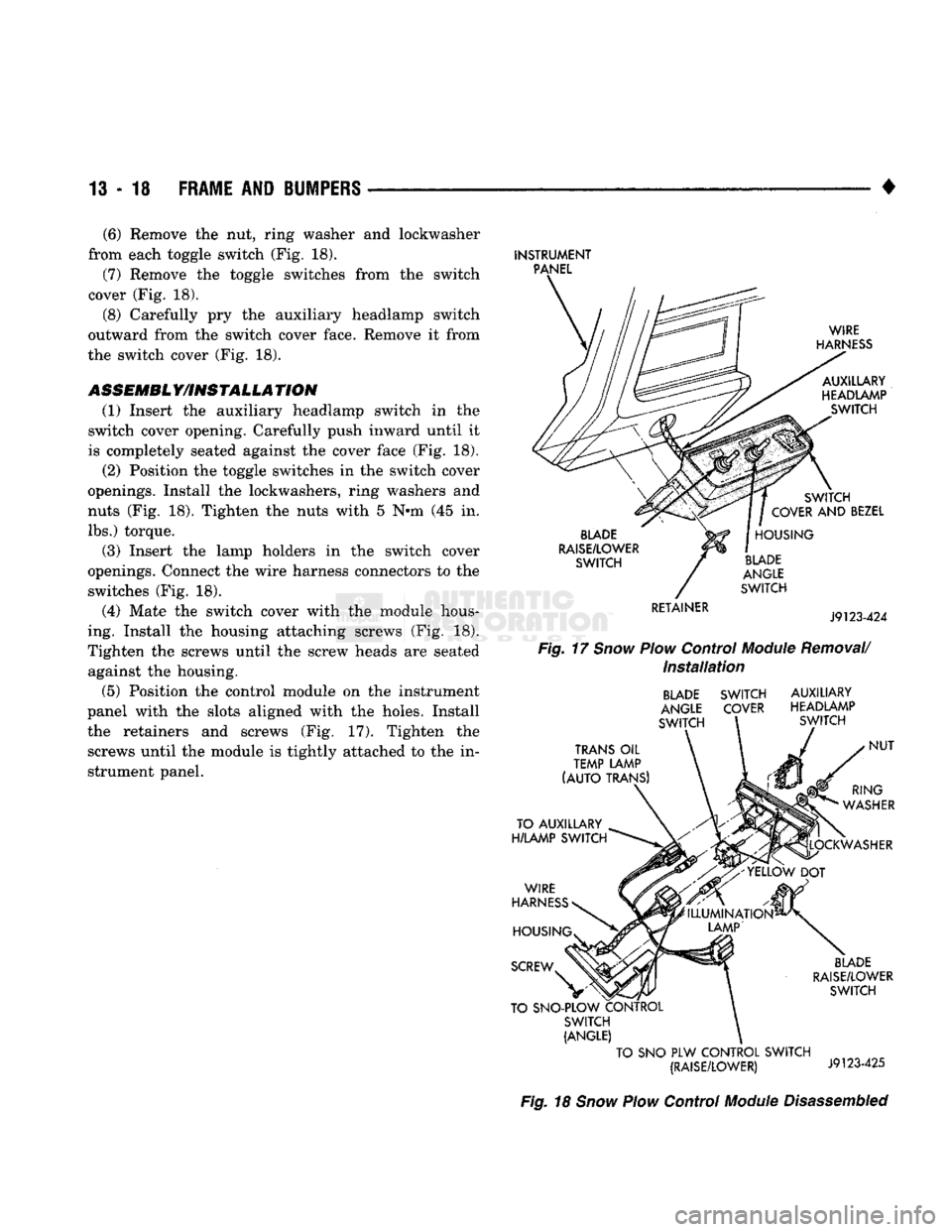
(1) Remove the screws and module retainers from
the instrument panel (Fig. 17).
(2) Remove the control module from the instru
ment panel (Fig. 17).
(3) Remove the module housing attaching screws
(Fig. 18).
(4) Separate the switch cover from the housing
(Fig. 18).
J9101-1
Fig.
16
Snow
Plow
Pivot Bracket Removal/Installation (5) Detach the lamp holders from the switch cover.
Disconnect the wire harness connectors from the switches (Fig. 18).
Page 805 of 1502
13 - 18
FRAME
AND
BUMPERS
(6) Remove the nut, ring washer and loekwasher
from each toggle switch (Fig. 18).
(7) Remove the toggle switches from the switch
cover (Fig. 18).
(8) Carefully pry the auxiliary headlamp switch
outward from the switch cover face. Remove it from
the switch cover (Fig. 18).
ASSEMBL Y/INSTALLA TION (1) Insert the auxiliary headlamp switch in the
switch cover opening. Carefully push inward until it
is completely seated against the cover face (Fig. 18).
(2) Position the toggle switches in the switch cover
openings. Install the lockwashers, ring washers and
nuts (Fig. 18). Tighten the nuts with 5 Nnn (45 in. lbs.) torque.
(3) Insert the lamp holders in the switch cover
openings. Connect the wire harness connectors to the switches (Fig. 18).
(4) Mate the switch cover with the module hous
ing. Install the housing attaching screws (Fig. 18).
Tighten the screws until the screw heads are seated against the housing.
(5) Position the control module on the instrument
panel with the slots aligned with the holes. Install the retainers and screws (Fig. 17). Tighten the screws until the module is tightly attached to the in
strument panel.
INSTRUMENT
PANEL
WIRE
HARNESS
AUXILLARY
HEADLAMP SWITCH
BLADE
RAISE/LOWER
SWITCH
RETAINER SWITCH
COVER
AND
BEZEL
HOUSING
BLADE
ANGLE
SWITCH
J9123-424
Fig.
17
Snow
Plow
Control
Module
Removal/
Installation
BLADE
SWITCH
ANGLE
COVER
SWITCH AUXILIARY
HEADLAMP SWITCH
TRANS
OIL
TEMP LAMP
(AUTO
TRANS)
TO AUXILLARY
H/LAMP
SWITCH
WIRE
HARNESS
RING
WASHER
LOCKWASHER
HOUSING
SCREW
NUT
'ILLUMINATION*
LAMP'
BLADE
RAISE/LOWER
SWITCH
TO SNO-PLOW CONTROL SWITCH
(ANGLE)
TO
SNO PLW
CONTROL SWITCH (RAISE/LOWER)
J9123-425
Fig.
18
Snow
Plow
Control
Module
Disassembled
Page 806 of 1502
•
FRAME
AND
BUMPERS
13 - 19
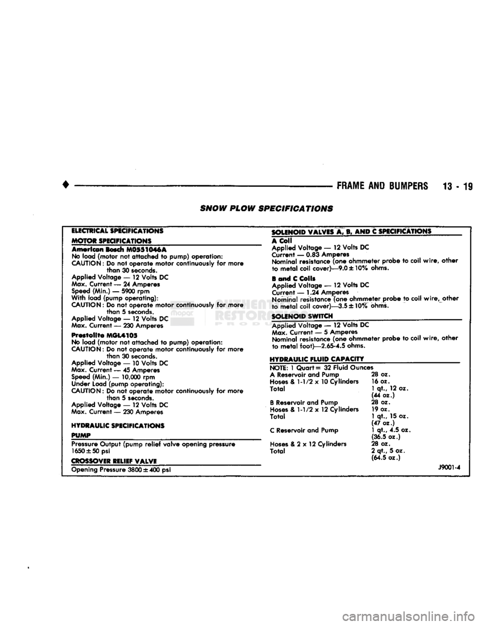
SNOW
PLOW SPECIFICATIONS
ELECTRICAL
SPECIFICATIONS
MOTOR SPECIFICATIONS
American
Bosch M0SS1M6A No
load
(motor
not
attached to pump) operation:
CAUTION:
Do not
operate
motor
continuously
for
more
than
30
seconds.
Applied Voltage
— 12
Volts
DC
Max. Current — 24
Amperes Speed
(Min.) —
5900
rpm
With
load
(pump operating):
CAUTION:
Do
not
operate motor
continuously
for more than 5
seconds.
Applied Voltage — 12 Volts DC
Max.
Current — 230 Amperes
Prestolite MGL4105
No
load (motor not attached to pump) operation:
CAUTION:
Do not operate motor continuously for more than 30
seconds.
Applied Voltage — 10 Volts DC
Max.
Current — 45 Amperes
Speed
(Min.) —
10,000
rpm Under Load (pump operating):
CAUTION:
Do not operate motor continuously for more than 5
seconds.
Applied Voltage —- 12 Volts DC
Max.
Current — 230 Amperes
HYDRAULIC SPECIFICATIONS
PUMP
m
Pressure
Output (pump
relief
valve opening pressure 1650 ±50 psi
CROSSOVER
RELIEF VALVE SOLENOID VALVES
A. B, AND C
SPECIFICATIONS
A
Coll
Applied Voltage — 12 Volts DC Current — 0.83 Amperes Nominal resistance (one ohmmeter probe to coil
wire,
other
to
metal
coil cover)—9.0 ± 10%
ohms.
i and C
Colls
Applied Voltage — 12 Volts DC Current — 1.24 Amperes
Nominal resistance (one ohmmeter probe to coil
wire,
other
to metaT coil cover)—-3.5 ± 10%
ohms.
SOLENOID SWITCH
Applied Voltage — 12 Volts
DC Max.
Current — 5 Amperes Nominal resistance (one ohmmeter probe to coil
wire,
other
to
metal
foot)—2.65-4.5
ohms.
HYDRAULIC
FLUID
CAPACITY NOTE:
1 Quart = 32 Fluid Ounces
A
Reservoir and Pump
Hoses
& 1-1/2 x 10 Cylinders
Total
B
Reservoir and Pump
Hoses
& 1-1/2 x 12 Cylinders
Total
C
Reservoir and Pump
Hoses
& 2 x 12 Cylinders
Total
28 oz.
16 oz.
1
qt., 12 oz.
(44 oz.)
28 oz. 19 oz.
1
qt., 15 oz.
(47 oz.) 1 qt., 4.5 oz.
(36.5 oz.)
28 oz.
2 qt., 5 oz. (64.5 oz.) Opening Pressure
3800
± 400 psi
J9001-4
Page 807 of 1502
13
- 20 FRAME AND IUMPERS
• FRAME
INDEX
page
Frame
Inspection/Measurements 25
Frame
Repair 29 General
Information
page
. . 20
GENERAL INFORMATION
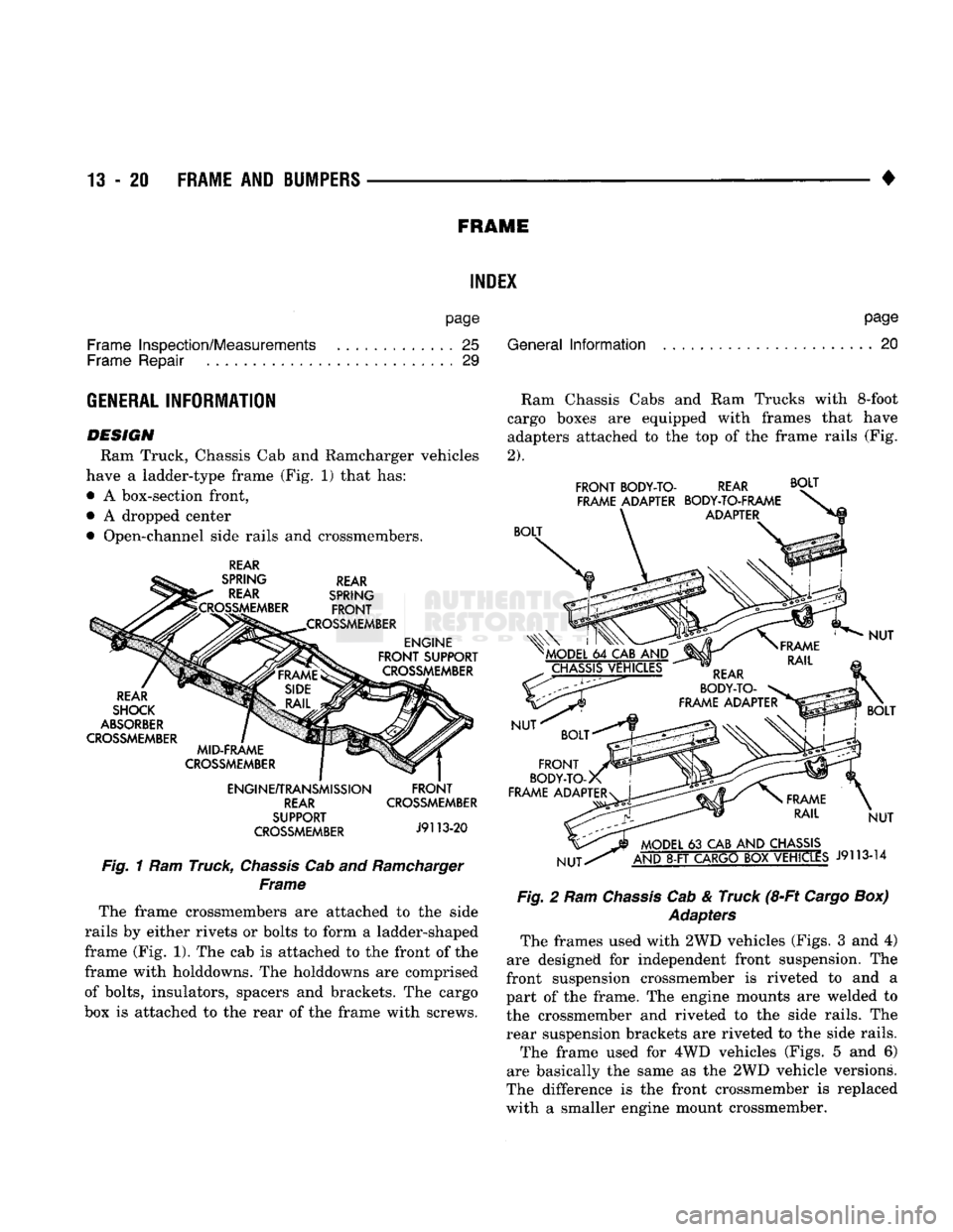
DESIGN
Ram Truck, Chassis Cab and Ramcharger vehicles
have a ladder-type frame (Fig. 1) that has:
• A box-section front,
• A dropped center
• Open-channel side rails and crossmembers.
REAR
SPRING REAR REAR SPRING
^CROSSMEMBER
FRONT
.CROSSMEMBER ENGINE
FRONT
SUPPORT CROSSMEMBER
REAR
SHOCK
ABSORBER
CROSSMEMBER MID-FRAME
CROSSMEMBER
ENGINE/TRANSMISSION REAR
SUPPORT
CROSSMEMBER
FRONT
CROSSMEMBER
J9113-20
Fig.
1 Ram Truck,
Chassis
Cab and
Ramcharger
Frame
The frame crossmembers are attached to the side
rails by either rivets or bolts to form a ladder-shaped
frame (Fig. 1). The cab is attached to the front of the
frame with holddowns. The holddowns are comprised
of bolts, insulators, spacers and brackets. The cargo
box is attached to the rear of the frame with screws. Ram Chassis Cabs and Ram Trucks with
8-foot
cargo boxes are equipped with frames that have
adapters attached to the top of the frame rails (Fig.
2).
FRONT
BODY-TO-
FRAME ADAPTER REAR
BODY-TO-FRAME
ADAPTER
BOLT
BOLT
>
KAC MODEL
64
CAB
AND
CHASSIS VEHICLES
NUT REAR
BODY-TO-
FRAME ADAPTER
BOLT
FRONT
BODY-TO-x
FRAME ADAPTER
NUT NUT
BOLT
NUT
MODEL
63
CAB
AND
CHASSIS
AND
8-FT
CARGO
BOX
VEHICLES
J9113-14
Fig.
2 Ram
Chassis
Cab & Truck (8-Ft
Cargo
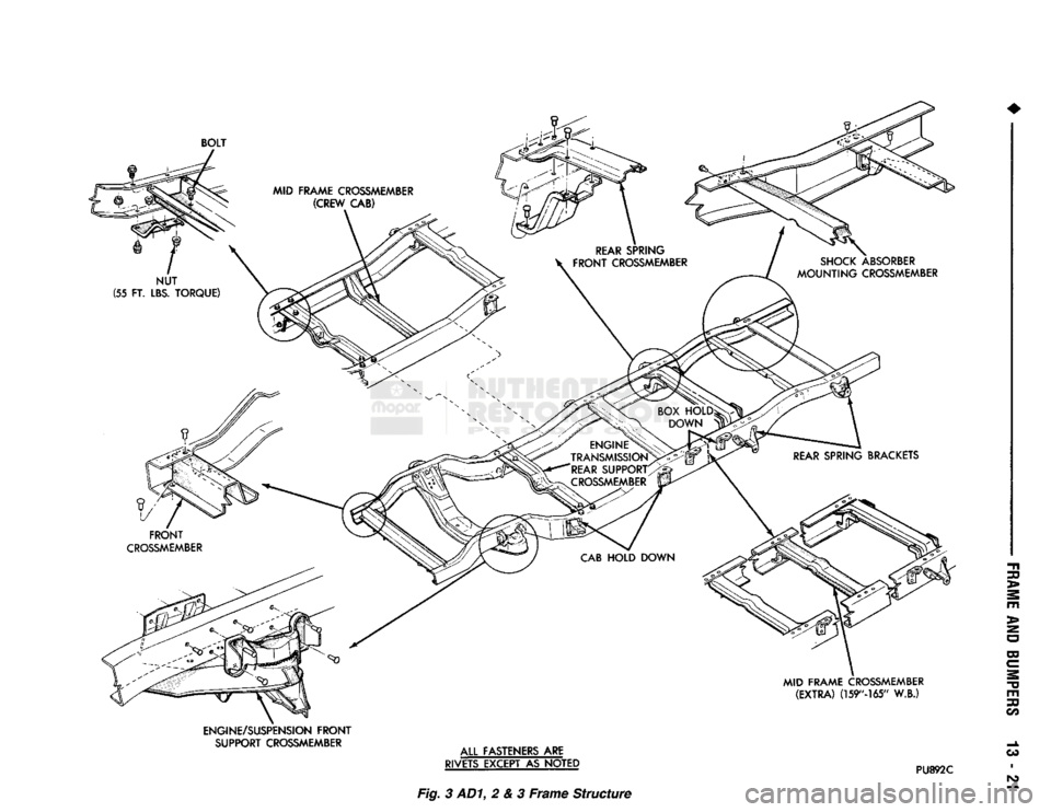
Box) Adapters The frames used with
2WD
vehicles (Figs. 3 and 4)
are designed for independent front suspension. The
front suspension crossmember is riveted to and a
part of the frame. The engine mounts are welded to
the crossmember and riveted to the side rails. The
rear suspension brackets are riveted to the side rails.
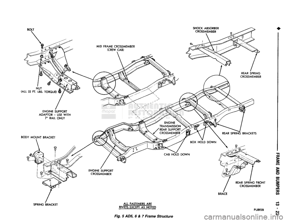
The frame used for 4WD vehicles (Figs. 5 and 6)
are basically the same as the
2WD
vehicle versions.
The difference is the front crossmember is replaced
with a smaller engine mount crossmember.
Page 808 of 1502
MID FRAME CROSSMEMBER
(EXTRA)
(159"-165"
W.B.)
ENGINE/SUSPENSION FRONT SUPPORT CROSSMEMBER
ALL
FASTENERS ARE
RIVETS EXCEPT AS NOTED
PU892C
30
>
O
m
30
OS I Fig.
3 AD1, 2 & 3 Frame Structure
Page 809 of 1502
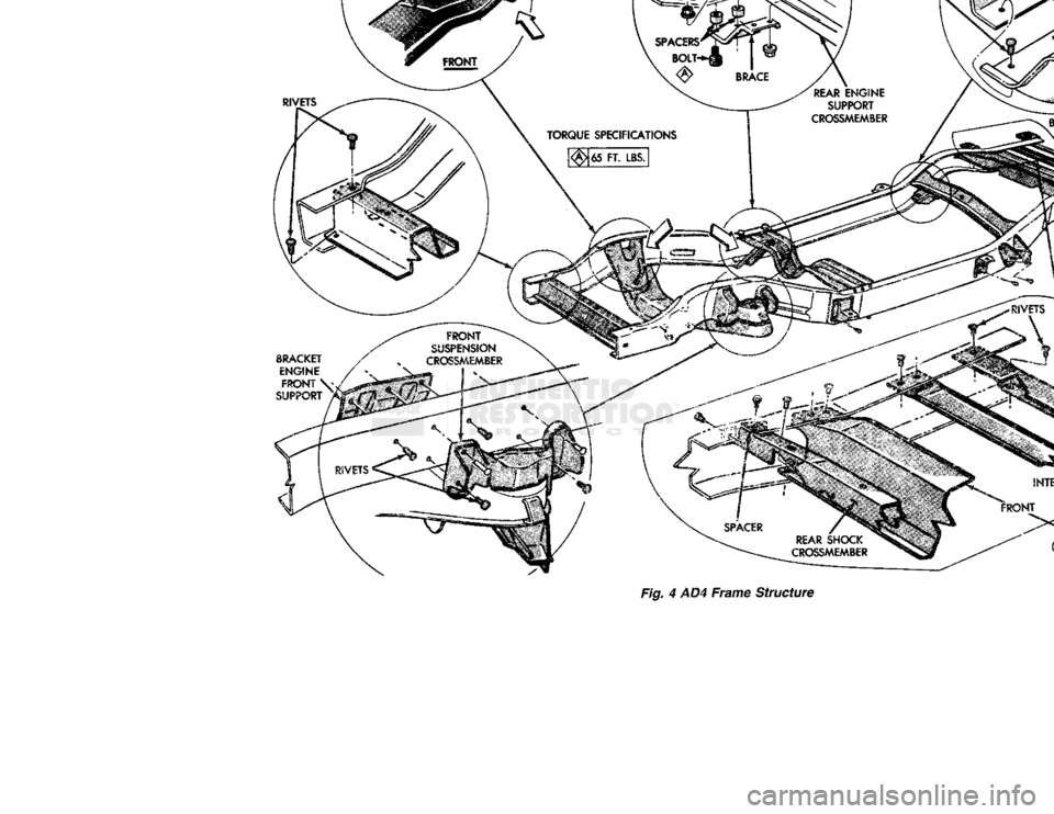
Fig. 4 AD4 Frame Structure
Page 810 of 1502
RIVETS EXCEPT AS NOTED
PU893B
Fig.
5
ADS,
6 & 7 Frame Structure