DODGE TRUCK 1993 Service Repair Manual
Manufacturer: DODGE, Model Year: 1993, Model line: TRUCK, Model: DODGE TRUCK 1993Pages: 1502, PDF Size: 80.97 MB
Page 771 of 1502
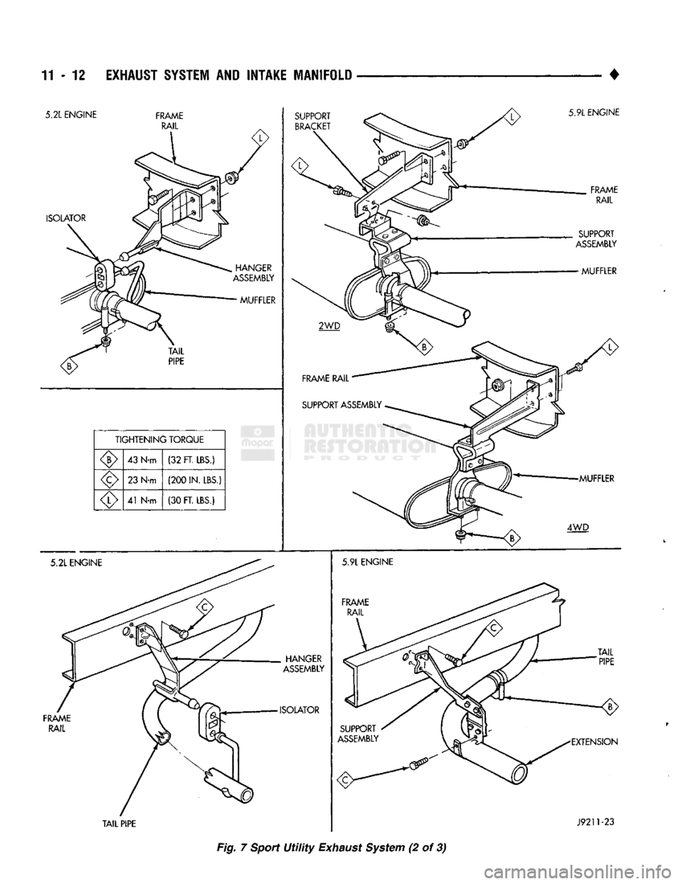
11-12 EXHAUST SYSTEM AND INTAKE MANIFOLD
•
Fig. 7
Sport
Utility
Exhaust
System (2 of 3)
Page 772 of 1502
•
EXHAUST SYSTEM
AND
INTAKE MANIFOLD
11-13
TIGHTENING
TORQUE
23
N-m
(200
IN. LBS.)
7
N-m
(65
IN. LBS.)
5 N-m
(40
IN. LBS.)
HEAT
SHIELD CATALYTIC
CONVERTER
LOWER HEAT SHIELD HEAT
SHIELD UPPER
HEAT
SHIELD
CROSSMEMBER
SKID
PLATE
UPPER HEAT SHIELD
(6 IN.
RAIL) CONED WASHER
UPPER HEAT SHIELD
(7 IN.
RAIL)
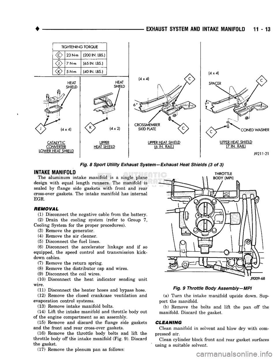
J9211-21
Fig.
8
Sport
Utility
Exhaust
System—Exhaust
Heat
Shields
(3 of 3)
INTAKE MANIFOLD
The aluminum intake manifold is a single plane
design with equal length runners. The manifold is sealed by flange side gaskets with front and rear
cross-over gaskets. The intake manifold has internal
EGR.
REMOVAL
(1) Disconnect the negative cable from the battery.
(2) Drain the cooling system (refer to Group 7,
Cooling System for the proper procedures).
(3) Remove the generator.
(4) Remove the air cleaner.
(5) Disconnect the fuel lines.
(6) Disconnect the accelerator linkage and if so
equipped, the speed control and transmission kick-
down cables.
(7) Remove the return spring.
(8) Remove the distributor cap and wires.
(9) Disconnect the coil wires.
(10) Disconnect the heat indicator sending unit
wire.
(11) Disconnect the heater hoses and bypass hose.
(12) Remove the closed crankcase ventilation and
evaporation control systems. (13) Remove intake manifold bolts.
(14) Lift the intake manifold and throttle body out
of the engine compartment as an assembly. (15) Remove and discard the flange side gaskets
and the front and rear cross-over gaskets.
(16) Remove the throttle body bolts and lift the
throttle body off the intake manifold (Fig. 9). Discard
the gasket. (17) Remove the plenum pan as follows:
THROTTLE
BODY
(MPI)
J9209-68
Fig.
9
Throttle
Body Assembly—MPI
(a) Turn the intake manifold upside down. Sup
port the manifold.
(b) Remove the bolts and lift the pan off the
manifold. Discard the gasket.
CLEANING
Clean manifold in solvent and blow dry with com
pressed air.
Clean cylinder block front and rear gasket surfaces
using a suitable solvent.
Page 773 of 1502
11-14
EXHAUST
SYSTEM
AND
INTAKE
MANIFOLD
• The plenum pan rail must be clean and dry (free of
all foreign material).
INSPECTION
Inspect manifold for cracks.
Inspect mating surfaces of manifold for flatness
with a straightedge.
INSTALLATION
(1) Install the plenum pan, if removed, as follows: (a) Turn the intake manifold upside down. Sup
port the manifold.
(b) Place a new plenum pan gasket onto the seal
rail of the intake manifold. Position the pan over
the gasket. Align all the gasket and pan holes with
the intake manifold. (c) Hand start all bolts.
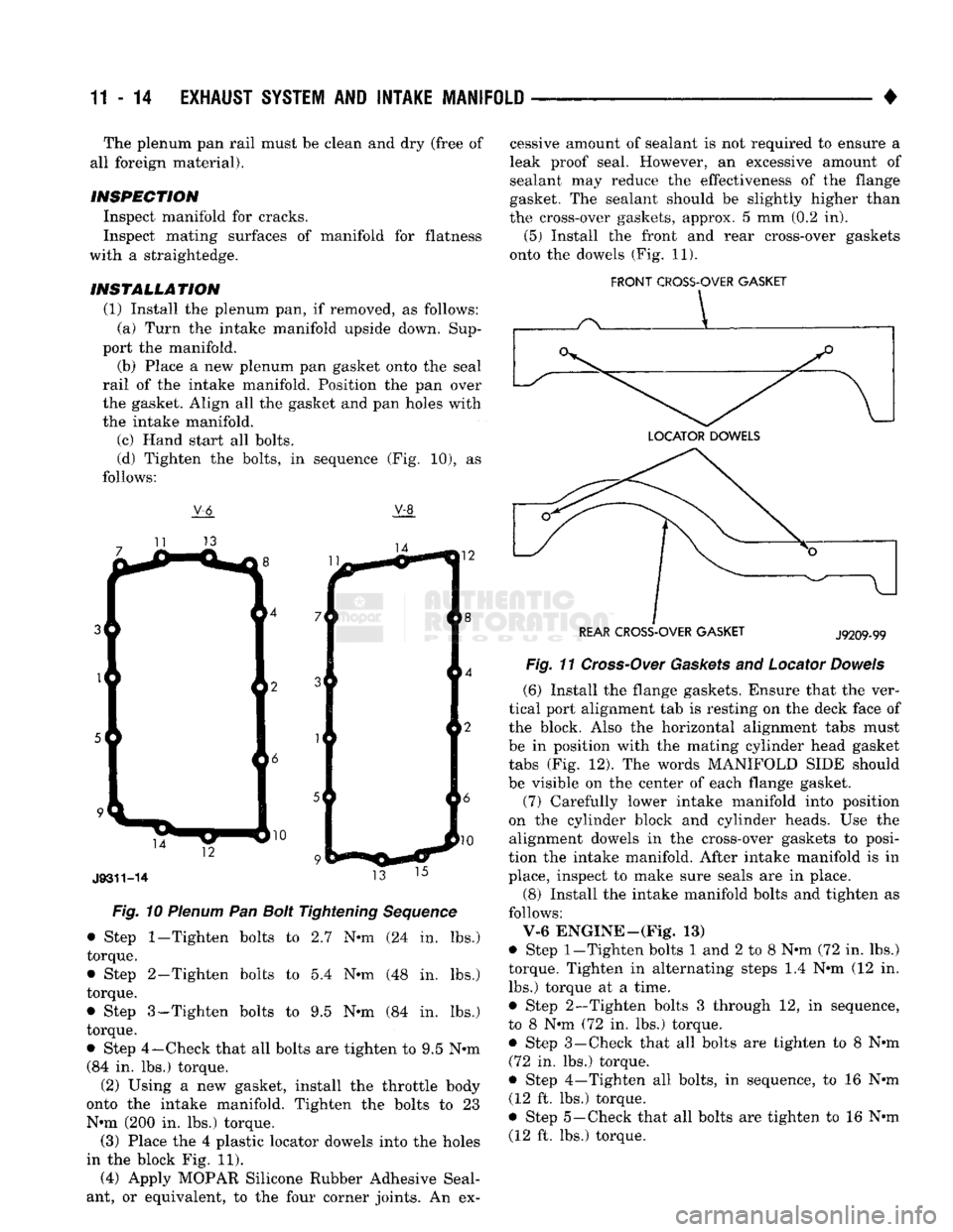
(d) Tighten the bolts, in sequence (Fig. 10), as
follows:
V-6
V-8
Fig.
10
Plenum
Pan
Bolt
Tightening
Sequence
• Step
1-Tighten
bolts to 2.7 N*m (24 in. lbs.)
torque.
• Step 2-Tighten bolts to 5.4 N«m (48 in. lbs.)
torque.
• Step 3-Tighten bolts to 9.5 Nnn (84 in. lbs.)
torque.
• Step 4—Check that all bolts are tighten to 9.5 N®m (84 in. lbs.) torque.
(2) Using a new gasket, install the throttle body
onto the intake manifold. Tighten the bolts to 23
Nun (200 in. lbs.) torque. (3) Place the 4 plastic locator dowels into the holes
in the block Fig. 11).
(4) Apply MOPAR Silicone Rubber Adhesive Seal
ant, or equivalent, to the four corner joints. An ex cessive amount of sealant is not required to ensure a
leak proof seal. However, an excessive amount of
sealant may reduce the effectiveness of the flange
gasket. The sealant should be slightly higher than
the cross-over gaskets, approx. 5 mm (0.2 in).
(5) Install the front and rear cross-over gaskets
onto the dowels (Fig. 11).
FRONT
CROSS-OVER
GASKET
REAR
CROSS-OVER
GASKET
J9209-99
Fig
11
Cross-Over
Gaskets
and Locator
Dowels
(6) Install the flange gaskets. Ensure that the ver
tical port alignment tab is resting on the deck face of
the block. Also the horizontal alignment tabs must
be in position with the mating cylinder head gasket
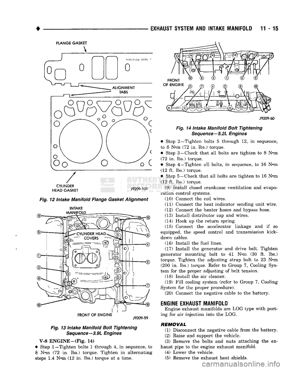
tabs (Fig. 12). The words MANIFOLD SIDE should
be visible on the center of each flange gasket.
(7) Carefully lower intake manifold into position
on the cylinder block and cylinder heads. Use the alignment dowels in the cross-over gaskets to posi
tion the intake manifold. After intake manifold is in
place, inspect to make sure seals are in place.
(8) Install the intake manifold bolts and tighten as
follows:
V-6 ENGINE—(Fig. 13)
• Step
1-Tighten
bolts 1 and 2 to 8 Nun (72 in. lbs.)
torque. Tighten in alternating steps 1.4 Nun (12 in. lbs.) torque at a time.
• Step 2—Tighten bolts 3 through 12, in sequence,
to 8 Nun (72 in. lbs.) torque.
• Step 3—Check that all bolts are tighten to 8 Nun (72 in. lbs.) torque.
• Step 4—Tighten all bolts, in sequence, to 16 Nun (12 ft. lbs.) torque.
• Step 5—Check that all bolts are tighten to 16 Nun (12 ft. lbs.) torque.
Page 774 of 1502
EXHAUST SYSTEM
AND
INTAKE MANIFOLD
11-15
FLANGE GASKET
o
o
CYLINDER
HEAD GASKET
J9209-101
Fig. 12 Intake Manifold Flange Gasket Alignment
®— INTAKE
MANIFOLD
FRONT OF
ENGINE
J9209-59
Fig. 13 Intake Manifold Bolt Tightening Sequence—3.9L Engines
V-8 ENGINE—(Fig* 14)
• Step
1—Tighten
bolts 1 through 4, in sequence, to 8 Nun (72 in. lbs.) torque. Tighten in alternating
steps 1.4 Nun (12 in. lbs.) torque at a time.
FRONT
OF ENGINE
J9209-60
Fig. 14 Intake Manifold Bolt Tightening Sequence—5.2L Engines
• Step 2—Tighten bolts 5 through 12, in sequence,
to 8 Nun (72 in. lbs.) torque. • Step 3—Check that all bolts are tighten to 8 Nun (72 in. lbs.) torque.
• Step 4—Tighten all bolts, in sequence, to 16 Nun (12 ft. lbs.) torque.
• Step 5—Check that all bolts are tighten to 16 Nun (12 ft. lbs.) torque.
(9) Install closed crankcase ventilation and evapo
ration control systems. (10) Connect the coil wires.
(11) Connect the heat indicator sending unit wire.
(12) Connect the heater hoses and bypass hose.
(13) Install distributor cap and wires.
(14) Hook up the return spring.
(15) Connect the accelerator linkage and if so
equipped, the speed control and transmission kick-
down cables. (16) Install the fuel lines,
(17) Install the generator and drive belt. Tighten
generator mounting bolt to 41 Nun (30 ft. lbs.)
torque. Tighten the adjusting strap bolt to 23 Nun (200 in. lbs.) torque. Refer to Group 7, Cooling Sys
tem for the proper adjusting of belt tension. (18) Install the air cleaner. (19) Fill cooling system (refer to Group 7, Cooling
System for the proper procedure). (20) Connect the negative cable to the battery.
ENGINE EXHAUST MANIFOLD
Engine exhaust manifolds are LOG type with port
ing for air injection into the LOG.
REMOVAL (1) Disconnect the negative cable from the battery.
(2) Raise and support the vehicle.
(3) Remove the bolts and nuts attaching the ex
haust pipe to the engine exhaust manifold. (4) Lower the vehicle. (5) Remove the exhaust heat shields.
Page 775 of 1502
11-16
EXHAUST
SYSTEM
AND
INTAKE
MANIFOLD
• (6) Remove bolts, nuts and washers attaching
manifold to cylinder head. (7) Remove manifold from the cylinder head.
CLEANING Clean mating surfaces on cylinder head and mani
fold. Wash with solvent and blow dry with com
pressed air.
INSPECTION Inspect manifold for cracks.
Inspect mating surfaces of manifold for flatness
with a straight edge. Gasket surfaces must be flat
within 0.2 mm per 300 mm (0.008 inch per foot).
INSTALLATION
CAUTION:
If the studs came out
with
the nuts when removing the engine exhaust
manifold,
install
new
studs.
Apply sealer on the coarse
thread
ends.
Wa
ter leaks may develop at the studs if
this
precaution
is
not taken.
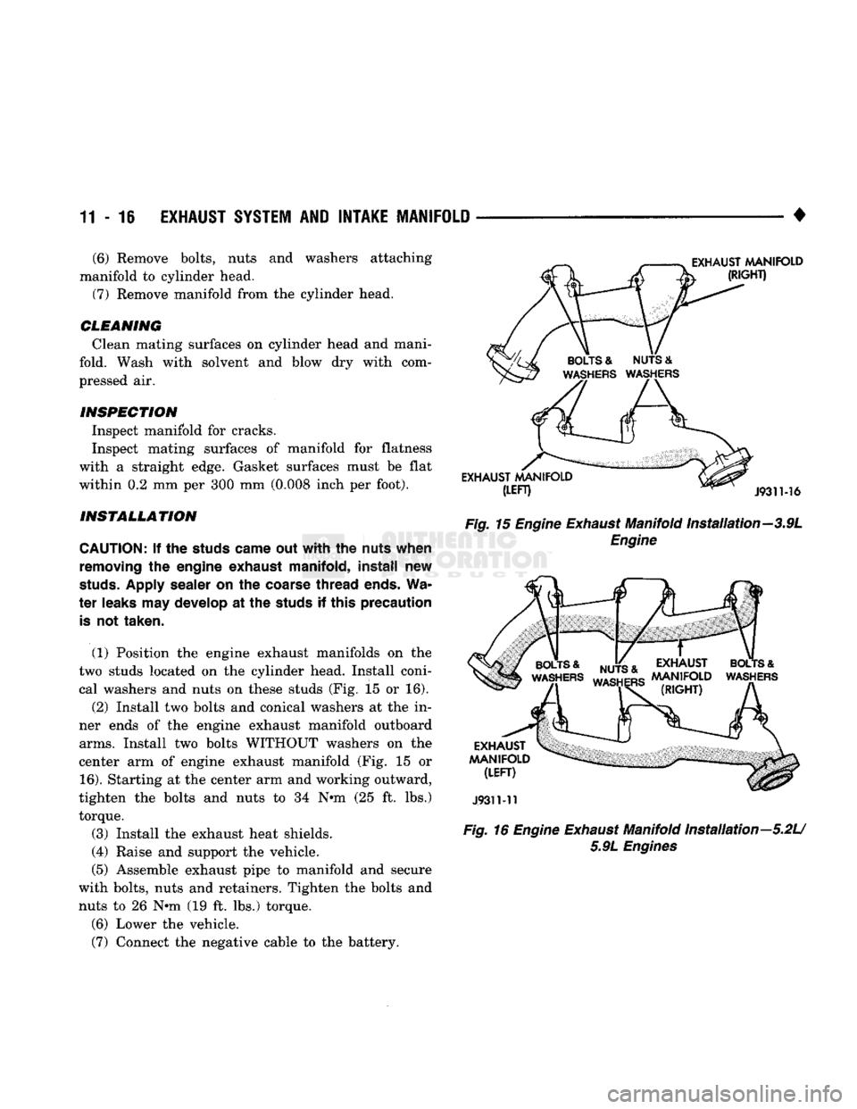
(1) Position the engine exhaust manifolds on the
two studs located on the cylinder head. Install coni cal washers and nuts on these studs (Fig. 15 or 16). (2) Install two bolts and conical washers at the in
ner ends of the engine exhaust manifold outboard
arms.
Install two bolts WITHOUT washers on the
center arm of engine exhaust manifold (Fig. 15 or
16).
Starting at the center arm and working outward,
tighten the bolts and nuts to 34
Nth
(25 ft. lbs.) torque.
(3) Install the exhaust heat shields.
(4) Raise and support the vehicle.
(5) Assemble exhaust pipe to manifold and secure
with bolts, nuts and retainers. Tighten the bolts and nuts to 26
N-m
(19 ft. lbs.) torque.
(6) Lower the vehicle.
(7) Connect the negative cable to the battery.
Fig.
15
Engine
Exhaust
Manifold Installation—3.9L
Engine
J9311-11
Fig.
16
Engine
Exhaust
Manifold Installation—5.2U 5.9L
Engines
Page 776 of 1502
•
EXHAUST SYSTEM AND INTAKE MANIFOLD 11 - 17 8ERY1CE PROCEDURES
(DIESEL ENGINES)
INDEX
page
Charge
Air
Cooler
(Intercooler)
25
Engine
Exhaust
Manifold
18
Exhaust
Pipe
17
Exhaust
Tailpipe
18
EXHAUST PIPE
REMOVAL
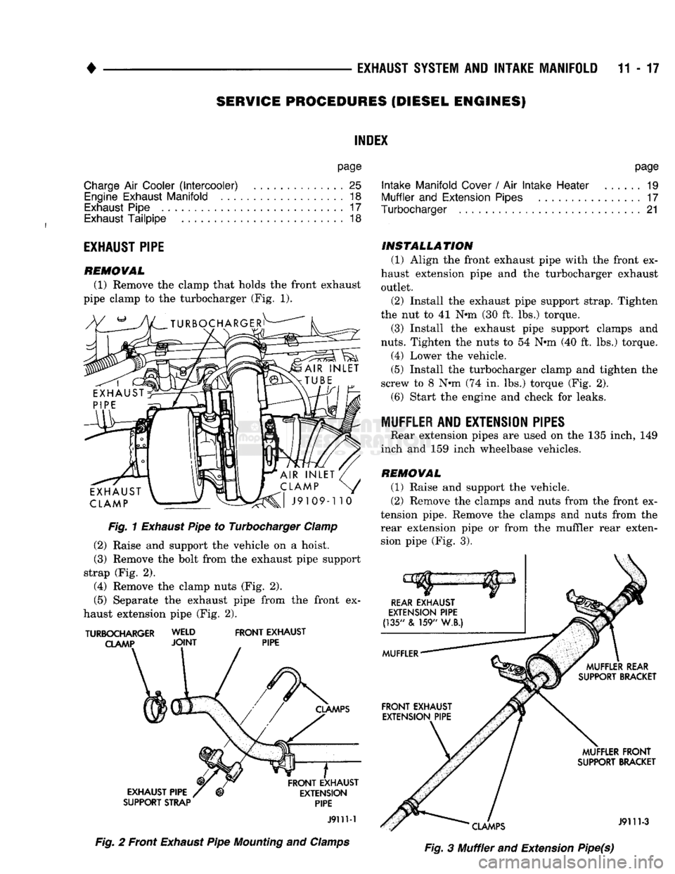
(1) Remove the clamp that holds the front exhaust
pipe clamp to the turbocharger (Fig. 1).
Fig.
1
Exhaust
Pipe to Turbocharger
Clamp
(2)
Raise and support the vehicle on a hoist.
(3)
Remove the bolt from the exhaust pipe support
strap (Fig. 2).
(4)
Remove the clamp nuts (Fig. 2).
(5)
Separate the exhaust pipe from the front ex
haust extension pipe (Fig. 2).
TURBOCHARGER WELD
FRONT
EXHAUST
CLAMP
JOINT
PIPE
SUPPORT STRAP
PIPE
J911M
Fig.
2 Front
Exhaust
Pipe
Mounting
and
Clamps
page
Intake
Manifold
Cover
/ Air
Intake
Heater
19
Muffler
and
Extension
Pipes
17
Turbocharger
21
INSTALLATION
(1)
Align the front exhaust pipe with the front ex
haust extension pipe and the turbocharger exhaust outlet.
(2)
Install the exhaust pipe support strap. Tighten
the nut to 41 Nun (30 ft. lbs.) torque.
(3)
Install the exhaust pipe support clamps and
nuts.
Tighten the nuts to 54 Nun (40 ft. lbs.) torque.
(4)
Lower the vehicle.
(5)
Install the turbocharger clamp and tighten the
screw to 8 Nun (74 in. lbs.) torque (Fig. 2). (6) Start the engine and check for leaks.
MUFFLER AND EXTENSION PIPES Rear extension pipes are used on the 135 inch, 149
inch and 159 inch wheelbase vehicles.
REMOVAL
(1)
Raise and support the vehicle.
(2)
Remove the clamps and nuts from the front ex
tension pipe. Remove the clamps and nuts from the rear extension pipe or from the muffler rear extension pipe (Fig. 3).
Fig.
3 Muffler and Extension Pipe(s)
Page 777 of 1502
11-18 EXHAUST
SYSTEM
AND
INTAKE MANIFOLD
MUFFLER
REAR
SUPPORT
BRACKET
MUFFLER
FRONT
SUPPORT BRACKET
159"
W.B.)-2
REQUIRED
MUFFLER
INSULATOR
FRAME
RAIL
/
SHOULDER
BOLT
MUFFLER
INSULATOR
MUFFLER
FRONT
SUPPORT BRACKET
(131", 135" & 149" W.B.] 1 REQUIRED
SHOULDER BOLTS
J9211-26
Fig.
4 Muffler Front/Rear
Support
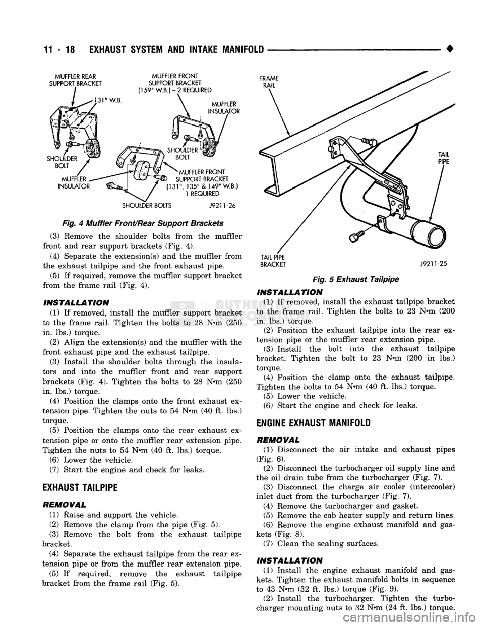
Brackets (3) Remove the shoulder bolts from the muffler
front and rear support brackets (Fig. 4).
(4) Separate the extension(s) and the muffler from
the exhaust tailpipe and the front exhaust pipe.
(5) If required, remove the muffler support bracket
from the frame rail (Fig. 4).
INSTALLATION (1) If removed, install the muffler support bracket
to the frame rail. Tighten the bolts to 28 Nun (250 in. lbs.) torque.
(2) Align the extension(s) and the muffler with the
front exhaust pipe and the exhaust tailpipe.
(3) Install the shoulder bolts through the insula
tors and into the muffler front and rear support
brackets (Fig. 4). Tighten the bolts to 28 N-m (250 in. lbs.) torque.
(4) Position the clamps onto the front exhaust ex
tension pipe. Tighten the nuts to 54 Nun (40 ft. lbs.) torque.
(5) Position the clamps onto the rear exhaust ex
tension pipe or onto the muffler rear extension pipe.
Tighten the nuts to 54 Nun (40 ft. lbs.) torque.
(6) Lower the vehicle. (7) Start the engine and check for leaks.
EXHAUST
TAILPIPE
REMOVAL (1) Raise and support the vehicle.
(2) Remove the clamp from the pipe (Fig. 5).
(3) Remove the bolt from the exhaust tailpipe
bracket. (4) Separate the exhaust tailpipe from the rear ex
tension pipe or from the muffler rear extension pipe. (5) If required, remove the exhaust tailpipe
bracket from the frame rail (Fig. 5).
TAIL
PIPE
BRACKET
J9211-25
Fig.
5
Exhaust
Tailpipe
INSTALLATION
(1) If removed, install the exhaust tailpipe bracket
to the frame rail. Tighten the bolts to 23 Nun (200 in. lbs.) torque. (2) Position the exhaust tailpipe into the rear ex
tension pipe or the muffler rear extension pipe. (3) Install the bolt into the exhaust tailpipe
bracket. Tighten the bolt to 23 Nun (200 in lbs.) torque.
(4) Position the clamp onto the exhaust tailpipe.
Tighten the bolts to 54 Nun (40 ft. lbs.) torque.
(5) Lower the vehicle.
(6) Start the engine and check for leaks.
ENGINE
EXHAUST MANIFOLD
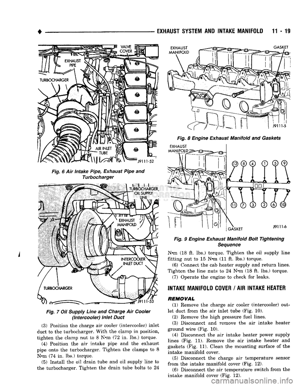
REMOVAL (1) Disconnect the air intake and exhaust pipes
(Fig. 6). (2) Disconnect the turbocharger oil supply line and
the oil drain tube from the turbocharger (Fig. 7). (3) Disconnect the charge air cooler (intercooler)
inlet duct from the turbocharger (Fig. 7). (4) Remove the turbocharger and gasket. (5) Remove the cab heater supply and return lines.
(6) Remove the engine exhaust manifold and gas
kets (Fig. 8). (7) Clean the sealing surfaces.
INSTALLATION (1) Install the engine exhaust manifold and gas
kets.
Tighten the exhaust manifold bolts in sequence
to 43 Nun (32 ft. lbs.) torque (Fig. 9). (2) Install the turbocharger. Tighten the turbo
charger mounting nuts to 32 Nun (24 ft. lbs.) torque.
Page 778 of 1502
EXHAUST SYSTEM AND INTAKE MANIFOLD 11 - 19
EXHAUST
MANIFOLD
GASKET
J9111-52
Fig.
6 Air intake Pipe,
Exhaust
Pipe and
Turbocharger
,
till
TURBOCHARGER,
OIL SUPPLY
UNE
^J9111-53
Fig.
7
OH
Supply Line and Charge Air Cooler (intercooler) inlet
Duct
(3) Position the charge air cooler (intercooler) inlet
duct to the turbocharger. With the clamp in position,
tighten the clamp nut to 8 Nun (72 in. lbs.) torque.
(4) Position the air intake pipe and the exhaust
pipe onto the turbocharger. Tighten the clamps to 8 Nun (74 in. lbs.) torque.
(5) Install the oil drain tube and oil supply line to
the turbocharger. Tighten the drain tube bolts to 24
J9111-5
Fig.
8
Engine
Exhaust
Manifold and
Gaskets
EXHAUST
MANIFOLD^^^^
GASKET
J9111-6
Fig.
9
Engine
Exhaust
Manifold
Bolt
Tightening
Sequence
Nun (18 ft. lbs.) torque. Tighten the oil supply line
fitting nut to 15 Nun (11 ft. lbs.) torque. (6) Connect the cab heater supply and return lines.
Tighten the line nuts to 24 Nun (18 ft. lbs.) torque. (7) Operate the engine to check for leaks.
INTAKE MANIFOLD COVER / AIR INTAKE HEATER
REMOVAL (1) Remove the charge air cooler (intercooler) out
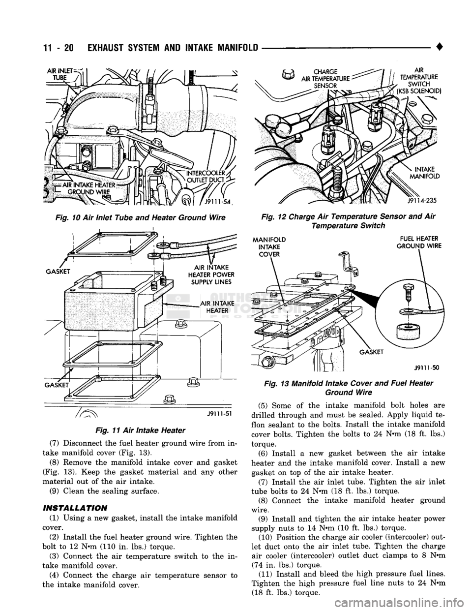
let duct from the air inlet tube (Fig. 10). (2) Remove the high pressure fuel lines. (3) Disconnect and remove the air intake heater
ground wire (Fig. 10). (4) Disconnect the air intake heater power supply
lines (Fig. 11). Remove the air intake heater and
gaskets (Fig. 11). Clean the mounting surface of the
intake manifold cover. (5) Disconnect the charge air temperature sensor
from the intake manifold cover (Fig. 12). (6) Disconnect the air temperature switch from the
intake manifold cover (Fig. 12).
Page 779 of 1502
11-20 EXHAUST
SYSTEM
AND
INTAKE MANIFOLD
AIR INLET
INTERCOOLER/ OUTLET DUCT
X^l
/J9111-54.
Fig.
10 Air Inlet Tube and Heater
Ground
Wire
J9111-51
Fig.
11 Air Intake Heater (7) Disconnect the fuel heater ground wire from in
take manifold cover (Fig. 13).
(8) Remove the manifold intake cover and gasket
(Fig. 13). Keep the gasket material and any other
material out of the air intake.
(9) Clean the sealing surface.
INSTALLATION
(1) Using a new gasket, install the intake manifold
cover. (2) Install the fuel heater ground wire. Tighten the
bolt to 12 Nun (110 in. lbs.) torque.
(3) Connect the air temperature switch to the in
take manifold cover.
(4) Connect the charge air temperature sensor to
the intake manifold cover.
AIR
TEMPERATURE
SWITCH
(KSB
SOLENOID)
J9114-235
Fig.
12
Charge
Air
Temperature
Sensor
and Air
Temperature
Switch
AAANIFOLD INTAKE COVER FUEL HEATER
GROUND WIRE
J9111-50
Fig.
13 Manifold Intake
Cover
and
Fuel
Heater
Ground
Wire
(5) Some of the intake manifold bolt holes are
drilled through and must be sealed. Apply liquid te
flon sealant to the bolts. Install the intake manifold
cover bolts. Tighten the bolts to 24 Nun (18 ft. lbs.)
torque.
(6) Install a new gasket between the air intake
heater and the intake manifold cover. Install a new gasket on top of the air intake heater.
(7) Install the air inlet tube. Tighten the air inlet
tube bolts to 24 Nun (18 ft. lbs.) torque. (8) Connect the intake manifold heater ground
wire.
(9) Install and tighten the air intake heater power
supply nuts to 14 Nun (10 ft. lbs.) torque. (10) Position the charge air cooler (intercooler) out
let duct onto the air inlet tube. Tighten the charge air cooler (intercooler) outlet duct clamps to 8 Nun (74 in. lbs.) torque. (11) Install and bleed the high pressure fuel lines.
Tighten the high pressure fuel line nuts to 24 Nun (18 ft. lbs.) torque.
Page 780 of 1502
•
EXHAUST
SYSTEM
AND
INTAKE
MANIFOLD
11 - 21
TURBOCHARGER
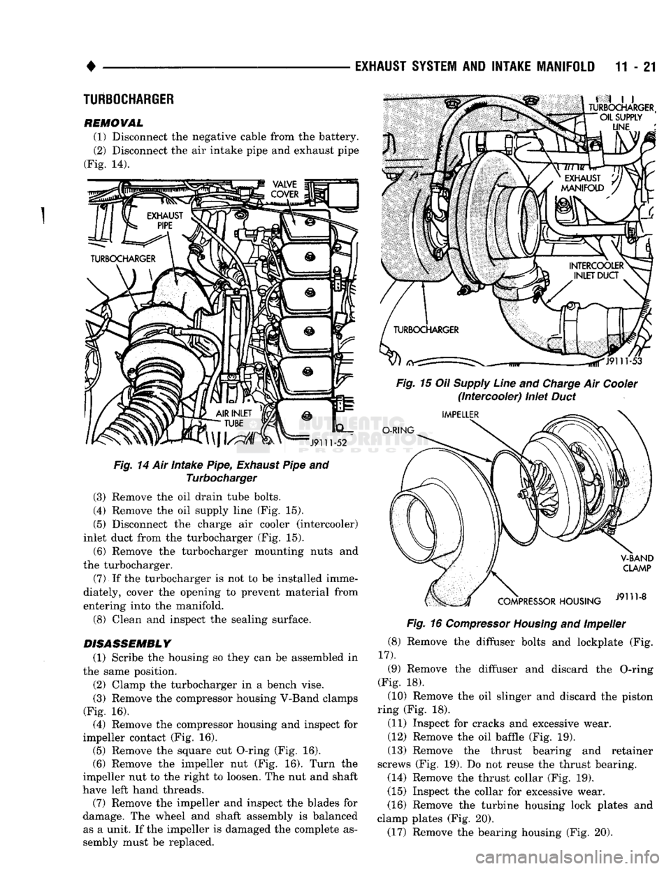
REMOVAL (1) Disconnect the negative cable from the battery. (2) Disconnect the air intake pipe and exhaust pipe
(Fig. 14).
Fig.
14 Air Intake Pipe,
Exhaust
Pipe and Turbocharger
(3) Remove the oil drain tube bolts.
(4) Remove the oil supply line (Fig. 15).
(5) Disconnect the charge air cooler (intercooler)
inlet duct from the turbocharger (Fig. 15).
(6) Remove the turbocharger mounting nuts and
the turbocharger.
(7)
If the turbocharger is not to be installed imme
diately, cover the opening to prevent material from
entering into the manifold.
(8) Clean and inspect the sealing surface.
DISASSEMBLY
(1) Scribe the housing so they can be assembled in
the same position.
(2) Clamp the turbocharger in a bench vise.
(3) Remove the compressor housing V-Band clamps
(Fig. 16). (4) Remove the compressor housing and inspect for
impeller contact (Fig. 16). (5) Remove the square cut O-ring (Fig. 16). (6) Remove the impeller nut (Fig. 16). Turn the
impeller nut to the right to loosen. The nut and shaft
have left hand threads. (7) Remove the impeller and inspect the blades for
damage. The wheel and shaft assembly is balanced as a unit. If the impeller is damaged the complete as
sembly must be replaced.
Fig.
16
Compressor
Housing
and Impeller
(8) Remove the diffuser bolts and lockplate (Fig.
17).
(9) Remove the diffuser and discard the O-ring
(Fig. 18). (10) Remove the oil slinger and discard the piston
ring (Fig. 18).
(11) Inspect for cracks and excessive wear.
(12) Remove the oil baffle (Fig. 19).
(13) Remove the thrust bearing and retainer
screws (Fig. 19). Do not reuse the thrust bearing. (14) Remove the thrust collar (Fig. 19).
(15) Inspect the collar for excessive wear.
(16) Remove the turbine housing lock plates and
clamp plates (Fig. 20). (17) Remove the bearing housing (Fig. 20).