DODGE TRUCK 1993 Service Repair Manual
Manufacturer: DODGE, Model Year: 1993, Model line: TRUCK, Model: DODGE TRUCK 1993Pages: 1502, PDF Size: 80.97 MB
Page 841 of 1502
14
- 22
FUEL SYSTEM
•
CLAMP (2)
VIEW
IN
DIRECTION OF
ARROW
Z
CLAMP
(20
INCH-POUNDS)
RB1362A
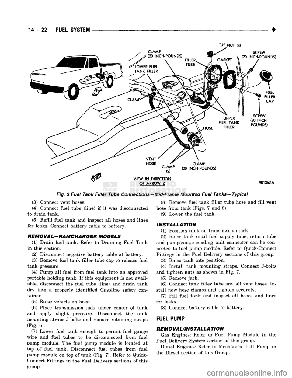
Fig. 3 Fuel Tank Filler Tube
Connections-
(3) Connect vent hoses.
(4) Connect fuel tube (line) if it was disconnected
to drain tank. (5) Refill fuel tank and inspect all hoses and lines
for leaks. Connect battery cable to battery.
RE MO VA L—RAMCHARGER MODELS (1) Drain fuel tank. Refer to Draining Fuel Tank
in this section. (2) Disconnect negative battery cable at battery.
(3) Remove fuel tank filler tube cap to release fuel
tank pressure. (4) Pump all fuel from fuel tank into an approved
portable holding tank. If this equipment is not avail
able,
disconnect the fuel tube (line) and drain tank
dry into a properly identified Gasoline safety con
tainer.
(5) Raise vehicle on hoist.
(6) Place transmission jack under center of tank
and apply slight pressure. Disconnect the tank
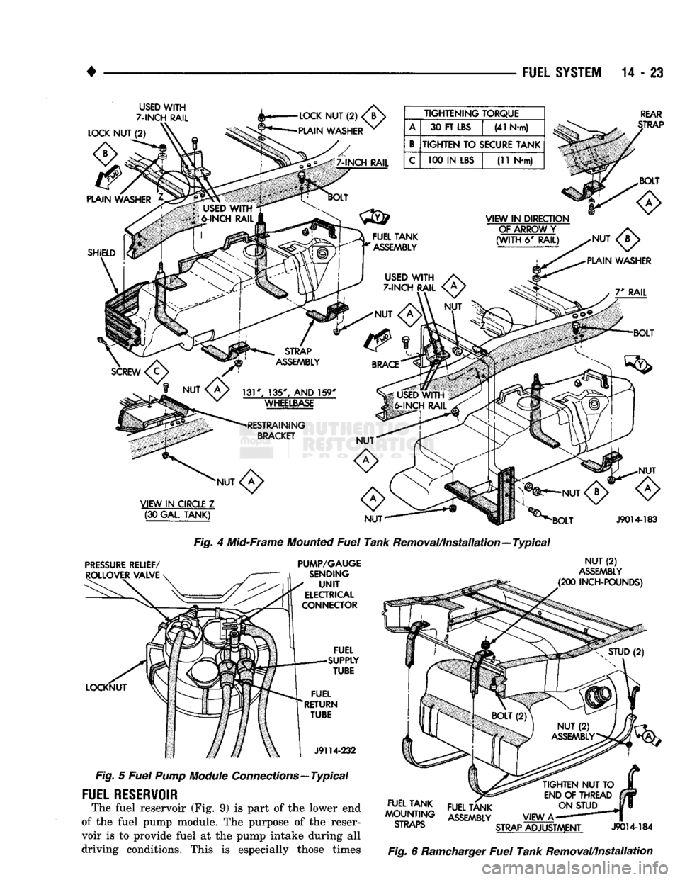
mounting straps J-bolts and remove retaining straps (Fig. 6).
(7) Lower fuel tank enough to permit fuel gauge
wire and fuel tubes to be disconnected from fuel
pump module. The fuel pump module is located at
top of fuel tank. Disconnect fuel tubes from fuel
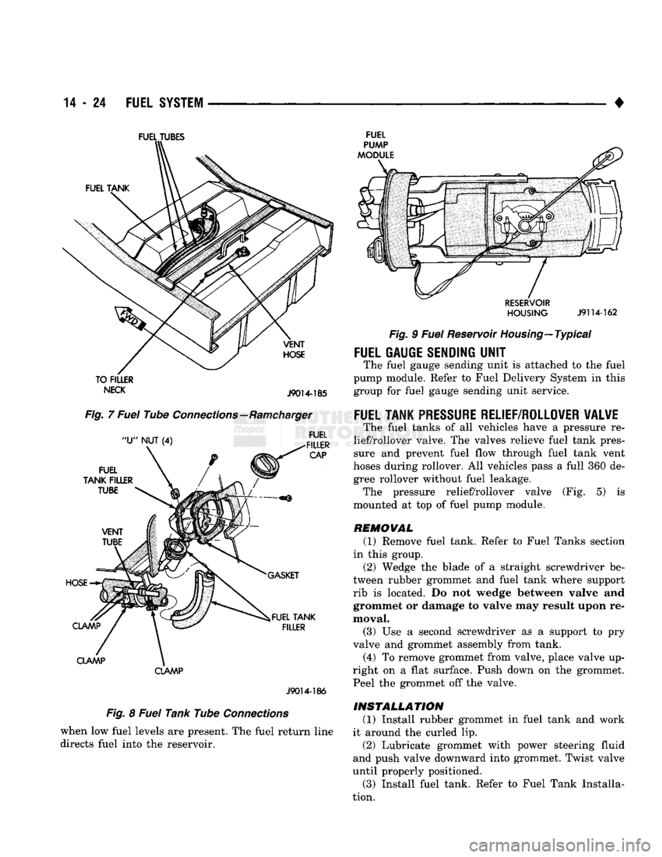
pump module on top of tank (Fig. 7). Refer to Quick- Connect Fittings in the Fuel Delivery sections of this
group. -Mid-Frame
Mounted
Fuel
Tanks—Typical
(8) Remove fuel tank filler tube hose and fill vent
hose from tank (Figs. 7 and 8). (9) Lower the fuel tank.
INSTALLATION (1) Position tank on transmission jack.
(2) Raise tank until fuel supply tube, return tube
and pump/gauge sending unit connector can be con
nected to fuel pump module. Refer to Quick-Connect Fittings in the Fuel Delivery sections of this group.
(3) Raise tank into position. (4) Install tank mounting straps. Connect J-bolts
and tighten nuts as shown in Fig. 7.
(5) Remove jack. (6) Connect tank filler tube and all vent hoses. In
stall new hose clamps and tighten securely. (7) Fill fuel tank and inspect all hoses and lines
for leaks. (8) Connect battery cable to battery.
FUEL PUMP
REMOVAL/INSTALLA TION Gas Engines: Refer to Fuel Pump Module in the
Fuel Delivery System section of this group. Diesel Engines: Refer to Mechanical Lift Pump in
the Diesel section of this Group.
Page 842 of 1502
•
FUEL SYSTEM
14 - 23
USED
WITH
7-INCH
RAIL TIGHTENING TORQUE
A
30 FT
LBS
(41 N-m)
B
TIGHTEN
TO
SECURE TANK
C
100 IN
LBS
(11 N-m)
REAR
STRAP
VIEW
IN
CIRCLE
Z (30 GAL
TANK)
PRESSURE
RELIEF/
ROLLOVER
VALVE
LOCKNUT Fig.
4 Mid-Frame Mounted
Fuel
Tank Removal/Installation—Typical
PUMP/GAUGE
SENDING
UNIT
ELECTRICAL
CONNECTOR FUEL
SUPPLY
TUBE
FUEL
RETURN TUBE
J9114-232
J9014-183
NUT
(2)
ASSEMBLY
(200
INCH-POUNDS)
Fig.
5
Fuel Pump
Module Connections—Typical
FUEL
RESERVOIR
The fuel reservoir (Fig. 9) is part of the lower end
of the fuel pump module. The purpose of the reser
voir is to provide fuel at the pump intake during all
driving conditions. This is especially those times
TIGHTEN
NUT TO
END
OF
THREAD ON STUD
VIEW
A-
STRAP
ADJUSTMENT
J9014-184
Fig.
6 Ramcharger
Fuel
Tank Removal/Installation
FUEL TANK
^OUNTWG ASSEMBLY
ol
KAP5>
Page 843 of 1502
14
- 24
FUEL
SYSTEM
•
FUEL
TUBES
TO FILLER
NECK
J9014-185
Fig. 7 Fuel Tube Connections—Ramcharger
CLAMP
J9014-186
Fig. 8 Fuel Tank Tube Connections when low fuel levels are present. The fuel return line
directs fuel into the reservoir.
FUEL
HOUSING
J9114-162
Fig. 9 Fuel Reservoir Housing—Typical
FUEL
GAUGE SENDING
UNIT
The fuel gauge sending unit is attached to the fuel
pump module. Refer to Fuel Delivery System in this
group for fuel gauge sending unit service.
FUEL TANK
PRESSURE
RELIEF/ROLLOVER VALVE
The fuel tanks of all vehicles have a pressure re
lief/rollover valve. The valves relieve fuel tank pres
sure and prevent fuel flow through fuel tank vent
hoses during rollover. All vehicles pass a full 360 de gree rollover without fuel leakage. The pressure relief/rollover valve (Fig. 5) is
mounted at top of fuel pump module.
REMOVAL (1) Remove fuel tank. Refer to Fuel Tanks section
in this group. (2) Wedge the blade of a straight screwdriver be
tween rubber grommet and fuel tank where support
rib is located. Do not wedge between valve and grommet or damage to valve may result upon re
moval.
(3) Use a second screwdriver as a support to pry
valve and grommet assembly from tank. (4) To remove grommet from valve, place valve up
right on a flat surface. Push down on the grommet. Peel the grommet off the valve.
INSTALLATION
(1) Install rubber grommet in fuel tank and work
it around the curled lip. (2) Lubricate grommet with power steering fluid
and push valve downward into grommet. Twist valve
until properly positioned.
(3) Install fuel tank. Refer to Fuel Tank Installa
tion.
Page 844 of 1502
FUEL
SYSTEM 14-25
ACCELERATOR PEDAL AND THROTTLE CABLE
INDEX
page
Accelerator Pedal
........................
25
General
Information
25
GENERAL
INFORMATION
All
gas
powered models have torsion return springs
on
the
throttle body. Models equipped with
a
manual
transmission have
an
additional pedal return spring (Fig.
1).
These springs give positive throttle return
and lower throttle pedal efforts while meeting safety
requirements.
Fig.
1
Throttle
Body
Return
Spring—Manual
Transmission—Except
Diesel
ACCELERATOR
PEDAL
CAUTION:
Be
careful
not
to
damage
or
kink
the
ca
ble core
wire
(within
the
cable sheathing) while ser
vicing
accelerator
pedal
or
cables.
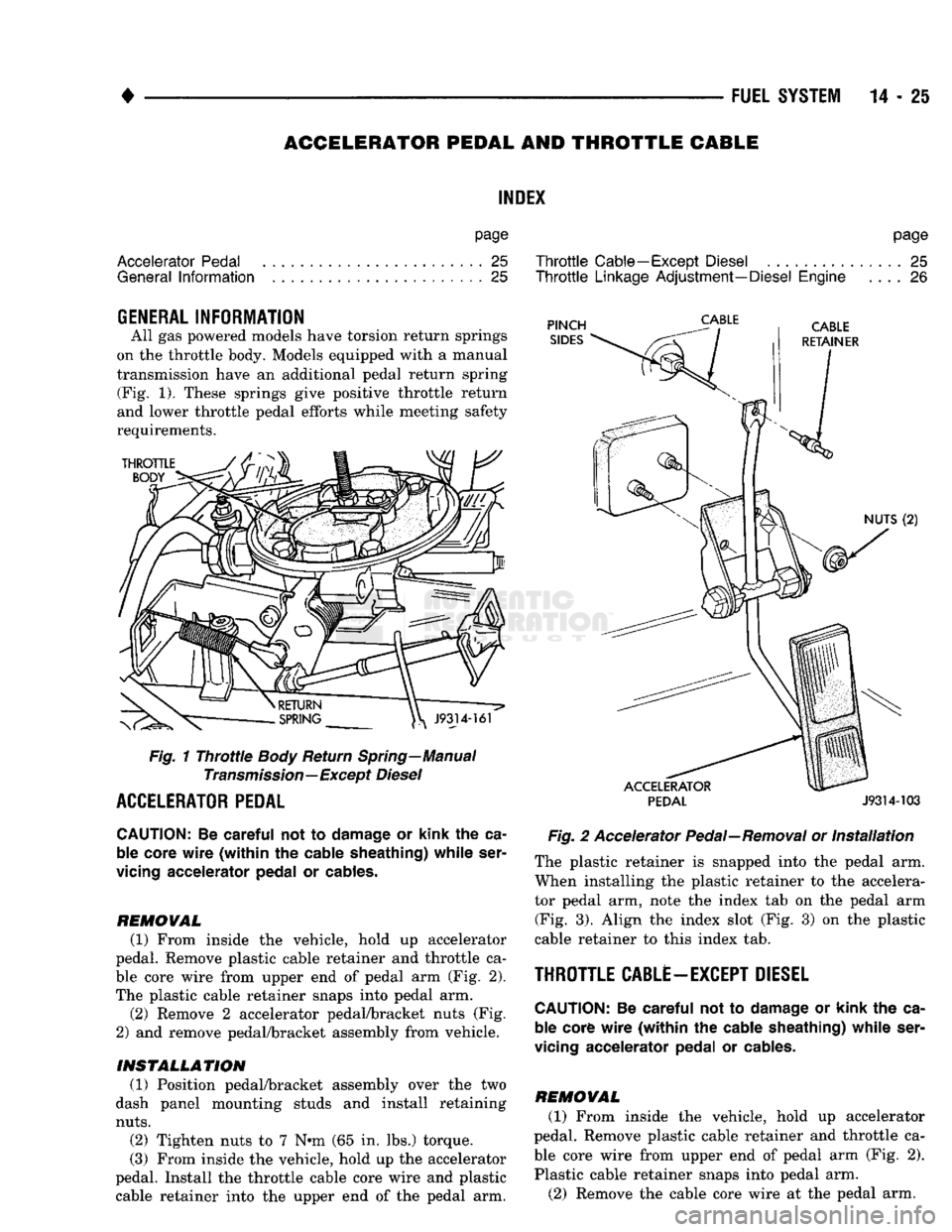
REMOVAL (1)
From inside
the
vehicle, hold
up
accelerator
pedal. Remove plastic cable retainer
and
throttle
ca
ble core wire from upper
end of
pedal
arm (Fig. 2).
The plastic cable retainer snaps into pedal
arm.
(2)
Remove
2
accelerator pedal/bracket nuts
(Fig.
2)
and
remove pedal/bracket assembly from vehicle.
INSTALLATION (1)
Position pedal/bracket assembly over
the two
dash panel mounting studs
and
install retaining
nuts.
(2)
Tighten nuts
to 7 N*m
(65
in. lbs.)
torque.
(3) From inside
the
vehicle, hold
up the
accelerator
pedal. Install
the
throttle cable core wire
and
plastic cable retainer into
the
upper
end of the
pedal
arm.
page
Throttle
Cable—Except Diesel
...............
25
Throttle
Linkage Adjustment—Diesel Engine
.... 26
PINCH
SIDES
PEDAL
J9314-103
Fig.
2
Accelerator Pedal—Removal
or
Installation
The plastic retainer
is
snapped into
the
pedal
arm.
When installing
the
plastic retainer
to the
accelera
tor pedal
arm,
note
the
index
tab on the
pedal
arm
(Fig.
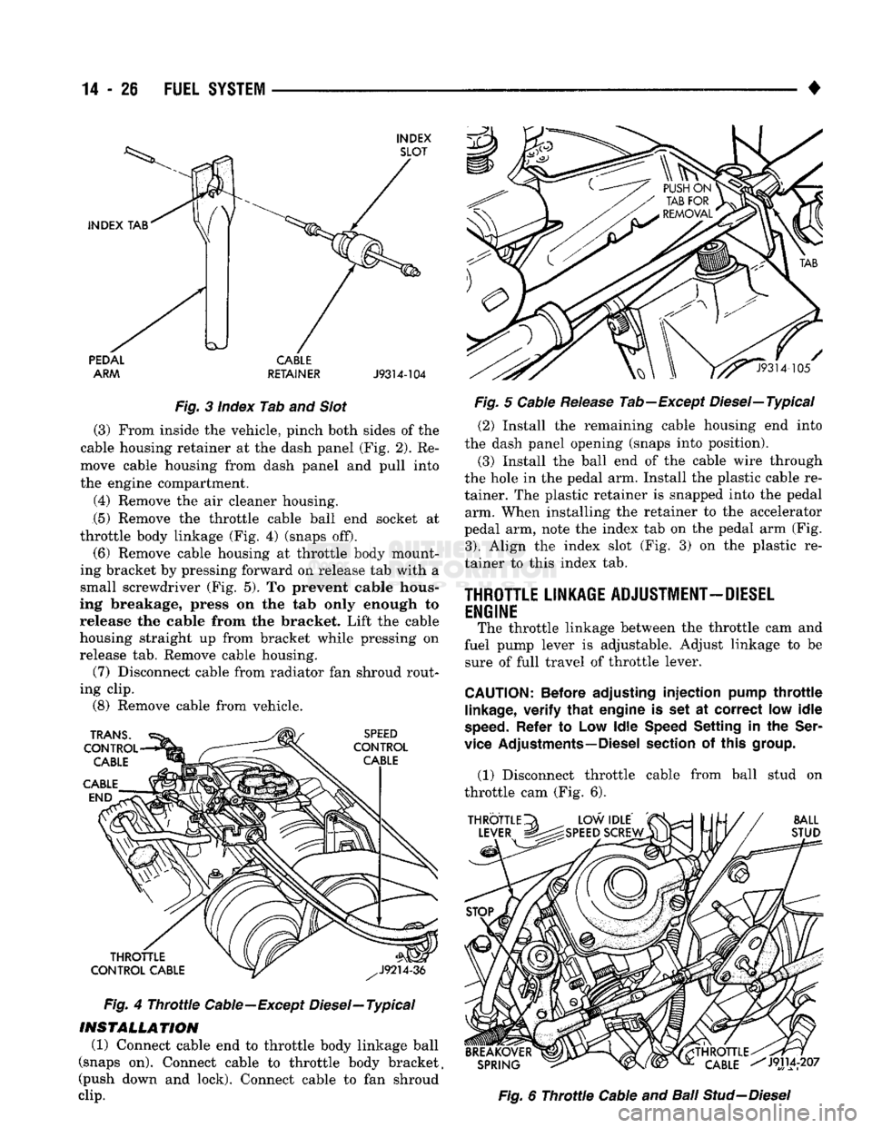
3).
Align
the
index slot
(Fig. 3) on the
plastic
cable retainer
to
this index
tab.
THROTTLE CABLE-EXCEPT DIESEL
CAUTION:
Be
careful
not
to
damage
or
kink
the
ca
ble core
wire
(within
the
cable sheathing) while ser
vicing
accelerator
pedal
or
cables.
REMOVAL (1)
From inside
the
vehicle, hold
up
accelerator
pedal. Remove plastic cable retainer
and
throttle
ca
ble core wire from upper
end of
pedal
arm (Fig. 2).
Plastic cable retainer snaps into pedal
arm.
(2)
Remove
the
cable core wire
at the
pedal
arm.
Page 845 of 1502
14
- 26
FUEL
SYSTEM
•
INDEX SLOT
INDEX
TAB PEDAL
ARM CABLE
RETAINER
J9314-104
Fig.
3 Index Tab and
Slot
(3) From inside the vehicle, pinch both sides of the
cable housing retainer at the dash panel (Fig. 2). Re
move cable housing from dash panel and pull into
the engine compartment.
(4) Remove the air cleaner housing. (5) Remove the throttle cable ball end socket at
throttle body linkage (Fig. 4) (snaps off).
(6) Remove cable housing at throttle body mount
ing bracket by pressing forward on release tab with a
small screwdriver (Fig. 5). To prevent cable hous
ing breakage, press on the tab only enough to release the cable from the bracket. Lift the cable
housing straight up from bracket while pressing on
release tab. Remove cable housing. (7) Disconnect cable from radiator fan shroud rout
ing clip. (8) Remove cable from vehicle.
TRANS.
CONTROL CABLE
CABLE END SPEED
CONTROL CABLE
THROTTLE
CONTROL CABLE
Fig.
4
Throttle
Cable—Except Diesel—Typical
INSTALLATION
(1) Connect cable end to throttle body linkage ball
(snaps on). Connect cable to throttle body bracket,
(push down and lock). Connect cable to fan shroud
clip.
^^J9314-105
Fig.
5 Cable
Release
Tab—Except Diesel—Typical (2) Install the remaining cable housing end into
the dash panel opening (snaps into position).
(3) Install the ball end of the cable wire through
the hole in the pedal arm. Install the plastic cable re
tainer. The plastic retainer is snapped into the pedal arm. When installing the retainer to the accelerator
pedal arm, note the index tab on the pedal arm (Fig.
3).
Align the index slot (Fig. 3) on the plastic re
tainer to this index tab.
THROTTLE LINKAGE ADJUSTMENT-DIESEL
ENGINE The throttle linkage between the throttle cam and
fuel pump lever is adjustable. Adjust linkage to be sure of full travel of throttle lever.
CAUTION:
Before adjusting
injection
pump
throttle
linkage,
verify
that
engine
is set at
correct
low
idle
speed.
Refer
to Low
Idle
Speed Setting
in the
Ser
vice Adjustments—Diesel section
of
this group.
(1) Disconnect throttle cable from ball stud on
throttle cam (Fig. 6).
THROTTLE
LEVER BALL
STUD
BREAKOVER SPRING
THROTTLE.
CABLE
^J9114r207
Fig.
6
Throttle
Cable and Bali
Stud-Diesel
Page 846 of 1502
•
FUEL
SYSTEM
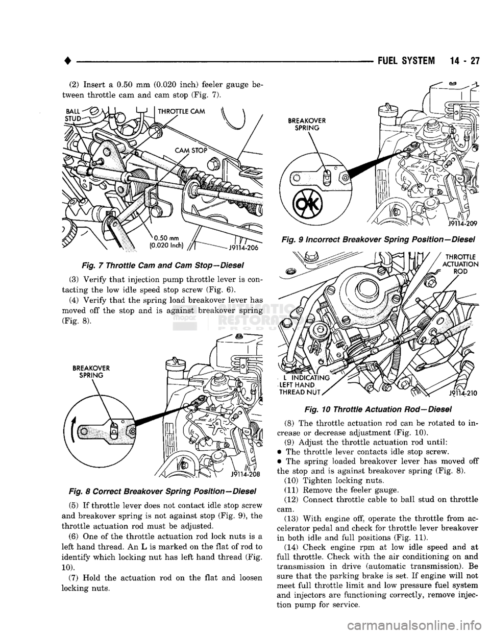
14 - 27 (2) Insert a 0.50 mm (0.020 inch) feeler gauge be
tween throttle cam and cam stop (Fig. 7). BALL
STUD
J9114-206
Fig.
7
Throttle
Cam and Cam
Stop—Diesel
(3) Verify that injection pump throttle lever is con
tacting the low idle speed stop screw (Fig. 6). (4) Verify that the spring load breakover lever has
moved off the stop and is against breakover spring (Fig. 8).
BREAKOVER SPRING
J9114-208
Fig.
8 Correct Breakover
Spring
Position—Diesel
(5) If throttle lever does not contact idle stop screw
and breakover spring is not against stop (Fig. 9), the
throttle actuation rod must be adjusted.
(6) One of the throttle actuation rod lock nuts is a
left hand thread. An L is marked on the flat of rod to
identify which locking nut has left hand thread (Fig.
10).
(7) Hold the actuation rod on the flat and loosen
locking nuts. '
BREAKOVER
SPRING
J9114-209
Fig.
9 Incorrect Breakover
Spring
Position—Diesel
THROTTLE
ACTUATION
ROD
L
INDICATING
LEFT
HAND
THREAD
NUT
J9114-210
Fig.
10
Throttle
Actuation
Rod—Diesel
(8) The throttle actuation rod can be rotated to in
crease or decrease adjustment (Fig. 10). (9) Adjust the throttle actuation rod until:
• The throttle lever contacts idle stop screw.
• The spring loaded breakover lever has moved off
the stop and is against breakover spring (Fig. 8).
(10) Tighten locking nuts. (11) Remove the feeler gauge.
(12) Connect throttle cable to ball stud on throttle
cam.
(13) With engine off, operate the throttle from ac
celerator pedal and check for throttle lever breakover
in both idle and full positions (Fig. 11).
(14) Check engine rpm at low idle speed and at
full throttle. Check with the air conditioning on and
transmission in drive (automatic transmission). Be sure that the parking brake is set. If engine will not
meet full throttle limit and low pressure fuel system and injectors are functioning correctly, remove injec
tion pump for service.
Page 847 of 1502
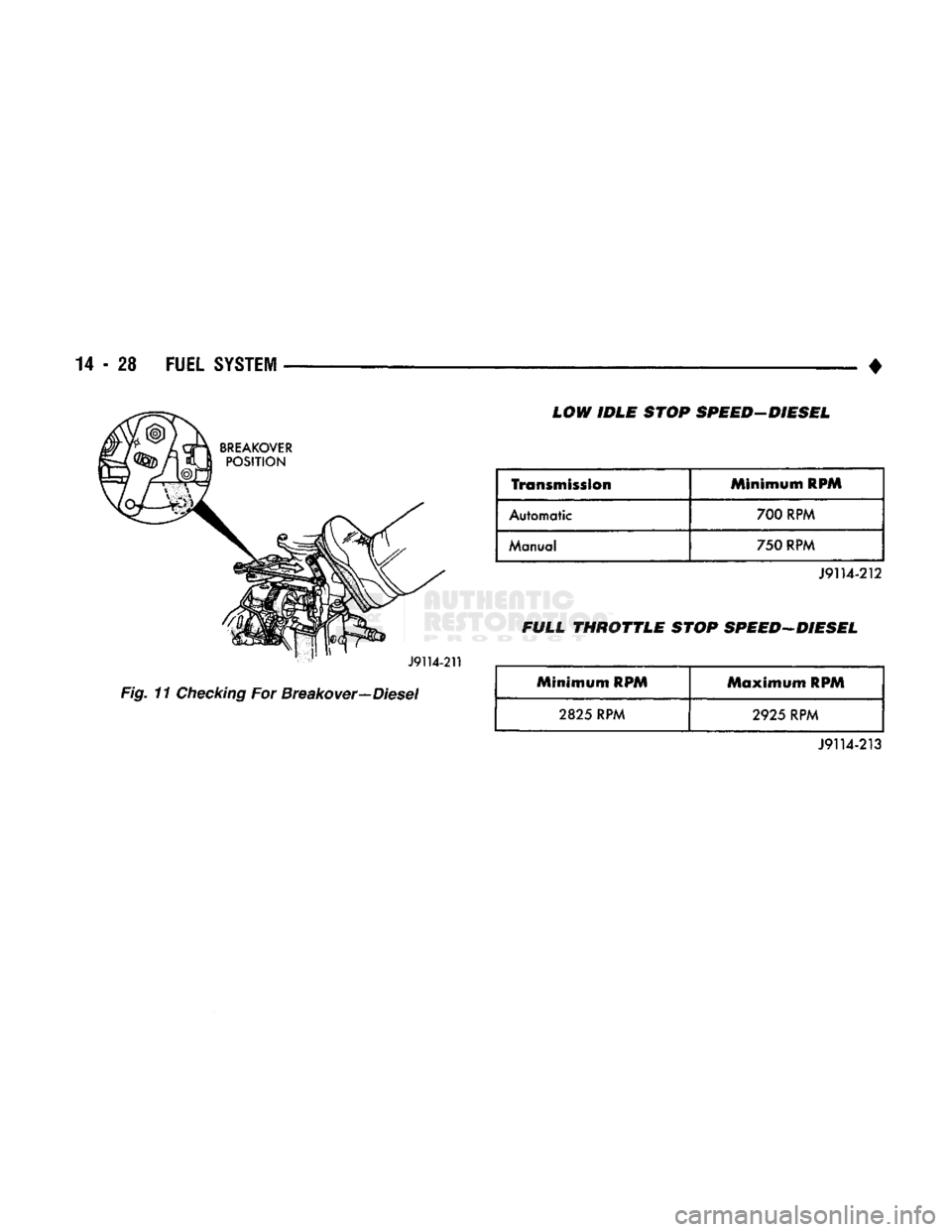
Fig.
11
Checking
For Breakover—Diesel LOW IDLE STOP SPEED-DIESEL
Transmission
Minimum
RPM
Automatic 700 RPM
Manual 750 RPM
J9114-212
FULL
THROTTLE
STOP SPEED-DIESEL
Minimum RPM
Maximum
RPM
2825 RPM 2925 RPM
J9114-213
Page 848 of 1502
•
FUEL
SYSTEM
14-29
MULTI-PORT
FUEL
INJECTION
(MPI)-COMPONENT DESCRIPTION/SYSTEM
OPERATION-EXCEPT DIESEL
INDEX
page
Air
Conditioning (A/C) Clutch
Relay-Pern
Output
. 35
Air
Conditioning (A/C)
Controls—PCM
Input
.... 31
Auto
Shut
Down
(ASD)
Relay-PCM
Output
. ... 36
Automatic
Shut
Down
(ASD)
Sense-PCM
Input
. 31
Battery
Voltage-PCM
Input
32
Brake
Switch-PCM
Input
32
Camshaft
Position
Sensor—PCM
Input
32
Charge
Air
Temperature
Sensor—PCM
Input
. . . 32
Crankshaft
Position
Sensor-PCM
Input
.......
32
Electric
Exhaust
Gas Recirculation Transducer
(EET)
Solenoid-PCM
Output
...
.......
36
Engine
Coolant Temperature
Sensor—PCM
Input
. 33
EVAP
Canister
Purge
Solenoid—PCM
Output
. . . 37
Fuel
Injectors-PCM Output
37
Fuel
Pressure
Regulator
41
Fuel
Rail
41
General
Information
.......................
29
Generator
Field-PCM
Output
36
Generator
Lamp-PCM
Output
36
Idle
Air
Control
(IAC)
Motor-PCM
Output
......
36
Ignition
Circuit
Sense—PCM
Input
33
GENERAL
INFORMATION
All
gas
powered engines
are
equipped with sequen
tial Multi-Port Fuel Injection (MPI).
The MPI
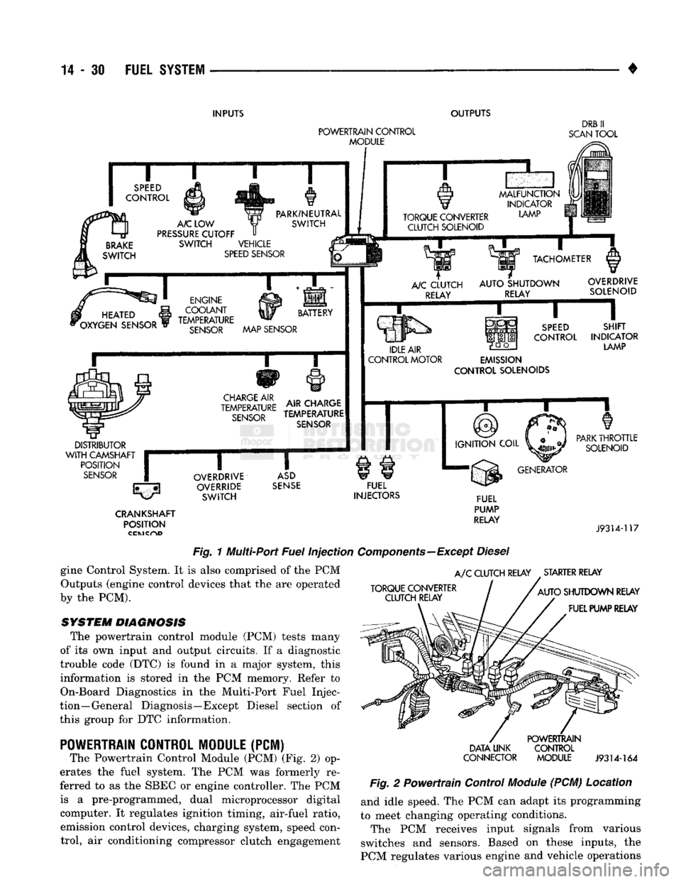
system (Fig.
1)
provides precise air/fuel ratios
for all
driving
conditions. The Powertrain Control Module
(PCM)
operates
the fuel system.
The PCM was
formerly referred
to
as
the
SBEC
or
engine controller.
The PCM is a
pre
programmed, dual microprocessor digital computer. It regulates ignition timing, air-fuel ratio, emission
control devices, charging system, speed control,
air
conditioning compressor clutch engagement
and
idle speed.
The PCM can
adapt
its
programming
to
meet
changing operating conditions.
Powertrain Control Module (PCM) Inputs rep
resent
the
instantaneous engine operating conditions.
Air-fuel mixture
and
ignition timing calibrations
for
various driving
and
atmospheric conditions
are
pre
programmed into
the PCM. The PCM
monitors
and
analyzes various inputs.
It
then computes engine fuel
and ignition timing requirements based
on
these
in
puts.
Fuel delivery control
and
ignition timing will
then
be
adjusted accordingly. Other inputs
to the
PCM
are
provided
by the
brake
light switch,
air
conditioning select switch
and the
speed control switches.
All
inputs
to the PCM are
converted into signals. Electrically operated fuel injectors spray fuel
in
precise metered amounts into
the
intake port directly above
the
intake valve.
The
injectors
are
fired
in a
specific sequence
by the PCM. The PCM
maintains
page
Ignition
Coil-PCM
Output
37
Malfunction Indicator
Lamp—PCM
Output
37
Manifold
Absolute
Pressure
(MAP)
Sensor-
PCM
Input
33
Open
Loop/Closed
Loop
Modes
of
Operation
. . . 38
Overdrive/Override
Switch
34
Oxygen
(02)
Sensor—PCM
Input
33
Park/Neutral
Switch—PCM
Input
34
Power
Ground
34
Powertrain Control Module
(PCM)
30
SCI
Receive-PCM
Input
. 34
SCI
Transmit-PCM
Output
37
Sensor
Return
—PCM
Input
35
Shift Indicator-PCM Output
38
Speed
Control-PCM
Input
34
Speed
Control-PCM
Output
38
SRI
Lamp-PCM
Output
36
Tachometer—PCM
Output
38
Throttle
Body
40
Throttle
Position
Sensor
(TPS)-PCM
Input
35
Vehicle
Speed
Sensor-PCM
Input
35
an air/fuel ratio
of 14.7 to 1 by
constantly adjusting
injector pulse width. Injector pulse width
is the
length
of
time that
the
injector opens
and
sprays fuel into
the
chamber.
The PCM
adjusts injector pulse
width
by
opening
and
closing
the
ground path
to the
injector.
Manifold absolute pressure
(air
density)
and
engine
rpm (speed)
are the
primary inputs that determine
fuel injector pulse width.
The PCM
also monitors
other inputs when adjusting air-fuel ratio.
Inputs That Effect Fuel Injector Pulse Width:
• Exhaust
gas
oxygen content
• Coolant temperature
• Manifold absolute pressure (MAP)
• Engine speed
• Throttle position
• Battery voltage •
Air
conditioning selection
• Transmission gear selection (auto, trans.)
• Speed control The powertrain control module (PCM) adjusts igni
tion timing
by
controlling ignition coil operation.
The
ignition coil receives battery voltage when
the
igni
tion
key is in the run or
starter (crank) position.
The
PCM provides
a
ground
for the
ignition coil.
The
coil
discharges when
the PCM
supplies
a
ground.
By
switching
the
ground path
on and off, the PCM
reg
ulates ignition timing.
The sensors
and
switches that provide inputs
to the
powertrain control module
(PCM)
comprise
the En-
Page 849 of 1502
14
- 30
FUEL
SYSTEM
INPUTS
OUTPUTS
POWERTRAIN
CONTROL
MODULE
DRB
II
SCAN
TOOL
SPEED
CONTROL
BRAKE
SWITCH
A/C
LOW
PRESSURE
CUTOFF
SWITCH VEHICLE
SPEED
SENSOR PARK/NEUTRAL
SWITCH TORQUE CONVERTER
CLUTCH SOLENOID
MALFUNCTION
INDICATOR
LAMP
m
HEATED
i
*OXYGEN SENSOR ENGINE
COOLANT
yy
BATTERY
TEMPERATURE
SENSOR
MAP SENSOR
i—r
CHARGE
AIR
TEMPERATURE
SENSOR
AIR CHARGE
TEMPERATURE
SENSOR
DISTRIBUTOR
WITH
CAMSHAFT
r
POSITION
SENSOR
(|
TACHOMETER
A/C
CLUTCH RELAY
AUTO
SHUTDOWN
RELAY OVERDRIVE
SOLENOID
IDLE AIR
CONTROL MOTOR
SPEED
CONTROL
SHIFT
INDICATOR
LAMP
EMISSION
CONTROL SOLENOIDS
IGNITION
COIL
OVERDRIVE
OVERRIDE SWITCH
ASD
SENSE
FUEL
INJECTORS
PARK
THROTTLE
SOLENOID
GENERATOR CRANKSHAFT
POSITION FUEL
PUMP
RELAY
J9314-117
Fig.
1 Multi-Port
Fuel
Injection
Components—Except
Diesel
gine Control System. It is also comprised of the PCM Outputs (engine control devices that the are operated
by the PCM).
SYSTEM DIAGNOSIS
The powertrain control module (PCM) tests many
of its own input and output circuits. If a diagnostic
trouble code (DTC) is found in a major system, this information is stored in the PCM memory. Refer to
On-Board Diagnostics in the Multi-Port Fuel Injec
tion—General Diagnosis—Except Diesel section of
this group for DTC information.
POWERTRAIN
CONTROL MODULE (PCM)
The Powertrain Control Module (PCM) (Fig. 2) op
erates the fuel system. The PCM was formerly re
ferred to as the SBEC or engine controller. The PCM is a pre-programmed, dual microprocessor digital computer. It regulates ignition timing, air-fuel ratio, emission control devices, charging system, speed control, air conditioning compressor clutch engagement
A/C
CLUTCH RELAY STARTER RELAY
TORQUE CONVERTER CLUTCH RELAY
AUTO
SHUTDOWN RELAY
FUEL PUMP RELAY
DATA UNK
CONNECTOR
POWERTRAIN
CONTROL MODULE
J9314-164
Fig.
2 Powertrain Control
Module
(PCM) Location and idle speed. The PCM can adapt its programming
to meet changing operating conditions.
The PCM receives input signals from various
switches and sensors. Based on these inputs, the
PCM regulates various engine and vehicle operations
Page 850 of 1502
•
FUEL SYSTEM
14-31 through different system components. These compo
nents are referred to as Powertrain Control Module
(PCM) Outputs. The sensors and switches that pro
vide inputs to the PCM are considered Powertrain Control Module (PCM) Inputs.
The PCM adjusts ignition timing based upon in
puts it receives from sensors that react to: engine rpm, manifold absolute pressure, engine coolant tem
perature, throttle position, transmission gear selec
tion (automatic transmission), vehicle speed and the
brake switch.
The PCM adjusts idle speed based on inputs it re
ceives from sensors that react to: throttle position,
vehicle speed, transmission gear selection, engine coolant temperature and from inputs it receives from
the air conditioning clutch switch and brake switch.
Based on inputs that it receives, the PCM adjusts
ignition coil dwell. The PCM also adjusts the gener
ator charge rate through control of the generator
field and provides speed control operation.
Powertrain Control Module (PCM) Inputs:
• Generator output • A/C request (if equipped with factory A/C)
• A/C select (if equipped with factory A/C)
• Auto shut down (ASD) sense
• Charge air temperature sensor
• Battery voltage
• Brake switch
• Engine coolant temperature sensor
• Crankshaft position sensor • Ignition circuit sense (ignition switch in run posi
tion)
• Manifold absolute pressure (MAP) sensor
• Overdrive/override switch
• Oxygen sensor(s)
• Park/neutral switch (auto, trans, only)
• SCI receive (DRB II connection) • Speed control resume switch
• Speed control set switch • Speed control on/off switch
• Camshaft position sensor signal
• Throttle position sensor
• Vehicle speed sensor
• Sensor return
• Power ground
• Signal ground Powertrain Control Module (PCM) Outputs:
• A/C clutch relay
• Idle air control (IAC) motor
• Auto shut down (ASD) relay
• Generator field
• Malfunction indicator lamp
• Service reminder indicator lamp
• EGR valve control solenoid • Fuel injectors
• Fuel pump relay
• Ignition coil • EVAP canister purge solenoid
• SCI transmit (DRB II connection)
• Shift indicator lamp (manual transmission only)
• Speed control vacuum solenoid
• Speed control vent solenoid
• Tachometer (on instrument panel, if equipped) The powertrain control module (PCM) contains a
voltage convertor. This converts battery voltage to a
regulated 8.0 volts. It is used to power the crankshaft
position sensor and camshaft position sensor. The
PCM also provides a five (5) volt supply for the man ifold absolute pressure (MAP) sensor and throttle po
sition sensor (TPS).
AIR
CONDITIONING
(A/C)
CONTROLS-PCM
INPUT
The A/C control system information applies to fac
tory installed air conditioning units. A/C SELECT SIGNAL: When the A/C switch is
in the ON position and the A/C low pressure switch
is closed, an input signal is sent to the powertrain
control module (PCM). The signal informs the PCM
that the A/C has been selected. The PCM adjusts idle speed to a pre-programmed rpm through the idle air
control (IAC) motor to compensate for increased en
gine load. A/C REQUEST SIGNAL: Once A/C has been se
lected, the powertrain control module (PCM) receives
the A/C request signal from the evaporator switch.
The input indicates that the evaporator temperature is in the proper range for A/C application. The PCM
uses this input to cycle the A/C compressor clutch (through the A/C relay). It will also determine the
correct engine idle speed through the idle air control (IAC) motor position. If the A/C low pressure switch opens (indicating a
low refrigerant level), the PCM will not receive an
A/C select signal. The PCM will then remove the ground from the A/C relay. This will deactivate the
A/C compressor clutch. If the evaporator switch opens, (indicating that
evaporator is not in proper temperature range), the
PCM will not receive the A/C request signal. The
PCM will then remove the ground from the A/C re lay, deactivating the A/C compressor clutch.
AUTOMATIC SHUT DOWN
(ASD)
SENSE-PCM INPUT
A 12 volt signal at this input indicates to the PCM
that the ASD has been activated. The ASD relay is located in the engine compartment (Fig. 2). It is used
to connect the oxygen sensor(s) heater element, igni
tion coil, generator field winding and fuel injectors to 12 volt + power supply. This input is used only to sense that the ASD relay
is energized. If the powertrain control module (PCM)
does not see 12 volts at this input when the ASD
should be activated, it will set a diagnostic trouble
code (DTC).